IEEE Transactions on Consumer Electronics, Vol. 50, No. 2, MAY 2004
498
Java-Based Home Automation System A. R. Al-Ali, Member, IEEE & M. AL-Rousan Abstract — This paper presents the design and implementation of a Java-based automation system that can monitor and control home appliances via the World Wide Web. The design is based on a stand alone embedded system board integrated into a PC-based server at home. The home appliances are connected to the input/output ports of the embedded system board and their status are passed to the server. The monitoring and control software engine is based on the combination of JavaServer Pages, JavaBeans, and Interactive C. The home appliances can be monitored and controlled locally via the embedded system board, or remotely through a web browser from anywhere in the world provided that an Internet access is available. The system is scalable and allows multi-vendor appliances to be added with no major changes to its core. Password protection is used to block unauthorized users from accessing the appliances at home. If the Internet connection is down or the server is not up, the embedded system board still can control and operate the appliances locally Index Terms — Embedded System, Home Automation, Internet-based, JavaServer Pages. I.
INTRODUCTION
Due to the rapid development in computer and network technology, the use of the Internet has been expanding exponentially. It is now extensively used as a reference tool for personal, educational, commercial, and industrial use. For many years the Internet has been used extensively in browsing homepages, searching for information, chatting, downloading and uploading information. Due to the rapid development of new technologies such as JAVA, the Internet has also started to serve as a medium that allows the monitoring, control, and interaction with machine and devices. The Internet can be used in home automation which provides many features ranging from efficient use of energy to increased comfort, greater safety and security. Even over large distances the user can monitor and control his/her home gate, oven, refrigerator and water the garden without any human intervention. Despite these attractions and benefits, home automation has not yet received broad acceptance and attention. This is mainly due to its high cost and complexity as well as the lack of security.
A. R. Al-Ali is with the Computer Engineering Department, School of Engineering, American University of Sharjah, Sharjah, P.O. Box 26666, UAE (e-mail: aali@ ausharjah.edu). M. AL-Rousan is with the Computer Engineering Department, School of Engineering, American University of Sharjah, Sharjah, P.O. Box 26666, UAE. He is on leave from Jordan University of Science & Technology, Irbid, Jordan. (e-mail:
[email protected]). Contributed Paper Manuscript received February 29, 2004
Neng presented an architecture for home automation [1]. The work showed how home appliances could be controlled by an integrated system. However, the proposed system is based on a dedicated network and has never been tested on the Internet. Moreover, the system only shows how to solve home automation problems at the software level; hardware aspects were not considered. Nunes and Delgado [2] proposed an Internet application that allows local and remote monitoring and control of a home. The application adopted an objectoriented approach to represent each home component as an object that is connected to a server at home. The research was carried out using a model for the application but no real experiments were done. The paper does not discuss the hardware implementation and assumes that home appliances have built-in controllers and are ready for Internet access. The power and usefulness of Java in Internet applications have been under thorough testing by several researchers. The design and implantation of a portable, light-weight userinterface for a home automation system is proposed in [3-4]. The emphasis was on the use of Java in developing software user interfaces to provide remote access to the home control system. They described the software aspects in designing user interfaces using Handheld Device Markup Language (HDML) and Remote Frame Buffer (RFB) protocols. Their work did not focus on hardware aspects. Sriskanthan proposed an automation system that can control home appliances from a PC using Bluetooth [5]. However, the system cannot be controlled remotely through the Internet. Another approach to home automation using Bluetooth was discussed by Shepered [6] but no implementations were proposed. Wong introduced a phone-based system for home and office automation using a hardware-based remote controller for home appliances [7]. Communication takes place via a dedicated telephone line not via the Internet. A similar system has been designed for remote home automation using the telephone by Coskun and Ardam [8]. The studies presented in [9-13] have enriched the field of Web-based real time applications. The presented systems are able to control, monitor, and interact with real devices used in university laboratories. Real experiments have been conducted through the Internet. Although these systems can be easily migrated towards home automation, the use of ready made software packages and proprietary hardware tools make the system more expensive. Also, Java applets, HTML, JavaScript and Visual Basic script have been used in implementation. This makes the system complex and not less flexible. Other highlighted requirements and considerations of home automation systems are discussed in [14].
0098 3063/04/$20.00 © 2004 IEEE
A. R. Al-Ali and M. AL-Rousan: Java-Based Home Automation System
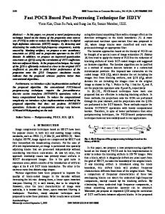
In this paper, we present an attractive low-cost solution for home automation via the Internet. Using Internet access, home owners can remotely monitor and control almost any appliance at home. Local control is also offered in our design. Some security is imposed when logging into the system using Java Beans and Java Server Pages (JSPs). Appliances at home are connected to an embedded system board (E-board). The control code on the E-board operates the appliances and communicates with Java-based code that resides at the server at home. The user can interact with the home automation system from anywhere at any time. Furthermore, the system is flexible and scalable. Additional home appliances can be integrated into the system with little modification. Since the server’s software engine is written in Java, it is portable and can run on any platform. Figure 1 shows the block diagram of the system’s architecture. This paper is organized as follows: In Section II, the system’s general architecture and hardware implementation are discussed. Section III describes the system’s software implementation. Discussion is presented in Section IV followed by conclusion in Section V.
Home Server
Remote Client
Internet
Remote Client
E-Board
Home Appliances
Figure 1: System hardware layout.
II. HARDWARE ARCHITECTURE & IMPLEMENTATION The core of the home automation system consists of two hardware components: the home server and the E-board. The home server is a high-end PC that hosts the Java-based management and control algorithm that enables the user to access the home appliances through the Internet. It also communicates with the E-board via the parallel port to download and upload the control commands and appliance’s status. The E-board is connected to the home server via the parallel port. Using the E-board to control the appliances
499
gives the user the ability to control the home locally even if the internet service is not available or even if the PC is not ON. An off-the-shelf ready-made E-board based-on 8-bit microcontroller [15-16] is used. The E-board has digital input and output ports, memory, an expansion slot, a two-line 16digit LCD and extra hardware resources which make it suitable for the required task. The E-board can be programmed using the microcontroller’s native assembly language or the highlevel interactive-C language [15]. The latter was chosen to develop the platform for monitoring and control of the appliances locally. Home appliances are connected to the digital output of the E-board via relays to provide sufficiently high currents and voltage compatibility. Figure 2 shows the relay configuration for each device and figure 3 depicts the E-board’s communication with the home appliances. A dual multiplexer, MUX, is used to enable the user to switch between local and remote mode using the multiplexer selection line. If the selection line is high, the local mode is enabled and the Eboard processes the user’s request based on the input commands from MUX’s local inputs and the server is no longer communicating with the E-board. Otherwise, the remote mode is active and the commands are received by the E-board from the server’s parallel port. Sending a software command to turn a device ON/OFF may not grantee the successful operation of the device as the device may be defect. To overcome this problem, a feedback circuit has been designed and implemented to indicate the device’s actual status after it received the software command (ON/OFF). Once a command is sent to turn a device ON, the feedback circuit senses the current and gives an output signal indicating that the device is ON. Otherwise, the device is not functioning and a message will pop up informing the user that the command was not executed successfully. The main sensing element is a current transformer and signal conditioning circuit that will output a digital signal indicating if the device responded to the command correctly. When the remote mode is selected, the user can submit a command to control a certain home appliance remotely through the Internet. In such a case, the home server receives the client’s request and passes it to the E-board via the parallel port. Then, the E-board interactive-C code will take over the process. Since the parallel port has eight lines for data, up to 256 different commands can be coded and sent to the E-board ranging from the binary code 00000000 to 11111111. Coding commands this way will add the scalability feature to the home automation system. That is, more appliances can be added without changing the system design and connections. Furthermore, error detection mechanisms can be used to provide a more robust system. Even parity code format was used in the command format. For example, the even parity code 10101001 is a command to turn ON the light bulb in the living room. In case the command 10101000 was received due to transmission errors, the control software on the E-board will detect the error and report it back to the user. Table 1 shows samples of selected commands and associated actions.
IEEE Transactions on Consumer Electronics, Vol. 50, No. 2, MAY 2004
500
III. CONTROL AND MANAGEMENT (CAM) ENGINE This section describes the Control and Management (CAM) engine, which is the software driver that manages and controls the system operation. We have developed two separate engines; one running on the web (home) server and the other is running on the E-board as shown in Figure 4. The control engine resides on the board’s EPROM and is written in the Interactive C language [15]. It is referred to as C-Control and Management (CCAM) engine. The main function of this engine is to communicate with and control the circuits connected to the home appliances. The second engine, the control and management engine, resides on the home server and is based on Java components. It is referred to as Javabased Control and Management (JCAM) engine. Figure 2: Device relay interface
JCAM
Client Requests
CCAM
Home Appliances
Figure 4. Control and Management Engine
E-Board
Figure 3: Hardware architecture of the home automation systems.
TABLE 1 EVEN PARITY COMMANDS Command
Function
Location
1010 1001
Light bulb ON
Living room
1001 1100
Light bulb OFF
Living room
1001 1001
Microwave ON
Kitchen
1001 1111
Microwave OFF
Kitchen
1110 1110
Air conditioning ON
Living room
0110 0110
Air conditioning OFF
Living room
0110 1111
Air conditioning OFF
Bedroom
A. JSP-based Control and Management (JCAM) Engine The JCAM engine consists of a collection of JavaServer Pages (JSPs) and JavaBean components. Building the JCAM engine using JSPs has several advantages. First, the home automation system requires generation of several dynamic home pages and user interfaces. In this situation, JSPs are more powerful and preferred over Java servlets, CGI, or APIs. JavaServer Pages technology provides an easy way to create dynamic web pages and simplify the task of building web applications. Second, JSPs are portable; they work with a wide variety of web servers, application servers, browsers and operating systems including Microsoft operating systems and web servers. All JSPs must reside on the home server and are used to interact with the browser and the JavaBeans (i.e., the control units) as shown in Figure 5. The client submits his/her requests using a standard web browser. When the JCAM engine grants access to the home automation system, a virtual home will be displayed on the client’s home page. Any control request submitted by the client through this home page will be sent to the JSPs of the JCAM engine. The JSPs will validate the request and communicates with Java logic components such as JavaBeans for further communication with home appliances. For example, the client may click on the “OVEN” button to switch the oven ON. This request will be handled by a series of JSPs until it is passed to the JavaBean that
A. R. Al-Ali and M. AL-Rousan: Java-Based Home Automation System
501
communicates with the embedded system software to send the actual control signal to the embedded system via the parallel port of the home server. The embedded system is responsible for taking care of such an operation and the oven will be turned on. B R O W S E R
Enter User Name & Password
Pass Parameters Login Bean
Request JSP
Validate Parameters
Make a Session
(Login JSP)
No
Response If Granted
JavaBean Yes (Middle JSP)
Figure 5: The general architecture of JCAM
Press Continue
Smart Bean
Figure 6 shows the architecture of the JCAM engine in more detail. Several JSPs are used at different places in the JCAM engine. Some are used during the login session to validate authorized users that are allowed to gain access to the home automation system, and others are invoked when the authorized user wishes to continue monitoring or controlling a specific appliance at home. A summary of the components of the JCAM engine is shown in Table 2. TABLE 2 SYSTEM JAVA BEANS AND JSPS
Java Component
Function
login.jsp
A page to enable user authentication through a login-ID and a password
middle.jsp
An intermediate page to compare parameters from login.jsp and loginBean.java to grant login to next page or deny it.
loginbean.java
A java class used to initialize the loginID and password and to pass the desired parameters to any page that makes a session of this class.
form.jsp
A page to enable dynamic status preview in addition to enabling the user to make desired changes.
smartBean.java
A java class which includes a "set": This would initialize the parallel port in accordance with user preferences, and a "get" method: to enable passing the current situation to any page that makes a session with this class.
result.jsp
An intermediate page that enables immediate status preview.
Make a Session Set parallel Port Parameters According to Desired Changes
Get Parameters
Pass Result Parameters
Make a Session Get Parameters
Display Current Status & Enter Desired Changes
(From JSP) Main Page
Display Results
(Result JSP)
Figure 6. Java-based Control and Management engine.
The first JSP page is login.jsp. The purpose of this page is to authorize the user as a valid user who is allowed to control his/her home appliances. This HTML page defines a form tag to enable the user to enter his/her login name and password. The interface shown in Figure 7 is the resulting home page of the login.jsp JSP. The method used in this form is post and the action of the submit button will automatically pass the parameters to another JSP page, middle.jsp. The page middle.jsp starts by using JSP’s standard action, , making a session of the predefined loginBean. This session enables the user to retrieve parameters from the Java class defined in loginBean. This means that four different parameters are being passed to the middle.jsp page. Two parameters (user login and password) come from the previous page, and the other two (stored login and password) come from the loginBean code. Then a decision is made whether to grant or deny the user’s request for access. In case of successful user identification, the JSP middle.jsp returns the home page shown in Figure 8. The user may proceed by clicking CONTINUE button which will invoke the page form.jsp for further actions. If access is denied, the login page is again displayed.
IEEE Transactions on Consumer Electronics, Vol. 50, No. 2, MAY 2004
502
Figure 7. The login page created by the JSP
Figure 8: Access granted by the JSP middle.jsp
The page form.jsp starts by using the useBean function making a session of the predefined smartBean. Inside this bean each device is being initialized to "OFF". The session enables the user to build this bean and use the functions inside it. A retrieval of the current home situation is done inside a scriptlet through the getfunction for each device inside the smartBean. Displaying the current status of the home appliances is done using animated pictures of different devices. Forms are then being created with a post method to pass the desired parameters to result.jsp to make the necessary changes in the house ( e.g. turning the light in the loving room "ON"). The main function of the result.jsp is to display the result of the request submitted by the client in a form of a web page. It relays all parameters of the request passed to it from the form.jsp. These parameters include the type of the request (e.g. turn the oven ON) and the name of the home appliance. The parameters will be passed to the smartBean class using the JSP’s standard action . In addition to passing and setting parameters, the result.jsp gets the status of the home appliances after the client request has been served by the smartBean classes. Also it provides a hyper link allowing the client to go back to display the virtual picture for the home with the latest status of the appliances. From the above description one can see that the smartBean class is used by several JSPs of the JCAM. Therefore, the smartBean is a critical component of the JCAM engine. Its importance comes from the fact that it is the interface unit between the JCAM and the embedded system. To make our home automation flexible and scalable, we have designed the smartBean class as a modular unit. For each appliance at home
two separate methods were written; get and set. The get method returns the status of the home appliance and the set method sets the new status of the appliance. For example, method getOven() is designed to check if the oven at the kitchen is on or off, while method setOven() is designed to turn the oven on and off. We have written methods for most appliances that are commonly used at a standard home. The smartBean class passes its command to the embedded system through the parallel port. Hence, it uses the features of the Java class ParallelPort from the parport package. This class allows the programmer to write to and read from the parallel port. The parallel port of the home server is defined at the hexadecimal location 0x378. The following Java segment shows how the smartBean class switches the light on or off. The arguments request and lightCommand are fed to the method setLight1 from the result.jsp. In the method shown below, the code instantiates an object from the Java class ParallelPort, then checks if the received request is to turn the light on or off. Based on that, the appropriate digital signal - as explained in Table 1 - is sent to the parallel port using the write method. public void setLight1(String request) { String s1="on"; ParallelPort lpt1 = new ParallelPort(0x378); if (s1.compareTo(request)==0) lightCommand= Turn_BedRoom_light_ON; // send 0xf8 else light Command=Turn_\BedRoom_light_OFF;//send 0xf9; lpt1.write(light Command); } If the user wishes to connect a new device to the system and the device is not yet supported by the systems, s/he only has to add new get and set methods to the smartBean. B. Interactive-C Control and Management (CCAM) Engine The other major unit in the CAM engine is CCAM- the Interactive C driver running on the E-board. Like the JCAM, the CCAM is designed in a modular way. It consists of a collection of Interactive C functions, each representing one appliance at home. When the CCAM reads the commands from the input port during remote mode usage, it validates the command to makes sure it is a valid command. If the command matches the predefined set of possible commands assigned for the home under consideration, it invokes the function that controls the matched appliance. For example, the following code will be invoked when the user requests to turn the oven ON. The action is also displayed on the board’s LCD using the printf function in line 4 of the code. void ovenOperation() {set_digital_out(4); printf("Oven is On\n"); sleep(0.5); }
A. R. Al-Ali and M. AL-Rousan: Java-Based Home Automation System
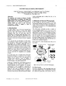
One of the features of the Interactive C programming languages is the support for multithreading. It allows control and management operations to be executed at the same time. It also allows programmers to create, disable, and enable processes as needed. There are two independent processes in the CCAM: manual and remote. If the user has selected the manual mode using the mode selection switch (see Figure 3) then the CCAM will activate the manual process and read the commands from the manual switches. Otherwise, the remote process will be enabled and the E-board reads the user commands from the parallel port of the home server. In both cases the current command will be matched against one of the home appliances and its control function will be invoked. IV. DISCUSSION A prototype was designed, built and implemented as shown in Figure 9. Three home appliances are used and interfaced to the E-board: an oven in the kitchen, a fan in the bed room, and a light in the living room. The three appliances are interfaced with the E-board and the latter is connected to the home server. The home PC-server is used to host the Webpage, JSPs and JavaBeans of the home automation systems.
Figure 9: The home automation system
503
The user accesses the system URL by typing it into any internet browser. Then the server downloads an active page as shown in Figure 7. The user then logs in using a user name and password then pressing the submit button. Using the middle.jsp page, the system validates the parameters and grants access to the home automation system as shown in Figure 8. Once the user presses the hyper-reference "Continue" in Figure 8, the request is passed to form.jsp page which displays a virtual home as shown in Figure 10. For instance, if the user wishes to turn the light ON, he/she must select the ON radio button followed by the submission button. After validating the command, the request is passed to the E-board which causes the CCAM engine to turn on the light as requested. To provide a convenient, user friendly home automation system, the CAM engine updates the user’s web interface with the home appliances latest status. For example, if the user has turned ON the fan, oven, and light, the system executes the commands accordingly and the new home status is displayed in the browser page of the user as shown in Figure 11. It is worth mentioning that the same interface page will show up when the local mode is invoked.
Figure 10. Virtual home with control buttons
IEEE Transactions on Consumer Electronics, Vol. 50, No. 2, MAY 2004
504 [2] [3] [4] [5] [6] [7] [8] [9] Figure 11. Appliances real time status status.
[10]
V. CONCLUSION A web-based home automation system was designed, implemented and tested. The system uses an off-the-self stand-alone embedded system board that can monitor and control home appliances locally without the need for internet conductivity. Once the user decides to use the remote monitoring and control activities via the World Wide Web, he/she can enable the remote access software engine to allow remote access via the server’s parallel port to monitor and control the appliances from any web bower. A software algorithm was developed using high-level languages to monitor and control the appliances locally or remotely. The system is scalable and new devices can be added with no changes to the core of the CAM engine. It only requires integrating the control unit into the CAM code. Furthermore, the systems can be access from any internet-based device including handheld devices such as PDAs and mobile phones. This is because the CAM system is based on JSPs and nothing will be loaded into the client’s device during a control session. The client interface is a simple home page with friendly Graphical User Interface (GUI). The CAM engine was developed using Java components which will not limit the system to run on specific operation system. The system allows multi-vendor appliances to be added with no major changes.
[11] [12]
[13]
[14] [15] [16]
J. C. Nunes and J. C. M. Delgado, “An Internet application for home automation,” Electrotechnical Conference, 2000. MELECON 10th Mediterranean, Vol: 1, pp. 298 -301, 2000. P. M. Corcoran, F. Papai and A. Zoldi, “User Interface Technologies for Home Appliances and Networks,” IEEE Transactions on Consumer Electronics, Vol. 44, No. 3, pp. 679-685, August 1998. P. M. Corcoran and J. Desbonnet, “Browser Style Interfaces to Home Automation Network,” IEEE Transactions on Consumer Electronics, pp. 1063-1069, November 1997. N. Sriskanthan and Tan Karande, “Bluetooth Based Home Automation Systems,” Journal of Microprocessors and Microsystems, Vol. 26, pp. 281-289, 2002. R. Shepherd “Bluetooth Wireless Technology in the Home,” Electronics & Communication Engineering Journal, Vol. 13 Issue.5, pp. 195 -203, October 2001. Wong, E.M.C, “Phone-based remote controller for home and office automation”, IEEE Transactions on Consumer Electronics, Vol. 40 No. 1, pp. 28 –34, February 1994. Ismail Coskun and H. Ardam, “A Remote Controller for Home and Office Appliances by Telephone,” IEEE Transactions on Consumer, Vol. 44, No. 4, pp. 1291-1297. November 1998. K. Tan, T. Lee and C. Yee Soh, “Internet-Based Monitoring of Distributed Control Systems-An Undergraduate Experiment,” IEEE Transactions on Education, Vol. 45, No. 2, May 2002. Chi Chung Ko, Ben M. Chen, Shaoyan Hu, Vikram Ramakrishnan, Chang Dong Cheng, Yuan Zhuang, and Jianping Chen, “A Web-Based Virtual Laboratory on a Frequency Modulation Experiment,” IEEE Transactions on Systems, Man, and Cybernetics-Part C: Application and Reviews, Vol. 31, No. 3, pp. 295-303, August 2001. N. Swamy, O. Kuljaca and F. Lewis, “ Internet-Based Educational Control Systems Lab Using Net-meeting,” IEEE Transaction on Education, Vol. 45, No. 2, pp. 145-151, May 2002. C.C. Ko, Ben M. Chen, Jianping Chen, Yuan Zhuang and Kay Chen Tan, “Development of a web-Based Laboratory for Control Experiments on a Coupled Tank Apparatus,” IEEE Transactions on Education, Vol. 44, No. 1, pp. 76-86, February 2001. C. C. Ko, B. M. Chen, J. Chen, Y. Zhuang and K. C. Tan, "Development of a Web-based laboratory for control experiments on a coupled tank apparatus", IEEE Transactions on Education, Vol. 44, No. 1, pp. 76-86, February 2001. P. Lin and H. Broberg, “HVAC Applications,” IEEE Industry Applications Magazine, pp. 49-54, January 2002. www.handyboard.com , 2003. Motorola, www.motorola.com , 2003.
A. R. Al-Ali (M’86) received his Ph.D. from Vanderbilt University, USA, 1990, Currently, He is an associate professor of computer engineering, American University of Sharjah, UAE. His area of search and teaching interests: microprocessors, microcomputers, microcontroller, embedded Systems, data acquisition units and PLC hardware/software Architectures, industrial plants remote monitoring and control using Internet, GSM, and GPRS networks. M. Al-Rousan received his Ph.D. from
REFERENCES [1]
Neng-Shiang Liang; Li-Chen Fu; Chao-Lin Wu; “An integrated, flexible, and Internet-based control architecture for home automation system in the Internet era,” Proceedings ICRA '02. IEEE International Conference on Robotics and Automation, Vol. 2, pp. 1101 –1106, 2002.
Brigham Young University, 1996, USA. He is an associate Professor of computer engineering, Jordan University of Science and Technology. Currently, he is on sabbatical leave at the American University of Sharjah, UAE. His search interest includes wireless networking, SCI, Intelligent systems and Internet Computing.