Jittering Reduction in Marker-Based Augmented Reality Systems Monica Rubio1, Arturo Quintana1, Hebert Pérez-Rosés1, Ricardo Quirós2, and Emilio Camahort3 1
Universidad de Oriente. Patricio Lumumba S/N, 90500 Santiago de Cuba, Cuba {mrubio, quintana, hebert}@csd.uo.edu.cu 2 Universitat Jaume I. Av. Sos Baynat S/N, 12071 Castellón, Spain
[email protected] 3 Universidad Politécnica de Valencia. Camino de Vera S/N, 46022 Valencia, Spain
[email protected]
Abstract. Augmented Reality systems have recently become widely used. This is due to the new open source libraries that have emerged for fast application development. In this paper we address one of the most relevant problems in this type of systems, oscillation in the camera pose estimates. We study the oscillation of a system developed using the ARToolkit library. We apply both average and Kalman filters to stabilize the estimates. Using filter substantially reduces oscillation, thus improving the system’s usability.
1 Augmented Reality Systems Augmented Reality (AR) systems are an evolution of the concept of Virtual Environment (VE). In AR systems the environment is the real world which is enhanced with virtual elements. The similarity of AR and VE systems implies that their associated problems are nearly the same. Both AR and VE systems are made of three main subsystems [1]: • Scene generator (graphics system). • Rendering devices (rendering system). • Tracking and sensing (tracking system). The scene generator synthesizes the virtual images at the right location using the information provided by the tracking system. The rendering system combines the image of the real world with the virtual elements. It then displays an enhanced image to the user. Scene generation and rendering are not the main problems of the design of effective AR systems. VEs have more restrictive requirements because of the need to render the entire virtual world in the most realistic way. In AR the virtual images complement the real world. Therefore, we need to render only a few virtual objects. These objects do not necessarily have to be realistic, as long as the requirements of the application are met. M. Gavrilova et al. (Eds.): ICCSA 2006, LNCS 3980, pp. 510 – 517, 2006. © Springer-Verlag Berlin Heidelberg 2006
Jittering Reduction in Marker-Based Augmented Reality Systems
511
The tracking system obtains the viewing parameters (position and orientation) in the real world. This subsystem has registration problems – problems with the correspondence between the real and the computed viewing parameters –. Registration problems are more important in AR systems than in EVs. In an EV the user only sees virtual objects. So, registration errors produce conflicts that can induce confusion and disorderly movements. In an AR system the conflict is visual, because the user can compare the virtual and real worlds [1]. Most of current research in AR focuses on the registration problem, the most important one when building an effective AR system [2][3]. The tracking system is primarily responsible for the registration accuracy. In the following section we survey tracking systems commonly used in AR applications. 1.1 Tracking Systems The most common AR tracking systems use either hardware sensors or computer vision techniques. There are also hybrid approaches that combine both techniques to improve registration. These systems are more complex and expensive, but they produce better results. A traditional approach to tracking the viewer is the use of hardware sensors to estimate the viewing parameters. Commercial sensors come in different types: mechanical, optical and ultrasound sensors. They have been widely used in VE interaction and have been adopted by indoor AR applications. Even though these sensors are very accurate, they require a complex infrastructure and a substantial investment. This prevents their use in certain applications, especially in the outdoors. Registration solely based on hardware sensors can be compared to an open-loop controller [4]. The system has no information to relate the real world to the virtual world. So it is difficult to obtain an accurate registration. In video based systems we can use image processing or computer vision techniques to improve registration. Computer vision techniques can be applied to tracking in two ways: (i) registration can be improved using reference points in the environment (marker based tracking), and (ii) pattern matching techniques can be used for registration [5][3]. The second approach, although promising, does not currently allow the development of effective AR systems. Marker based tracking systems add a set of reference objects to the environment. These objects are commonly called markers or fiducials. The position and features of the different markers are known. This allows estimation of the real-world viewing parameters using an inverse projection transform. The main marker-based systems in the
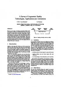
Fig. 1. Marker types. TRIP, Colored Rings, Cybercode, ARToolkit.
512
M. Rubio et al.
literature are the TRIP system (Target Recognition using Image Processing) [6], multiresolution colored rings [7], the CyberCode system [8] and the ARToolkit library [9]. Fig.1 shows example markers used by these systems. The most popular marker based tracking system is the ARToolkit library of Kato and Billinghurst [9]. ARToolkit is an open source library that supports the development of AR applications with a marker based tracking system. The advantages of ARToolkit are: (i) it is open source, (ii) it uses simple low-cost technology, (iii) it runs in real time, (iv) it supports mobile devices like phones and PDAs, and (v) it produces results accurate enough for most applications. One of the main limitations of the library is its inaccurate pose estimations. This produces a noticeable jittering, even when the camera and the markers are still. Nevertheless ARToolkit is an ideal tool for easy development of AR systems without demanding accuracy requirements. This fact is supported by the large number of applications developed using the library [10] [11], and by the celebration of conferences specifically devoted to it (First & Second IEEE International Augmented Reality Toolkit Workshops, ART’02 & ART’03).
2 Jittering in AR Systems Our research work is part of a larger project called VIRTAINER [12]. VIRTAINER develops and implements acceleration techniques for rendering ordered stacked objects. Such techniques can be applied to industrial process monitoring and virtual environment navigation. One of the goals of the project is an AR prototype system to remotely access information related to containers in a maritime terminal [13]. On order to develop our tracking system we run some tests with vision based techniques. We implemented a low-cost tracking system using a TabletPC, USB webcams and the ARToolkit library [14]. The tests showed the limitations of using ARToolkit as our tracking system. The main limitation was the poor accuracy of the pose estimations. This produces a noticeable jittering, even when the camera and the markers are still. This problem occurs because ARToolkit processes the video sequence frame by frame. This effect in our prototype can be seen in a video located at the address http://graficos.uji.es/TSCG06. The goal of our research is to reduce jittering by using filters that take into account the history of pose estimates. To achieve this goal we address the following issues: • We design techniques for pose extraction given the estimates of ARToolkit. We also analyze different pose representations. • We characterize jittering for different spatial relations between the camera and the marker. • We propose filters for pose estimates and study their effect on jittering. The rest of this section is devoted to analysing pose extraction techniques and characterizing the jittering. In the following section we present the filters applied to the tracking system to reduce jittering.
Jittering Reduction in Marker-Based Augmented Reality Systems
513
2.1 Pose Extraction ARToolkit’s tracking system runs frame by frame. For each frame the markers visible in the image are detected. Then the marker with highest confidence is selected and a transformation is returned. The transformation maps the camera coordinate system to the coordinate system of the marker selected. That transformation is stored as a 4x4 matrix MT and returned to the application for processing (see Fig. 2). Y
MT
Up Side Forward Viewpoint
λ
X
Z
Marker coordinate system
Camera coordinate system Fig. 2. Relationship between the coordinate systems of the camera and the marker. MT matrix.
Given matrix MT current AR systems use it as the OpenGL modelview matrix to render the virtual objects. That way the objects are rendered using a synthetic camera that has been registered with the real camera. Direct application of filters to matrix MT has the disadvantage that it can produce non-orthogonal matrices. So, to apply filters to the pose estimates we need to use an alternative representation for the pose. First, we consider directly extracting the camera coordinate system from matrix MT. Note that MT is a coordinate system transformation, and its first three rows contain the director vectors Forward, Up and Side. The fourth column is related to the viewing position. These relationships between MT and the camera coordinate system are illustrated in the following equation:
⎡ Sx S y Sz ⎢U U y Uz MT = ⎢ x ⎢ Fx Fy Fz ⎢ − − ⎣−
Tx ⎤ T y ⎥⎥ Tz ⎥ ⎥ −⎦
(1)
To guarantee an orthogonal pose we use a representation made of the viewpoint and the Forward and Up vectors. After applying the filters we compute Side as the cross product of Forward and Up. Then we re-compute Up as the cross product of Forward and Side. This technique is also used by the gluLookAt call of the GLU library. The first representation we consider for the pose has the following parameters: P 1 = {Tx, Ty, Tz, Fx, Fy, Fz, Ux, Uy, Uz}
(2)
Two alternative representations replace the Forward and Up vectors by three Euler angles or a quaternion. Both options support representing an orientation in 3D space. This allows conversion between them and the director vectors. To perform these conversions we use the algorithms by Shoemake published in the Graphics Gems [15].
514
M. Rubio et al.
Due to the large number of possible combinations of Euler angles, we selected the two most common combinations: XYZs (yaw, pitch y roll) used in computer graphics and navigation, and XYXr used in mechanics, where turns are made around a rotating system. These alternative representations have the following parameters: P 2 = {Tx, Ty, Tz, θ1, θ2, θ3} P 3 = {Tx, Ty, Tz, s, vx, vy, vz }
(3)
2.2 Jittering Characterization To characterize ARToolkit’s jittering under static conditions we run tests representing the pose as a local coordinate system (P1). Given the transformation matrix we extract the viewpoint (Tx, Ty, Tz), the Up vector (Ux, Uy, Uz) and the Forward vector (Fx, Fy, Fz). We analyze each of these parameters separately. For the viewpoint position the jittering amplitude is defined by the distance between two estimated positions in consecutive frames. For the orientation (Up and Forward vectors) the jittering amplitude is defined by the angle between two estimated vectors in consecutive frames. We run multiple tests to measure the jittering under different spatial relations between the camera and the marker. On one side we consider the relative distance between them expressed as the percentage of the image covered by the marker. For each distance there are three possible angular relations per coordinate axis between the marker and the camera. We place the marker facing the camera (0º) or tilted 45º and 65º with respect to the X and Y axes. Altogether we have 9 different angular relations. Fig. 3 shows some of the relations used. Combining 9 angular and 2 distance relations requires running 18 tests. Table 1 show average, maximum and standard deviation numbers for the jittering amplitude for both camera position and Up and Forward vectors. For brevity, we only show a
Fig. 3. Different camera-marker relations (setups) used in our tests Table 1. Jittering amplitude measurements for different camera-marker relations Spatial relation 12% / 00 / 00 12% / 450 / 450 12% / 650 / 650 25% / 00 / 00 25% / 450 / 450 25% / 650 / 650
Med
Up Max
σ
Med
.0244 .0021 .0009 .0034 .0010 .0003
.0970 .0076 .0029 .0155 .0037 .0013
.0183 .0012 .0004 .0023 .0005 .0002
.0333 .0024 .0011 .0037 .0012 .0004
Forward Max σ .1128 .0076 .0034 .0155 .0034 .0015
.0199 .0012 .0005 .0023 .0006 .0002
Med
Position Max
σ
1.437 .7180 .2450 .2093 .1899 .0531
7.928 2.821 .9129 .8082 .7461 .2154
1.231 .4827 .1516 .1342 .1318 .0315
Jittering Reduction in Marker-Based Augmented Reality Systems
515
few of the combinations we tested. Results for all combinations can be found at the address http://graficos.uji.es/TSCG06. Table 1 shows that jittering amplitude is reduced for all parameters when: (i) the size of the marker in the image increases or (ii) the magnitude of the angles increases. With this characterization of jittering we select one of the combinations with the worst jittering (12% / 0º / 0º). With this combination we test the filters we implement for our tracking system.
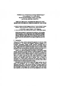
3 Filtering the Pose Estimate To stabilize the pose estimated by ARToolkit we have to add to our system filters that take into account the recent history of estimates. A filter commonly used to stabilize noisy signals is the average filter. We use it to average the estimates of the last 6 and 12 frames. Alternatively, other authors propose the use of the Kalman filter. The Kalman filter is a predictive recursive filter designed to estimate the state of dynamic systems [16]. The filter algorithm predicts the new state given a previous estimate and applying a correction term proportional to the prediction error. This way the error is statistically minimized. We use the implementation of the Kalman filter contained in Intel’s OpenCV library [17]. This implementation provides a data structure and the functions needed to make predictions and to correct the state with the measurements. 3.1 Experimental Results We have tested the application of average and Kalman filters to the position and orientation estimates provided by ARToolkit. For the orientation we consider the three possible representations (P1, P2, P3). To effectively compare the filters we always end up converting all other pose representations to a local coordinate system (P1 representation). This way all the results of our filter tests can be presented as the change of the viewpoint and the Up and Forward vectors between two consecutive frames. Experiments were run with a 1000-frame video. Now we show graphically the original jittering and the jittering after applying the three filters: 6-frame average, 12-frame average and Kalman. Each of the following plots shows a subset of the experiment (80 consecutive frames) for each of the pose parameters: viewpoint, Up vector and Forward vector. There are four sets of plots, one for each possible orientation representation. Fig. 4 shows the results obtained for a local origin viewpoint and for director vectors (P1 representation) extracted from the matrix estimated by ARToolkit. In the plots we observe that for the Up and Forward vectors the best filter is the 12frame average, followed by the 6-frame average and Kalman. For the viewpoint, however, the Kalman filter behaves better. Its average variation is in the interval 10-2 - 10-3. The results obtained with the other two representations, P2 and P3 are similar. In any case, the best results for the orientation are obtained with the 12-frame average filter. All the plots we generated with our tests can be found at the address http://graficos.uji.es/TSCG06.
516
M. Rubio et al.
/
/
Original
Average 6 frames
/
Average 12 frames
Kalman
Fig. 4. Results of applying the different filters implemented to reduce jittering. Left, viewpoint, center, Up vector, right, Forward vector, and bottom, zoomed-in version of the top row plots.
In addition to the plots, we compared the different pose representations. For each filter we plotted the jittering amplitude for the different representations. For the average filters, the representation did not make a difference. When using the Kalman filter there are differences. Since orientation stabilizes better with average filters, we do not find these differences relevant. All the plots with the comparisons between representations can be found at the address http://graficos.uji.es/TSCG06.
4 Conclusions In this paper we present methods to reduce jittering in maker based AR systems. We have defined three different pose representations: local coordinate system, Euler angles and quaternions. We have implemented average and Kalman filters and we have applied them to the pose estimated by ARToolkit. We have run tests and our results show that all filters reduce jittering. Recall that all the running times of the filters are acceptable. The system runs in real time whether filters are used or not. We conclude that the best filter configuration is a Kalman filter for the viewpoint and an average filter for the orientation represented as a local coordinate system. We use this configuration in our AR system. A video showing our system running with and without filters can be found at the address http://graficos.uji.es/TSCG06.
Acknowledgments This work was partially supported by grants TIC2002-4166-C03 and TIN2005-08863C03 of the Spanish Ministry of Science and Education and by a STREP project IST004363 of the 6th Framework Program of the European Union.
Jittering Reduction in Marker-Based Augmented Reality Systems
517
References 1. Azuma, R. T.: A Survey of Augmented Reality. Presence: Teleoperators and Virtual Environments” 6, 4 (1997) 355–385 2. Auer, T.: Hybrid Tracking for Augmented Reality. Graz University of Technology (2000) 3. Comport, A., Marchand, E., Chaumette, F.: Robust and real-time image-based tracking for markerless augmented reality. Technical report, 4847, INRIA (2003) 4. Bajura, M., Ulrich, N.: Dynamic Registration Correction in Video-Based Augmented Reality Systems. IEEE Computer Graphics and Applications 15, 5 (1995) 52–60 5. Behringer, R.: Improving Registration Precision through Visual Horizon Silhouette Matching. IEEE International Workshop on Augmented Reality (1998) 225–232 6. López de Ipiña, D., Mendonça, P. R. S., Hopper, A.: TRIP: a Low-Cost Vision-Based Location System for Ubiquitous Computing. Personal and Ubiquitous Computing 6, 3 (2002) 206–219 7. Cho, Y., Lee, J., Neumann, U.: Multi-ring Color Fiducial Systems and An IntensityInvariant Detection Method for Scalable Fiducial Tracking Augmented Reality. IEEE International Workshop on Augmented Reality (1998) 8. Rekimoto, J., Ayatsuka, Y.: CyberCode: Designing Augmented Reality Environments with Visual Tags. Proceedings of DARE 2000 on Designing augmented reality environments (2000) 1–10 9. Kato, H., Billinghurst, M., Poupyrev, I.: ARToolkit Version 2.33 Manual (2000) 10. Billinghurst, M., Kato, H., Poupyrev, I.: The Magic-Book. Moving Seamlessly between Reality and Virtuality. IEEE Computer Graphics and Applications, 21, 3 (2001) 2–4 11. Prince, S., Cheok, A. D. Farbiz, F., Williamson, T., Johnson, N., Billinghurst, M., Kato, H.: 3D Live: Real Time Captured Content for Mixed Reality. International Symposium on Mixed and Augmented Reality (2002) 7–13 12. Escrivá, M., Martí, M., Sánchez, J. M., Camahort, E., Lluch, J., Vivó, R.: Virtainer: Graphical Simulation of Container Storage Yard with Dynamic Portal Rendering. Proceedings of the Ninth International Conference on Information Visualisation (2005) 773–778, 13. Rubio, M., Quirós, R., Pulido, E.: Annotation of Features in Outdoor Augmented Reality Enviroments. 7th Conference on Geographic Information Science (2004) 243–250 14. Rubio, M., Quirós, R., Pulido, E., Huerta, J., Camahort, E.: Wide Area Marker Based Tracking. Intl. Conf. on Visualization, Imaging & Image Processing (2005) 655–659 15. Shoemake, K.: Euler angle conversion. Graphics gems IV, Academic Press (1994) 222– 229 16. Welch, G., Bishop, G.: An Introduction to the Kalman Filter. SIGGRAPH 2001 Course 8. ACM Press (2001) 17. Open Source Computer Vision Library Reference Manual. © Intel (1999-2001)