Zero vector of N elements ... in [6] embracing the most reasonable optimization criteria for ... where Tcs and Tc are respectively the data symbol period and.
The 18th Annual IEEE International Symposium on Personal, Indoor and Mobile Radio Communications (PIMRC’07)
JOINT LINEAR PRECODER-DECODER OPTIMIZATION OVER MIMO-CDMA MULTIPATH CHANNELS Xiaolei Wang and Athanassios Manikas Communications and Signal Processing Research Group Department of Electrical and Electronic Engineering Imperial College London, SW7 2AZ, UK A BSTRACT This paper addresses the problem of joint transmitter-receiver optimization in the downlink Multiple Input Multiple Output (MIMO) DS-CDMA systems over multipath fading channels. Both the transmitter and the receivers are equipped with antenna arrays and the precoding/decoding matrices can be designed to minimize the overall mean-squared-error (MSE) of the system subject to power constraint. The study is based on the Spatio-Temporal ARray (STAR) manifold concept. The performance of the proposed algorithm is supported by numerical simulations. NOTATION a, A a, A A IN 0N diag (A) Tr (A) ⊗ (•)H T (•) E{•}
Scalar Column Vector Matrix Identity matrix of N × N dimension Zero vector of N elements Diagonal matrix formed from vector A Trace of matrix A Kronecker product Hermitian transpose Transpose Expectation Operator I.
INTRODUCTION
MIMO systems using antenna arrays at both receiver and transmitter, have shown great potential to provide high bandwidth efficiency [1]. In a single-stream multiple-access environment, numerous receiver and/or transmitter beamforming schemes have been developed to efficiently enhance the signals of the desired user while minimizing the effects of multiaccess-interference (MAI) from other users and inter-symbolinterference (ISI) caused by frequency-selective channel [2][5]. Recently, the receiver-transmitter optimization in the multiple-stream multiple-access environment has received much attention. A generalized framework has been proposed in [6] embracing the most reasonable optimization criteria for multicarrier MIMO design. The most popular optimization method is zero-forcing [3][7], which normally requires the number of the transmit antennas to be larger than the sum of the number of receive antennas. Another category of MIMO system design is interference balancing [4]-[5], which normally uses generalized eigendecomposition to obtain suboptimal solutions. The optimal transmit power allocation is carried out c 1-4244-1144-0/07/$25.00°2007 IEEE
separately using, e.g. water-filling method [7]. In this paper, the problem under consideration is joint precoding-decoding optimization, including the power allocation, in a MIMO-CDMA system over multipath fading channels. The study will be based on the Spatio-Temporal ARray (STAR) manifold concept, which has been developed [8] to conduct blind superresolution channel estimation and multipleaccess interference suppression. A downlink multiuser antenna array CDMA system is modelled in Section II. In Section III, an upper-bound of the signal-to-noise-plus-interference ratio (SNIR) is given and an iterative algorithm is proposed for joint precoding-decoding optimization based on the overall MSE criterion. In Section IV, numerical simulations are presented and the paper is concluded in Section V. II.
C HANNEL M ODELLING
Consider the downlink of an M -user asynchronous MIMOCDMA wireless communication system operating in a multipath propagation environment. The receiver (mobile station) employs an array of N antennas whereas each transmitter (base station) is equipped with an array of N antennas1 . It is assumed that the channel is frequency-selective with a delay spread less than one data symbol period. Using the demultiplexer, the data sequence of the ith user (s) becomes a sequence of data vectors of Ni elements, de(s) noted by bi [n] ∈ C Ni ×1 . The data vectors bi [n] of the ith user are then spread with a unique spreading code [αi [k] = ±1, k = 1, · · · , Nc − 1] of period Nc and precoded using the matrix Wi before transmission. The overall baseband transmitted signal associated with all M users is given by m (t) =
M X i=1
with
Wi
∞ X
n=−∞
bi [n]
NX c −1 k=0
αi [k] p (t − nTcs − kTc )
nTcs + kTc ≤ t ≤ nTcs + (k + 1)Tc
(1)
where Tcs and Tc are respectively the data symbol period and the chip period, αi [k] = ±1 ( ith user’s PN sequence of period Nc = Tcs /Tc ) and p (t) is the unit amplitude rectangular chip waveform. It is important to point out that the average power th of the transmitted ³ H ´signal of the i user can be expressed by P i = Tr Wi Wi . Let us assume plane-wave propagation with the transmitted signal arriving at the ith receiver via Ki paths (multipath). Furthermore, consider that the j th path of the ith user’s direction of 1 Note that a symbol with a ‘bar’ at the top will denote a transmitter’s parameter.
The 18th Annual IEEE International Symposium on Personal, Indoor and Mobile Radio Communications (PIMRC’07)
departure (DOD) and direction of arrival (DOA) are denoted as follows: ¢ ¡ • DOD: (azimuth, elevation) = θij , ϕij ¡ ¢ • DOA: (azimuth, elevation) = θij , ϕij
Based on the channel model shown in Fig. 1, the received complex baseband signal vector at the antenna array of the receiver (point I) can be expressed explicitly as xi (t) =
Ki X j=1
H
β ij S ij S ij m (t − τ ij ) + ni (t)
(2)
where β ij and τ ij represent the fading coefficient and the delay of the j th path of the ith user, and ni (t) denotes the complex white Gaussian noise vector with zero mean and covariance matrix σ2 IN . The vector S ij represents array manifold vector of the receiver associated with the j th path of the ith user and can be formulated as follows S ij , exp(−j · [rx , ry , rz ] · kij )
(3)
where [rx , ry , rz ] ∈ RN ×3 denotes the Cartesian coordinates of the antenna array elements of the receiver and kij = (2πFc /c) · [cos θij cos ϕij , sin θij cos ϕij , sin ϕij ]T (4) is the wavenumber vector pointing towards the DOA of the j th path of the ith user. The array manifold vector of the transmitter associated with the j th path of the ith user is denoted by S ij and can be defined in a similar fashion to Eqn. (3) but with the parameters associated with the transmitters. Without loss of generality, the elevation angle is assumed equal to zero in this paper. At point J of Fig. 1, the baseband received signal vector x (t) is initially sampled with a period Ts = Tc , and then passed through a bank of N tapped-delay lines (TDL) (see [8] for more details). The contents of a bank of N tapped delay lines (TDL), each of length 2Nc , are concatenated to obtain the vector h iT ∈ C 2N Nc ×1 xi [n] = xi,1 [n]T , · · · , xi,N [n]T (5) where xi,k [n] ∈ C 2Nc ×1 , k = 1, · · · N , represents the contents of the TDL at ith receiver’s k th antenna associated with the nth data-symbol period. To model the above, we introduce the STAR manifold vector for the k th path arriving at the ith receiver with respect to (w.r.t.) the transmitted signal of the ξ th user: ¡ ¢ S ik ⊗ Jlik cξ (6) ∈ C 2N Nc ×1 where cξ ∈ C 2Nc ×1 is the ξ th user’s spreading code sequence padded with zeros of length Nc as £ ¤T (7) cξ , αξ [0] , αξ [1] , · · · , αξ [Nc − 1] , 0TNc
and the matrix J (or JT ) is a 2Nc × 2Nc time down-shift (or up-shift) operator defined by ¸ ∙ T 0 02Nc −1 . (8) J, I2Nc −1 02Nc −1
Figure 1: Arrayed MIMO Channel of the ith user. Using the STAR manifold vector defined by (6), the STAR manifold matrix Hi,ξ ∈ C 2NNc ×Ki associated with all the Ki paths is defined as £ ¡ ¡ ¢ ¢ ¤ , (9) Hi,ξ = S i1 ⊗ Jli1 cξ , · · · , S iKi ⊗ JliKi cξ
and contains all the components that are intended for the ξ th receiver but received by the ith receiver. In addition, by defining the composite channel matrix ³ ´ H Gi,ξ = Hi,ξ diag β i Si ∈ C 2NNc ×N (10) and the two matrices associated with the previous and next symbols ³ ³ ´ H ¡ ¢Nc ´ (prev) ∈ C 2N Nc ×N Gi,ξ = IN ⊗ JT Hi,ξ diag β i Si (11) ³ ´ H ¡ ¢ (next) ∈ C 2N Nc ×N Gi,ξ = IN ⊗ JNc Hi,ξ diag β i Si (12) where £ ¤T β i = β i1 , β i2 , · · · , β iKi ∈ C Ki ×1 (13) Si =
£
S i1 , S i2 , · · · , S iKi
¤
∈ C N ×Ki
(14)
the sampled baseband signal vector xi [n] can be rewritten as ⎡ ⎤ M h bξ [n − 1] i¡ X ¢ (prev) (next) Gi,ξ , Gi,ξ , Gi,ξ I3 ⊗Wξ ⎣ bξ [n] ⎦ xi [n] = ξ=1 bξ [n + 1] +ni [n]
(15)
The 18th Annual IEEE International Symposium on Personal, Indoor and Mobile Radio Communications (PIMRC’07)
where ni [n] ∈ C 2N Nc ×1 denotes the sampled noise vector. By applying the unit-normalized decoding matrix Wi ∈ (s) 2N Nc ×Ni , i = 1, · · · , M to the sampled baseband signal C vector xi [n], the corresponding soft decision variable ˆbi [n] is obtained, ˆb [n] = WH x [n] (16) i i i
where wij is ith user’s transmit precoding vector w.r.t. the j th stream, and ⎛ (s) ⎞ Ni X ⎠ GH wiη wH (22) Mi , Mij − Gi,i ⎝ i,i . iη η6=j,η=1
Proof. The proof of this lemma uses the Cauchy-Schwarz Inequality (0.6.3 in [9]) and the inversion lemma:
III.
I TERATIVE P RECODER -D ECODER O PTIMIZATION (s)
(s)
When the numbers of substream N1 , · · · , NM are predefined, the overall system performance will be determined by the selection of precoders Wi and decoders Wi , i = 1, · · · , M . It should be noted that, the optimization of transmit power allocation among different users is absorbed by the optimization of Wi . Consider the covariance matrix of the ith MS’s received baseband signal vector xi [n]. That is © ª Rxx,i , E xi [n] xH (17) i [n]
Based on Eqn. (15), Rxx,i can be rewritten as follows, Rxx,i
=
M h X ξ=1
(prev)
Gi,ξ
(next)
, Gi,ξ , Gi,ξ
ih
³ ´i H I3 ⊗ Wξ Wξ
iH h (prev) (next) + σ 2i I2N Nc . Gi,ξ , Gi,ξ , Gi,ξ
(18)
The SNIR at the j th output of the ith user’s receiver, i = (s) 1, 2, · · · , M , j = 1, 2, · · · , Ni is given by ¯ ¯ H ¯w Gi,i wij ¯2 ij , (19) SNIRij = wH ij Mij w ij where wij and wij are the j th column of decoding matrix Wi and precoding matrix Wi , respectively. The matrix Mij takes into account the effect of MAI, ISI, noise, and interference introduced by desired user’s other transmitted data streams (desired user = ith user).and is defined as follows: ⎛ (s) ⎞ Ni X ⎠ GH Mij = Gi,i ⎝ wiη wH i,i iη
(A + u v H )−1 = A−1 −
A−1 u v H A−1 . 1 + v H Au
and is omitted here because of the lack of space. In this study, the design objective is to optimize the precoders and decoders to improve the transmit reliability (e.g., MSE) subject to the power constraint, M X i=1
³ H ´ Tr Wi Wi ≤ P .
(23)
In this case, the MSE matrix of the ith user is defined as ½³ ´³ ´H ¾ ˆb [n] − b [n] ˆb [n] − b [n] , (24) Ei , E i i i i
which can be rewritten as ³ ´−1 H −1 Ei = IN (s) + Wi GH . i,i Mi Gi,i Wi
(25)
i
Given the total transmit power, the optimization problem can be expressed as M X
min
Tr (Ei ) (W1 ,··· ,WM ; W1 ,··· ,WM ) i=1 ³ H ´ M P s.t. Tr Wi Wi ≤ P
(26)
i=1
Note that by comparing Eqn. (21) and (25), the SNIR and MSE can be connected by ³ ´ SNIRij ≤ E−1 (27) i − IN (s) i
jj
where (A)jj stands for the j th diagonal element in the square η6=j,η=1 matrix A. h i³ ´h iH It is assumed in this study that both the transmitter and reH (prev) (next) (prev) (next) + Gi,ξ , Gi,ξ I2 ⊗Wi Wi Gi,ξ , Gi,ξ ceiver have perfect knowledge of the channel, recalling the total MSE minimization object function given in (26), assuming all M ³ h i h ´i X H (prev) (next) + I3 ⊗ Wξ Wξ Wi , i ∈ [1, M ] are fixed, the cost function (using Lagrangian Gi,ξ , Gi,ξ , Gi,ξ multiplier) can be expressed as follows, ξ6=i,ξ=1 h iH (prev) (next) M M ³ H ´ X X + σ 2i I2NNc . (20) Gi,ξ , Gi,ξ , Gi,ξ J= Tr (Ei ) + μ( Tr Wi Wi − P ) (28) i=1 i=1 When the precoding matrices are fixed, the following Lemma gives the upper-bound of the SNIR threshold. ∂J In this case, ∀i ∈ [1, M ], by defining the first derivative ∂W i Lemma 1 The SNIR at the output the j th stream of the ith re- evaluated at the local optimal solution Wi , i.e. −1 H ceiver is upper-bounded by wH ij Gi,i Mi Gi,i w ij , i.e. ³ ∗ ´ µ ∂J ¶ (s) F ∈ C N×Ni , (29) i Wi = −1 H H (21) SNIRij ≤ wij Gi,i Mi Gi,i wij ∂Wi Wi =W∗i
The 18th Annual IEEE International Symposium on Personal, Indoor and Mobile Radio Communications (PIMRC’07)
³ ∗ ´ the necessary condition for Wi , μ being the solution of the optimization problem ´ ³ ∗ Wi , μ∗ = arg min (J) (30) Wi ,μ
is that:
³ ∗´ v H Fi Wi v = 0, ∀v 6= 0.
(31)
which finally results in a matrix with Wiener filter form: ∗
= {LH (
Wi
M h X
(prev)
(next)
Gξ,i , Gξ,i , Gξ,i
ξ=1
iH
Wξ WH (32) ξ
i h (prev) (next) }−1 GH )L + μI−1 Gξ,i , Gξ,i , Gξ,i i,i Wi N where L =13 ⊗ IN ∈ R3N×N . Eqn. (31) can also lead to the expression of the Lagrangian multiplier μ∗
μ∗
M 1 X H Tr{Wi GH i,i Wi P i=1
=
(33)
M h iH X H (prev) (next) −Wi LH ( Gξ,i , Gξ,i , Gξ,i ξ=1
h i (prev) (next) Wξ WH )LWi } ξ Gξ,i , Gξ,i , Gξ,i
Similarly, if the precoding matrices is fixed, the optimal decoding matrices that minimize the total MSE can be derived
2. For each user i = 1, · · · , M , the MMSE weight vector (q) Wi is calculated using Eqn. (34). 3. For the current precoders and decoders, the Lagrangian multiplier μ(q) is calculated using Eqn. (33). (q)
4. Using receive decoder matrices Wi and μ(q) obtained in Step 2 and 3 respectively, the transmit precoder matrices (q+1) Wi can be updated via Eqn. (32). 5. q ←− q + 1, repeat Steps 2-4 until a predefined convergence criterion is reached. A similar iterative method to optimize the precoder and decoder in the flat-fading downlink of the multiuser MIMO systems has been proposed recently [10]. However, in [10], brute search is needed to find the optimum Lagrangian multiplier in each iteration procedure. On contrast, the Lagrangian multiplier in our proposed iterative scheme is directly calculated with the channel information and the precoders and decoders obtained in the last iteration, which significantly reduces the algorithm’s complexity. The convergence of this proposed scheme is supported by the simulations in Section V. Please note that without power allocation, the cost function of optimization problem (26) can be rewritten as J=
M X
Tr (Ei ) +
i=1
M X i=1
³ H ´ μi (Tr Wi Wi − P i )
(36)
and the solution can be obtained in a similar fashion. Convergence of the LM-based iteration 3
W∗i
= {
(prev)
Gi,ξ
(next)
, Gi,ξ , Gi,ξ
ξ=1
ih
³ ´i H I3 ⊗ Wξ Wξ
h iH (prev) (next) +σ 2i I2LN }−1 Gi,i Wi(34) Gi,ξ , Gi,ξ , Gi,ξ
From the above analysis, it can be seen that the transmitter precoder and the receiver decoder as well as the Lagrangian Multiplier are functions of each other, thus an iterative algorithm is suggested to obtain the solution. The joint transmitterreceiver optimization can be accomplished via the following steps: 1. Initialization: the iterative index q = 0; for each user i = 1, · · · , M , Wi is constructed by single user transmit scheme, i.e., (0)
Wi
P
=
(s)
M Ni
Ui,N (s)
1.5
1
0.5
0
0
10
20
30
40 50 Iteration loop
60
70
80
90
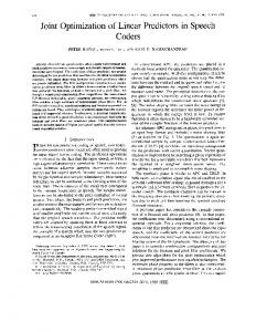
Figure 2: Convergence studies for the proposed iterative method with transmit SNR=8, 16, 24 dB in a 6 user MIMOCDMA system.
(35)
(s)
are the general
i
eigenvectors of matrix pair GH i,i Gi,i corresponding to the (s)
2
i
where the columns of Ui,N (s) ∈ C N ×Ni Ni
Transmit SNR = 8 dB Transmit SNR = 16 dB Transmit SNR = 24 dB
2.5 Average MSE per substream
M h X
largest general eigenvalues. The scalar factor
P (s) MNi
is to distribute transmitting energy evenly to every user and then every substream.
IV.
N UMERICAL S TUDIES
In this section, the performance of the joint optimization algorithm proposed in last sections is investigated through a number of numerical simulations. The transmit array considered in the simulation is a 6-element ULA and all the receiver arrays are 2-element ULA, both with half-wavelength spacing. Each
The 18th Annual IEEE International Symposium on Personal, Indoor and Mobile Radio Communications (PIMRC’07)
10
BER vs Total Transmit SNR
0
10
BER vs Total Transmit SNR
0
Eigen + RAKE Eigen + MMSE No Power Allocation Central Power Allocation 10
Eigen + RAKE Eigen + MMSE No Power Allocation Central Power Allocation
-1
10
-2
10
10
10
-1
Average BER
Average BER
10
-2
-3
-4
-10
-5 0 Average Transmit SNR Per User (dB)
5
10
Figure 3: BER performance of the proposed iterative algorithm (by 30 iterations) with and without power allocation, and the eigendecomposition-based transmit precoding with RAKE/MMSE receive decoding. There are 6 users in the MIMO-CDMA system. user employs a unique Gold sequence of length Nc = 15, and (s) transmit Ni = 2 substreams. Signals are transmitted to the receiver via Ki = 3 multipaths. The DOD and DOA of each multipath are randomly selected from [0, 180◦ ). and the TOA are randomly selected from [0, 15Tsc ).The array is assumed to collect a block of 200 data symbols for processing at each time, during which the channel is assumed to be stationary with the channel state information available to both BS transmitter and mobile receivers. Firstly the convergence curve of the proposed iteration schemes is studied for various transmitP SNR levels in a 6-user MIMO-CDMA scenario. Note that as M 1 Ni = 12 > N , the condition of conventional zero-forcing approach is no longer satisfied. The numerical results representing the average MSE over all substreams for all users are shown in Fig. 2 as the function of the iteration loops by which the precoders and decoders are iteratively obtained. From Fig. 2 it is clear that the convergence property of the proposed algorithm improves with the SNR. In Fig. 3 and Fig. 4, the BER performance of the proposed iterative algorithm (with or without power distribution) is compared with an extension of the precoding scheme proposed in [5]. In particular, the precoder is based on generalized eigendecomposition and the decoder on the RAKE and MMSE receivers. From these two figures, it is clear that the proposed iterative algorithm with power allocation achieves the best performance. Furthermore, even the proposed algorithm without power allocation outperforms the conventional scheme (based on eigendecomposition and MMSE receiver) when the number of users is large. V.
C ONCLUSION
In this paper, the problem of joint precoding and decoding optimization in a MIMO-CDMA system over multipath fading channels has been studied. It has been shown that by utilizing
10
-3
-15
-10
-5 0 5 Average Transmit SNR Per User (dB)
10
15
Figure 4: The same as Fig. 3 except there are 10 users in the MIMO-CDMA system. the STAR manifold concept, the channel can be properly exploited in both space and time domain. The proposed approach is based on minimizing the overall MSE under the power constraint and an iterative solution to the overall MSE optimization problem is provided and supported by simulation results. R EFERENCES [1] G. J. Foschini and M. J. Gans, “On limits of wireless communications in a fading environment when using multiple antennas,” Wireless Personal Commun., no. 6, pp. 311–335, 1998. [2] W. Xiaodong and H. V. Poor, “Blind multiuser detection: a subspace approach,” Information Theory, IEEE Transactions on, vol. 44, no. 2, pp. 677–690, 1998. [3] U. Lai and R. D. Murch, “A transmit preprocessing technique for multiuser mimo systems using a decomposition approach,” Wireless Communications, IEEE Transactions on, vol. 3, no. 1, pp. 20–24, 2004. [4] Z. Shengli and G. B. Giannakis, “Optimal transmitter eigenbeamforming and space-time block coding based on channel correlations,” Information Theory, IEEE Transactions on, vol. 49, no. 7, pp. 1673–1690, 2003. [5] A. Tarighat, M. Sadek, and A. H. Sayed, “A multi user beamforming scheme for downlink mimo channels based on maximizing signal-toleakage ratios,” vol. 3, pp. iii/1129–iii/1132, 2005. [6] D. P. Palomar, J. M. Cioffi, and M. A. Lagunas, “Joint tx-rx beamforming design for multicarrier mimo channels: a unified framework for convex optimization,” Signal Processing, IEEE Transactions on [see also Acoustics, Speech, and Signal Processing, IEEE Transactions on], vol. 51, no. 9, pp. 2381–2401, 2003. [7] Q. H. Spencer, A. L. Swindlehurst, and M. Haardt, “Zero-forcing methods for downlink spatial multiplexing in multiuser mimo channels,” Signal Processing, IEEE Transactions on [see also Acoustics, Speech, and Signal Processing, IEEE Transactions on], vol. 52, no. 2, pp. 461–471, 2004. [8] A. Manikas and J. W. P. Ng, “Crossed-dipole arrays for asynchronous dscdma systems,” IEEE Trans. Antennas Propogat., vol. 52, no. 1, pp. 122– 131, 2004. [9] R. A. Horn and C. R. Johnson, Matrix Analysis. Cambridge, U.K.: Cambridge Univ. Press, 1990. [10] Z. Jinfan, W. Yongle, Z. Shidong, and W. Jing, “Joint linear transmitter and receiver design for the downlink of multiuser mimo systems,” Communications Letters, IEEE, vol. 9, no. 11, pp. 991–993, 2005.