Joint Modeling and Design of Wireless Networks and Sensor Node Software
Elaine Cheong Edward A. Lee Yang Zhao
Electrical Engineering and Computer Sciences University of California at Berkeley Technical Report No. UCB/EECS-2006-150 http://www.eecs.berkeley.edu/Pubs/TechRpts/2006/EECS-2006-150.html
November 17, 2006
Copyright © 2006, by the author(s). All rights reserved. Permission to make digital or hard copies of all or part of this work for personal or classroom use is granted without fee provided that copies are not made or distributed for profit or commercial advantage and that copies bear this notice and the full citation on the first page. To copy otherwise, to republish, to post on servers or to redistribute to lists, requires prior specific permission. Acknowledgement This work was supported in part by the Center for Hybrid and Embedded Software Systems (CHESS) at UC Berkeley, which receives support from the National Science Foundation (NSF award #CCR-0225610), the State of California Micro Program, and the following companies: Agilent, DGIST, General Motors, Hewlett Packard, Infineon, Microsoft, National Instruments, and Toyota.
Joint Modeling and Design of Wireless Networks and Sensor Node Software Elaine Cheong
Edward A. Lee
Yang Zhao
Department of EECS University of California Berkeley, CA 94720 USA
Department of EECS University of California Berkeley, CA 94720 USA
Department of EECS University of California Berkeley, CA 94720 USA
[email protected] [email protected] ABSTRACT We present Viptos (Visual Ptolemy and TinyOS), a joint modeling and design environment for wireless networks and sensor node software. Viptos is built on Ptolemy II, a graphical modeling and simulation environment for embedded systems, and TOSSIM, an interrupt-level discrete event simulator for homogeneous TinyOS networks. Viptos includes the full capabilities of VisualSense, a Ptolemy II environment that can model communication channels, networks, and non-TinyOS nodes. Viptos presents a major improvement over VisualSense by allowing developers to refine highlevel wireless sensor network simulations down to real-code simulation and deployment, and adds much-needed capabilities to TOSSIM by allowing simulation of heterogeneous networks. Viptos provides a bridge between Ptolemy II and TOSSIM by providing interrupt-level simulation of actual TinyOS programs, with packet-level simulation of the network, while allowing the developer to use other models of computation available in Ptolemy II for modeling the physical environment and other parts of the system. This framework allows application developers to easily transition between high-level simulation of algorithms to low-level implementation, simulation, and deployment. In this paper, we discuss how we integrate the semantics of two different simulation systems. We show that the Viptos simulator performance scales linearly in the number of nodes, and even without aggressive performance tuning, can simulate moderately large, heterogeneous sensor networks effectively.
1.
INTRODUCTION
Wireless sensor networks provide a way to create flexible, tetherless, automated data collection and monitoring systems. Building sensor networks today requires piecing together a variety of hardware and software components, each with different design methodologies and tools, making it a challenging and error-prone process. Typical networked embedded system software development may require the design and implementation of device drivers, network
ellen
[email protected]
stack protocols, scheduler services, application-level tasks, and partitioning of tasks across multiple nodes. Little or no integration exists among the tools necessary to create these software components, mostly because the interactions between the programming models are poorly understood. In addition, these tools typically have little infrastructure for building models and interactions that are not part of their original scope or software design paradigms. The goal of this work is to create integrated tools for networked embedded application developers to model and simulate their algorithms and quickly transition to testing their software on real hardware in the field, while allowing them to use the programming model most appropriate for each part of the system. We choose to focus on TinyOS [8], an open-source runtime environment designed for sensor network nodes known as motes, as our underlying programming platform. TinyOS has a large user base – over 500 research groups and companies use TinyOS on the Berkeley/Crossbow motes. It has been ported to over a dozen platforms and numerous sensor boards, and new releases see over 10,000 downloads. TinyOS differs from traditional operating system models in that events drive the behavior of the system. Using this type of execution, battery-operated nodes can preserve energy by entering sleep mode when no interesting events are happening. In this paper, we focus on TinyOS 1.x; we discuss TinyOS 2.x in Section 5. A TinyOS program consists of a graph of components that are written in an object-oriented style using nesC [4], an extension to the C programming language. TOSSIM [12], a TinyOS simulator for the PC, can execute nesC programs designed for a mote. TOSSIM contains a discrete event simulation engine which allows modeling of various hardware and other interrupt events. Although a large community uses TinyOS in simulation to develop and test various algorithms and protocols, they face some key limitations when using the nesC/TinyOS/TOSSIM programming toolsuite. Users may choose from a few built-in radio connectivity models in TOSSIM, but it is difficult to use other models. TOSSIM can efficiently model large homogeneous networks where the same nesC code is run on every simulated node, but does not allow simulation of networks that contain different programs. Additionally, a TinyOS program consists of a graph of mostly pre-existing nesC components; users must write their programs in a multi-file, text-based format, even though a graphical block diagram programming environment would be much more intuitive. To address these problems, we consider VisualSense [1], a
Ptolemy II-based graphical modeling and simulation framework for wireless sensor networks that supports actor-oriented definition of sensor nodes, wireless communication channels, physical media such as acoustic channels, and wired subsystems. Ptolemy II is a modeling, simulation, and design environment for hierarchical, concurrent, real-time, and embedded systems. VisualSense mainly provides an abstract, mathematically-based modeling environment, and node models must be created from scratch. VisualSense does not provide a mechanism for transitioning from a sensor network application developed within the framework to an implementation for real hardware without rewriting the code from scratch for the target platform. Integrating TinyOS and VisualSense combines the best of both worlds. TinyOS provides a platform that works on real hardware with a library of components that implement lowlevel routines. VisualSense provides a graphical modeling environment that supports hierarchical, heterogeneous systems. In this paper, we present Viptos (Visual Ptolemy and TinyOS), a tool for joint modeling and design of wireless networks and actual sensor node software. This paper has three main contributions. First, it addresses a need for a unified wireless sensor network development environment that allows abstract modeling and refinement to low-level simulation and deployment. Second, it provides insights into the integration of the semantics of two different simulation systems, with different representations of software components, programming languages, types systems, and schedulers. Third, it shows through evaluation that the implementation of the combined system is linearly scalable in the number of nodes. We describe the architecture of the integrated TinyOS and Ptolemy II toolchain and investigate the semantics of this interface in section 2. We evaluate the performance of Viptos in Section 3. We present related work in Section 4. We discuss design choices and areas for future work in Section 5, and conclude in Section 6.
2.
DESIGN
Viptos provides a bridge between Ptolemy II and TinyOS by enabling the graphical development and interrupt-level simulation of actual TinyOS programs, with packet-level simulation of the network, while allowing the developer to use other models of computation available in Ptolemy II for modeling various parts of the system. We describe the architecture of this integrated system in detail, including the representation of nesC components, the transformation of the nesC components into this representation, the generation of code for TinyOS programs developed in Viptos, and the simulation of sensor network models that include nodes running TinyOS.
2.1
Representation of nesC components
A nesC component exposes a set of interfaces. An interface consists of a set of methods. A method is known as either a command or an event. The component implements its provides methods and expects other components to implement its uses methods. A nesC component is either a configuration that contains a wiring of other components, or a module that contains an implementation of its interface methods. A TinyOS program consists of a set of nesC components, where the top-level file that describes the application is a nesC component that exposes no interface
module SenseToInt { configuration SenseToLeds { provides { } implementation { interface StdControl; components Main, SenseToInt, } IntToLeds, TimerC, uses { DemoSensorC as Sensor; interface Timer; Main.StdControl -> SenseToInt; interface StdControl Main.StdControl -> IntToLeds; as TimerControl; SenseToInt.Timer -> interface ADC; TimerC.Timer[unique("Timer")]; interface StdControl SenseToInt.TimerControl -> as ADCControl; TimerC; interface IntOutput; SenseToInt.ADC -> Sensor; } SenseToInt.ADCControl -> } implementation { Sensor; ... SenseToInt.IntOutput -> } IntToLeds; }
(a)
(b)
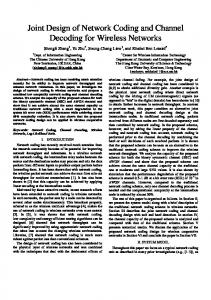
Figure 1: Sample nesC source code.
methods. Figure 1a shows a TinyOS program called SenseToLeds that displays the value of a photosensor in binary on the LEDs of a mote. SenseToLeds contains a wiring of the components Main, SenseToInt (shown in Figure 1b), IntToLeds, TimerC, and DemoSensorC. These components are just a few of the nesC components that are available in the TinyOS library. nesC interfaces can also be parameterized to provide multiple instances of the same interface in a single component. In Figure 1a, the TimerC.Timer interface is parameterized. The Timer interface of SenseToInt connects to a unique instance of the corresponding interface of TimerC. If another component connects to the TimerC.Timer interface, it will be connected to a different instance. Each timer can be initialized with different periods. In Ptolemy II, basic executable code blocks are called actors and may contain input and output ports. A port may be a simple port that allows only a single connection, or it may be a multiport that allows multiple connections. Fan-in to or fan-out from simple ports may be achieved by placing a relation in the path of the connection. A code block is stored in a class, and an actor is an instance of the class. We have developed the following representation scheme for the various parts of nesC components in Viptos. We represent nesC components with Ptolemy II classes, and nesC component interfaces with Ptolemy II ports. We represent nesC uses interfaces with Ptolemy II output ports, and nesC provides interfaces with Ptolemy II input ports. We currently represent non-parameterized interfaces with simple ports; and single-index, parameterized interfaces with multiports.1 Although multiple-index parameterized interfaces are allowed in nesC, Viptos does not support them, since they are not used in practice and do not appear in any existing components in the TinyOS component library. Figure 2c shows a graphical representation in Viptos of the equivalent wiring diagram for the SenseToLeds configuration shown in Figure 1a. Relations are represented by diamond-shaped icons. Note that in Figure 2c, the TimerC component provides a parameterized interface, or input mul1 See Section 5 for limitations of this representation and planned improvements.
tiport, as indicated by the white triangle pointing into the block. Non-parameterized interfaces, or simple ports, are represented by black triangles.
2.2
Transformation of nesC components
As the implementation for representing nesC components, Viptos uses MoML (Modeling Markup Language) [11], an XML-based language used in Ptolemy II to specify interconnections of parameterized, hierarchical components. As discussed in Section 2.1, a nesC component is either a subcomponent of an application if it exposes interface methods, or a top-level application if it does not. We treat subcomponents and top-level applications differently when transforming nesC files into MoML. For nesC subcomponents, we provide a tool called nc2moml ; for nesC top-level applications, we provide a tool called ncapp2moml. nc2moml harvests TinyOS nesC component files and converts them into Viptos MoML class files. We implemented the first version of nc2moml by modifying the nesC 1.1 compiler. The current version of nc2moml uses the XML output feature of the nesC 1.2 compiler, which decouples nc2moml from nesC compiler version updates. Both versions of nc2moml use information in the nesC XML output to generate MoML syntax that specifies the name of the component, as well as the name and input/output direction of each port, and whether they are multiports. The resulting MoML files are used in Viptos to display TinyOS components as a library of graphical blocks. The user may drag and drop components from the library onto the workspace and create connections between component interfaces by clicking and dragging between ports. Figure 3 shows generated MoML code for the TimerC component referenced in Figure 1a. Figure 2c shows a TinyOS program created using components from the converted library. ncapp2moml harvests TinyOS nesC application files and converts them into Viptos MoML model files. Whereas nc2moml only examines the nesC component interfaces, TinyOS application files in nesC do not have interfaces. ncapp2moml uses information about the nesC wiring graph and the referenced interfaces in the XML output from the nesC 1.2 compiler to generate MoML syntax that specifies a model containing the class corresponding to each nesC component used, the relations required at each port, and the links between the ports and relations such that the connections in the model correspond to the connections between interfaces in the nesC file. ncapp2moml can also automatically embed the converted TinyOS application into a template model containing a representation of the hardware interface of the node and optionally, a default physical environment. Figure 4 shows an example of a portion of the MoML code generated from the file shown in Figure 1a. For both nc2moml and ncapp2moml, we use the NDReader Java class provided in the nesC compiler distribution to parse nesC XML output and place it in nesC-specific data structures. We use JDOM 1.0 to construct and generate XML output. We choose not to use XSLT (Extensible Stylesheet Language Transformations) because of the simplicity of the Viptos MoML files.
Figure 3: Generated MoML for TimerC.nc
... ... ... ... ...
Figure 4: Generated MoML for SenseToLeds.nc
2.3
Generation of code for target deployment
When a user compiles a TinyOS program for a sensor node, the nesC compiler automatically searches the TinyOS component library paths for included components, including
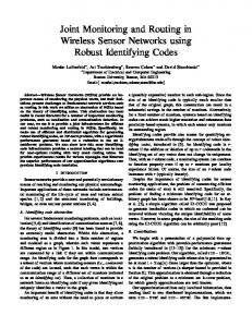
directories containing the components that encapsulate the hardware components specific to the target platform, such as the clock, radio, and sensors. The nesC compiler generates a pre-processed C file, which can then be sent to a cross compiler for the target hardware. Given a model of a TinyOS program (as in Figure 2c), Viptos will transform the diagram into a nesC file. Note that this is the opposite of ncapp2moml, which means that it is possible to convert back and forth between Viptos models and nesC files. Viptos does this transformation by means of a Director (called PtinyOS Director), which controls code generation, simulation, and deployment to target hardware for a single node. a user can configure the PtinyOS Di-
rector (Figure 2d) to compile the generated nesC code to any target supported by the TinyOS make system, including cross-compilation to target hardware, or TOSSIM for external simulation. The user can also download code to the target hardware from the Viptos interface. Running the model in Figure 2c causes the PtinyOS Director to generate a nesC component file for SenseToLeds, equivalent to that shown in Figure 1a, as well as a makefile.
2.4
Generation of code for simulation
For TOSSIM, the nesC compiler follows the procedure described in Section 2.3, but replaces the TinyOS scheduler and device drivers with TOSSIM code. Thus, the TOSSIM
a
e
b
c
f
d
Figure 2: SenseToLeds application in Viptos.
executable image depends on the particular TinyOS program specified. Viptos can also be used as a simulation environment, which provides more capabilities than using TOSSIM alone. In addition to simulating the wireless sensor node(s) running TinyOS, Viptos users can model and simulate the physical environment, radio channels, wired subsystems, and other wireless nodes, including non-TinyOS nodes. The user can take advantage of the hierarchical, heterogeneous nature of Ptolemy II to create detailed models of physical phenomena such as light, temperature, and sound; and models of entities such as buildings, servers, microservers, and other nodes. Developers may choose from diverse models of computation, such as continuous-time, dataflow, synchronous/reactive, time-triggered, and Kahn process networks. Users may also interface to live data through Ptolemy II library blocks such as those that interface with the microphone or the IP network. A basic example with models of a sensor node and a light source is shown in Figure 2a. As a template for modeling a real wireless sensor node, Viptos provides a model of the Mica mote hardware interface. The hardware representation includes ports for the ADC (analog-to-digital converter) channels connected to sensors including a thermistor, photoresistor, microphone, magnetometer, and accelerometer; and ports for the LEDs and radio communication. Figure 2b shows this graphically. Running the model in Figure 2b causes the PtinyOS Director to generate a nesC file and a makefile. It then compiles the nesC file against a custom version of TOSSIM to create a shared library. The PtinyOS Director also generates a Java wrapper to load the shared library into Viptos so that it can be run via JNI (Java Native Interface) method calls, which is used to allow calls to be made between the C-based TOSSIM environment and the Java-based Ptolemy II environment.
2.5
Simulation of TinyOS in Viptos
In this section, we explain how Viptos simulates TinyOS programs. We discuss the integration of the TOSSIM and Ptolemy II framework in terms of scheduling, type system, radio and I/O, and support for multiple nodes and multihop routing.
2.5.1
Scheduling
In TinyOS, there is a single thread of control managed by the scheduler, which may be interrupted by hardware events. nesC component methods encapsulate hardware interrupt handlers. Methods may transfer the flow of control to another component by calling a uses method. Computation performed in a sequence of method calls must be short, or it may block the processing of other events. A long running computation can be encapsulated in a task, which a method posts to the scheduler task queue. The TinyOS scheduler processes the tasks in the queue in FIFO order whenever it is not executing an interrupt handler. Tasks are atomic with respect to other tasks and do not preempt other tasks. TOSSIM is a discrete event simulator for TinyOS. Its scheduler contains a task queue similar to the regular TinyOS scheduler, as well as an ordered event queue. An event in this queue has a time stamp implemented as a long long in C (a 64-bit integer on most systems). The smallest time resolution is equal to 1 / 4MHz, the original CPU frequency of the Rene/Mica motes.
Upon initialization, TOSSIM inserts a boot up event into the event queue. The TOSSIM scheduler begins its main loop by processing all tasks in the task queue in FIFO order. If there is an event in the event queue, it updates the simulated system time with the time stamp of the new event and then processes the event. The processing of an event may cause tasks to be posted to the task queue and new events to be created with time stamps possibly equal to the current time stamp. In TOSSIM, all components call the queue_insert_event() function to insert new events into the event queue. At the top level of a model, Viptos uses a specialization of the discrete-event (DE) domain of Ptolemy II [2] created for modeling of wireless systems in VisualSense. The DE domain provides execution semantics where interactions between components occur via events with time stamps. A sophisticated calendar-queue scheduler is used to efficiently process events in chronological order. The DE domain has a formal semantics that ensures determinate execution of deterministic models [10], although stochastic models for Monte Carlo simulation are also well supported. The precision in the semantics prevents the unexpected behavior that sometimes occurs due to modeling idiosyncrasies in some modeling frameworks. In Viptos, the specialized DE Director may control one or more node models. In Viptos, a node model contains an instance of PtinyOS Director, which compiles and loads a custom copy of TOSSIM that simulates the code for a single node. Viptos controls the execution of TOSSIM by instrumenting the TOSSIM scheduler and device driver functions to notify Viptos of all TOSSIM events. Viptos modifies the TOSSIM queue_insert_event() function so that it also makes a JNI call to insert an event with the TOSSIM time stamp into the event queue of the Ptolemy II discrete event scheduler (DE Director) that controls the PtinyOS Director. Thus Viptos uses the same event time stamps as TOSSIM. At each event time stamp, Viptos calls the custom TOSSIM scheduler to process the event. The main loop updates the TOSSIM system time, processes an event in the TOSSIM event queue, and then processes all tasks in the task queue. If the TOSSIM event queue contains another event with the current TOSSIM system time, the scheduler processes the event along with any tasks that may have been generated. This last step is repeated until there are no other events with the current TOSSIM system time. Note that the order in the main loop of the custom TOSSIM scheduler is opposite that of the original TOSSIM, which processes all tasks before updating the TOSSIM system time and processing an event in the TOSSIM event queue. This change is required in order to guarantee causal execution in Viptos, since tasks may generate events with the current TOSSIM time stamp. Otherwise, new events may have a time stamp that is before the current Ptolemy II system time. Viptos supports models with dynamically changing interconnection topologies. Changes in connectivity are treated as mutations of the model structure. The software is carefully architected to support multithreaded access to this mutation capability. Thus, one thread can be executing a simulation of the model while another changes the structure of the model, for example by adding, deleting, or moving actors, or changing the connectivity between actors. The results are predictable and consistent.
2.5.2
Type system
nesC components in TinyOS and TOSSIM use the type system provided by C. Ptolemy II provides its own type system, in which actors, parameters, and ports may all impose constraints on types, and a type resolution algorithm identifies the most specific types that satisfy all the constraints. Communication between actors in Ptolemy II occurs through typed tokens. Several techniques were required to compose the C type system and the Ptolemy II type system for Viptos. To facilitate the embedding of a different type system within Ptolemy II, we created a special Java base class (called TypeOpaqueCompositeActor ) that allows a Ptolemy II actor’s ports to have types, but does not require that the actors inside use the Ptolemy II type system. A Viptos submodel containing nesC components uses a subclass of this base class (called PtinyOSCompositeActor ), so that the components can use the C type system. Viptos automatically converts between the C types used in TOSSIM and the token types used in Ptolemy II, by means of JNI functions in the custom copy of TOSSIM. Since the data communicated between TOSSIM and Ptolemy II involve only the mote’s hardware interface, we can limit type conversion to the data types required by the ADC interface, the LEDs, and the packets sent and received over the radio. However, the types provided by C usually do not match the actual data types of the hardware interface. As a result, arbitrary data types are used in TinyOS and TOSSIM to represent values with different bit widths, which we explain next. The ADC channels of a mote use 10-bit unsigned values. TOSSIM represents an ADC value with an unsigned short integer masked for 10-bit usage. Sensor data modeled in Ptolemy II typically use tokens with values of type double. When an ADC value is requested by TOSSIM, Viptos automatically performs the lossy conversion from a doublevalued token in Ptolemy II to a masked unsigned short integer value in TOSSIM. Although LED state is binary, TOSSIM represents an LED value with a char. When TOSSIM updates the state of the LEDs, Viptos automatically converts the char in TOSSIM into a boolean-valued token in Ptolemy II, which is used to change the animation state of the LEDs in Viptos. In TOSSIM, TinyOS packets are represented by a C data structure containing a char array. In order to maintain a standard endian format and enable easy parsing of packets, Viptos represents TinyOS packets using Ptolemy II string tokens. Viptos automatically converts between the TOSSIM char array representation and the Ptolemy II string token representation whenever a packet is transmitted or received.
2.5.3
Radio and I/O
TOSSIM has built-in models for per-node ADC values and for radio connectivity between multiple nodes, as well as an interface for manually setting the per-node and perlink values and probabilities. In Viptos and VisualSense, the algorithm for determining radio connectivity is itself encapsulated in a component as a channel model, and hence can be developed by the model builder. Both tools provide several built-in models, including AtomicWirelessChannel, DelayChannel, LimitedRangeChannel, ErasureChannel, and PowerLossChannel (see the left-hand pane of Figure 2a. Connectivity can be
determined on the basis of the physical locations of the components. Viptos overrides the built-in ADC and radio models and LED device drivers in TOSSIM so that they send data to and receive data from the ports of the node model. This allows the simulated node to interact with user-created models of sources of light (see Figures 2e and 2f), temperature, radio channels, other nodes, etc. In the DE domain of Ptolemy II, tokens received at the input port of an actor will cause the actor to fire at the time of the token time stamp. The token is usually consumed, at which point the port is empty. In Viptos, the node model may receive tokens on the ADC ports that represent new values. To reconcile the difference in timing between when the simulated environment makes a new ADC value available and when the simulated node reads its ADC ports, Viptos uses a Ptolemy II PortParameter instead of a Port for the ADC ports. This usage of the PortParameter makes the port value persistent between updates such that when the TinyOS program requests data from the ADC port, it gets the value of the most recently received token. Figure 2a shows an example of a node running the SenseToLeds TinyOS program with a model of a light source. Light source data is communicated to the sensor node by means of a photo port associated with a LimitedRangeChannel.
2.5.4
Multiple nodes and multihop routing
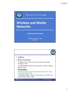
TOSSIM allows one or more nodes with the same TinyOS program to be simulated by maintaining a copy of the state of each component for each simulated node. Support for generating arrays to store these copies is built into the nesC compiler, so that users do not need to modify the TinyOS program source code. In Viptos, multiple nodes with possibly different programs are simulated simultaneously by embedding multiple node models, with each TinyOS node containing a different PtinyOS Director, into the Wireless domain. Viptos separately compiles and loads a shared library for each node to prevent namespace collision between different simulated TinyOS programs. Viptos performs this by passing a unique name to the nesC compiler, which is then inserted by means of macros into the TOSSIM source code. Since there is a global discrete event scheduler, all nodes operate on the same time reference. Figure 5 shows an example model that contains two nodes that communicate over a lossless radio channel with full connectivity. The first node contains the CntToLedsAndRfm TinyOS program, which maintains a counter on a 4Hz timer, displays the counter value on the LEDs, and sends it over the radio in a TinyOS packet. The second node contains the RfmToLeds TinyOS program, which listens for radio packets and displays the received values on the LEDs. The radio channel model can easily be replaced by deleting it and dragging in a different channel model from the menu in the left-hand pane. Though the application shown in Figure 5 uses broadcast, we have also developed support for multihop routing in Viptos. We accomplish this by passing a unique node ID to the nesC compiler for each custom copy of TOSSIM. We modify the TOSSIM code to use this node ID where it would normally be used in TinyOS, instead of the default TOSSIM node index value. We allow users to indicate whether a node is a base sta-
tion in the PtinyOS Director configuration screen (this new feature is not shown in the figure). This gives users the ability to model multiple sinks in the wireless sensor network. We have implemented a multihop routing demonstration in Viptos that models a network with multiple TinyOS nodes running the Surge multihop routing protocol application.
3.
PERFORMANCE EVALUATION
We evaluate the scalability of Viptos in terms of execution time for an increasing number of nodes. We evaluate execution time with and without radio usage separately. Timing information was collected on a Intel Pentium M 760 processor (2.0GHz, 2MB L2 Cache, 533MHz FSB) with 1024MB of SDRAM, running Ubuntu 6.06 LTS (Dapper Drake) with Linux kernel 2.6.15-27-386. We use nesC 1.2.7a, gcc 3.4.3, TinyOS 1.x, and Sun Java VM 1.4.2 13-b06 with a heap size of 512MB. In order to run large models, we increase the maximum number of open file descriptors allowed in the Bash shell from 1024 to 20000 with the ulimit -n command. To eliminate timing variance due to random boot times, we set all nodes to boot at virtual time 0.0 seconds. We do not set the DBG environment variable, which affects which event debug messages are generated in TOSSIM. We send all printed debug messages (on stdout or stderr) from all copies of TOSSIM to /dev/null, to eliminate timing variance from printing to the screen under X11.
3.1
Comparison to TOSSIM
We use the SenseToLeds application to evaluate the scalability of Viptos and compare it to TOSSIM. For TOSSIM, we use the /usr/bin/time command to measure the execution time of the SenseToLeds application from the tinyos-1.x CVS tree. We discard the timing measurement for the first run to eliminate timing variance due to caching. For Viptos, we instrument the PtinyOS Director with calls to the Java Date().getTime() and Runtime.getRuntime()
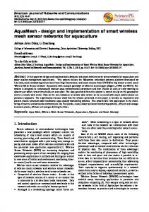
methods to measure elapsed time when running the SenseToLeds application displayed in Figure 2. We eliminate the model of the environment in order to make a fair comparison to TOSSIM, since TOSSIM uses random ADC values by default. For models with multiple nodes, we use the timing information from the last node to start, since nodes must wait until all internal copies of TOSSIM have been invoked before simulation can proceed because they all operate on the same time reference. For a given number of nodes, we collect multiple runs from the same instantiation of Viptos. We discard the timing measurement for the first run in order to eliminate timing delay due to loading of new Java classes, instantiation of Java objects, and caching. To model additional nodes, we copy and paste additional nodes into the graph, save the model, restart Viptos, and take additional measurements. In order to measure the overhead due to integrating TOSSIM with Ptolemy II, we start timing right before invoking the internal copy of TOSSIM. We do not include the overhead of running the nesC compiler and loading the TOSSIM shared object into memory. We stop timing at the beginning of wrapup(), in order to eliminate timing delay due to waiting for remaining threads to join, since this is only necessary for running the model multiple times within a graphical environment. To reduce timing variance due to Java garbage collection, we call System.gc() to perform garbage collection before starting the timing measurement. We do not present timing overhead in Viptos for opening files; running the nesC, gcc, and Java compilers; or loading shared objects. This overhead scales linearly with the number of nodes, and is on the order of a few seconds for small models, and several minutes for large models. Figure 6 shows the average execution time of the SenseToLeds application with a virtual run time of 300.0 seconds for an increasing number of nodes. The figure shows that Viptos has more overhead when compared to TOSSIM, but both simulators scale linearly in the number of nodes. We conclude that in exchange for slightly increased execution time,
Figure 5: SendAndReceive application in Viptos.
Figure 6: Execution time of the SenseToLeds application as a function of the number of nodes. Each simulation ran for 300.0 virtual seconds. the user gains increased modeling and simulation capabilities and flexibility, and an interactive, graphical programming environment. Using a least squares linear regression, we find that approximately 410 nodes can be simulated in 300.0 real seconds or less, which means that networks up to this size can be simulated in real-time. The exact number depends on the fidelity of simulation required and the complexity of the application.
3.2
Radio
We evaluate the scalability of models that use the radio using the same techniques described above. We create a model similar to that of Figure 5 (described in Section 2.5.4) with a lossless radio channel model with full connectivity, but with a varying number of senders and receivers. Senders send packets at 4 Hz. To eliminate timing variance due to the graphical interface, we disable animation of the LEDs in Viptos. In this analysis, we use a virtual run time of 120.0 seconds for all nodes. From the plot shown in Figure 7, the main determinant of execution time is the total number of nodes. The number of senders versus receivers has no noticeable effect. We conclude that the execution time of the model increases linearly with the number of nodes, whether or not the radio is used.
4.
RELATED WORK
A number of frameworks for modeling wireless systems exist, though none include all of the capabilities of Viptos. ns-2 is a well-established, open-source network simulator. It is a discrete event simulator with extensive support for simulating TCP/IP, routing, and multicast protocols over wired and wireless (local and satellite) networks. Wireless and mobility support in ns-2 comes from the Monarch project, which provides channel models and wireless network layer components in the physical, link, and routing layers. OPNET Modeler is a commercial tool that offers sophisticated modeling and simulation of communication networks. An OPNET model is hierarchical, where the top level is a discrete event simulation and nodes can be constructed using finite state machine (FSM) models. The OPNET Wireless Module provides support for wireless and mobile communi-
Figure 7: Execution time of a radio send and receive model in Viptos as a function of the number of senders and receivers. Each simulation ran for 120.0 virtual seconds.
cations. OMNET++ [16] is an open source tool for discrete-event modeling. With the Mobility Framework extension, it shares many concepts, solutions and features with OPNET. But instead of using FSM models for processes, it defines a component interface for the basic module, with an object-oriented approach similar to the abstract semantics of Ptolemy II [3]. The NesCT tool of the EYES WSN project allows users to run TinyOS applications directly in OMNeT++ simulations. J-Sim [15] is an open-source, component-based, compositional network simulation environment that is developed entirely in Java. A new wireless sensor framework [14] is being developed that provides an object-oriented definition of (i) target, sensor and sink nodes, (ii) sensor and wireless communication channels, and (iii) physical media such as seismic channels, mobility model and power model (both energy-producing and energy-consuming components). Prowler [13] is a probabilistic wireless network simulator running under MATLAB capable of simulating wireless distributed systems, from the application to the physical communication layer. Prowler is an event-driven simulator that can be set to operate in either deterministic mode (to produce replicable results while testing the application) or in probabilistic mode that simulates the nondeterministic nature of the communication channel and the low-level communication protocol of the motes. Em* [6] is toolsuite for developing sensor network applications on Linux-based hardware platforms called microservers. It supports deployment, simulation, emulation, and visualization of live systems, both real and simulated. EmTOS [7] is an extension to Em* that enables an entire nesC/TinyOS application to run as a single module in an Em* system. TinyViz [12] is a Java-based graphical user interface for TOSSIM. TinyViz supports software plugins that watch for events coming from the simulation – such as debug messages, radio messages, and so forth – and react by drawing information on the display, setting simulation parameters,
or actuating the simulation itself, for example, by setting the sensor values that simulated motes will read. All of these systems provide extension points where modelbuilders can define functionality by adding code. Some are also open-source software, like Viptos. None provide the ability to transition from high-level modeling to real code simulation and deployment. All except EmStar provide some form of discrete-event simulation, but none provide the ability that Viptos inherits from Ptolemy II to integrate diverse models of computation, such as continuous-time, dataflow, synchronous/reactive, and time-triggered. This capability can be used, for example, to model the physical environment, as well as the physical dynamics of mobility of sensor nodes, their digital circuits, energy consumption and production, signal processing, or real-time software behavior. Such models would have to be built with low-level code. Viptos and Ptolemy II support hierarchical nesting of heterogeneous models of computation [3]. It also appears to be unique among these modeling environments in that FSM models can be arbitrarily nested with other models; i.e., they are not restricted to be leaf nodes [5]. It also appears to be the only one to provide a modern type system at the actor level (vs. the code level) [17].
5.
DISCUSSION AND FUTURE WORK
We faced a number of design choices and implementation issues when creating Viptos. Viptos currently compiles and loads a separate copy of TOSSIM for each node, and loads a new copy for each run, even if the model has not changed. This was done to minimize changes to TOSSIM. To reuse an existing copy of TOSSIM, all of its variables must be returned to their initial states after a run has completed, which TOSSIM does not do. It was not feasible to track down all of these variables. An area of improvement for scalability would be to condense similar programs into the same copy of TOSSIM, and to reuse previously loaded copies of TOSSIM. A running copy of TOSSIM opens two TCP network sockets to communicate with external tools like TinyViz [12]. We chose not to use this feature to connect TOSSIM to Ptolemy II, since we wanted full control of the TOSSIM scheduler, which would not have been possible with the network message interface provided by TOSSIM. However, we retained these network sockets for backwards compatibility with TinyViz. In retrospect, it would have been better to eliminate usage of the network sockets entirely, since they caused major implementation problems when porting Viptos from Linux to Cygwin on Windows. Viptos contained many types of threads, including pthreads used by TOSSIM to manage the network sockets, and Java threads used by Ptolemy II to manage the graphical user interface. When porting to Cygwin, we found that there were both thread library problems and thread deadlock problems due to the underlying implementation of Cygwin on Windows. To circumvent these problems, we replaced all of the pthread and POSIX socket library usages in TOSSIM with their equivalents in Java, and we created a C-based launcher program that starts the Viptos Java process under Cygwin. An interesting area of future work is TinyOS 2.0, which was released in November 2006. The TinyOS 2.0 scheduler has slightly different, but improved semantics compared to the TinyOS 1.x scheduler. The TinyOS 2.0 library was written from scratch, with the explicit goal of cleaning up prob-
lems and inconsistencies in the TinyOS 1.x library. Also, TOSSIM in TinyOS 2.0 does not use pthreads or sockets. These features make TinyOS 2.0 an ideal platform for a future version of Viptos. Other interesting topics include how to enable code dissemination algorithms such as Deluge [9]; and distributed compilation, simulation, and execution. We are also investigating how to represent the individual methods of an interface using ports or an alternate visual syntax. We describe reasons for this change in the next section.
5.1
Ports
The current mapping of non-parameterized nesC interfaces to Ptolemy II simple ports and parameterized nesC interfaces to Ptolemy II multiports leads to an inability to express certain types of nesC configurations. For example, suppose a configuration contains the following wiring, where a, b, c, and d are non-parameterized interfaces: a -> d b -> d a -> c Then, the original Viptos mapping will produce an extra connection between b and c, since in Ptolemy II, relations are required to create multiple connections to port d, and relations that are connected to each other are considered to be part of a relation group in which the relations are indistinguishable from each other, and connections between relations are directionless. Similarly, multiple connections between the same uses and provides interfaces may be lost or lead to extra connections when translating from nesC to MoML. Since relations in a group are indistinguishable from each other, multiple connections between relations cannot be represented in Ptolemy II. We plan to change the current multiport/simple port distinction and represent both parameterized and non-parameterized nesC interfaces with multiports. We plan to attach a Ptolemy II parameter to multiports that represent parameterized nesC interfaces. The value of the parameter will be an array of integers that is constrained to have a length equal to the number of connections made to the port. Using multiports for all connections will allow all types of connections that can be made in nesC. Note that multiple connections to the same provides port may actually be a sign of a possible race condition, since the provided code can be triggered by simultaneous events from the physical world. However, to avoid duplicate functionality, we rely on the nesC compiler to do a complete analysis of the connected interface methods to detect incorrect usage of commands or events marked with the async keyword and hence possible race conditions.
6.
CONCLUSION
We have described an extensible software framework for modeling sensor networks. This tool, called Viptos, is built upon Ptolemy II and TinyOS, and provides an integrated graphical design and simulation environment. It allows users to easily transition from high-level, hierarchical, heterogeneous modeling to low-level implementation, simulation, and deployment. We showed that Viptos simulator performance is scalable, and execution time scales linearly as a function of the number of nodes, and even without aggressive per-
formance tuning, can simulate moderately large sensor networks effectively. Viptos is open-source software, freely available at http: //ptolemy.eecs.berkeley.edu/viptos. We hope that the community can use this framework to encapsulate and exchange methods and expertise in channel modeling, sensor node design, and application development.
Acknowledgments This work was supported in part by the Center for Hybrid and Embedded Software Systems (CHESS) at UC Berkeley, which receives support from the National Science Foundation (NSF award #CCR-0225610), the State of California Micro Program, and the following companies: Agilent, DGIST, General Motors, Hewlett Packard, Infineon, Microsoft, National Instruments, and Toyota. The authors would like to thank Christopher Brooks for Viptos release management, David Gay for the nesC 1.2 XML output feature and associated Java tools, Jie Liu for helpful feedback, Heather Taylor for work on Surge, and Andrew Mihal and Erik Steltz for assistance with the performance analysis.
7.
REFERENCES
[1] P. Baldwin, S. Kohli, E. A. Lee, X. Liu, and Y. Zhao. Modeling of sensor nets in Ptolemy II. In IPSN’04: Proceedings of the Third International Aymposium on Information Processing in Sensor Networks, pages 359–368, New York, NY, USA, 2004. ACM Press. [2] C. Brooks, E. A. Lee, X. Liu, S. Neuendorffer, Y. Zhao, and H. Z. (eds.). Heterogeneous concurrent modeling and design in Java: Volume 3: Ptolemy II domains. Technical Report Technical Memorandum UCB/ERL M05/23, University of California, Berkeley, July 15 2005. [3] J. Eker, J. W. Janneck, E. A. Lee, J. Liu, X. Liu, J. Ludvig, S. Neuendorffer, S. Sachs, and Y. Xiong. Taming heterogeneity – the Ptolemy approach. Proceedings of the IEEE, Special Issue on Modeling and Design of Embedded Software, 91(1):127–144, January 2003. [4] D. Gay, P. Levis, R. von Behren, M. Welsh, E. Brewer, and D. Culler. The nesC language: A holistic approach to networked embedded systems. In Proceedings of Programming Language Design and Implementation (PLDI) 2003, June 2003. [5] A. Girault, B. Lee, and E. A. Lee. Hierarchical finite state machines with multiple concurrency models. IEEE Transactions On Computer-Aided Design Of Integrated Circuits and Systems, 18(6), June 1999. [6] L. Girod, J. Elson, A. Cerpa, T. Stathopoulos, N. Ramanathan, and D. Estrin. EmStar: A software environment for developing and deploying wireless sensor networks. In USENIX 2004 Annual Technical Conference, pages 283–296, 2004. [7] L. Girod, T. Stathopoulos, N. Ramanathan, J. Elson, D. Estrin, E. Osterweil, and T. Schoellhammer. A system for simulation, emulation, and deployment of heterogeneous sensor networks. In Proceedings of the 2nd International Conference on Embedded Networked Sensor Systems, pages 201–213. ACM Press, 2004.
[8] J. Hill, R. Szewczyk, A. Woo, S. Hollar, D. Culler, and K. Pister. System architecture directions for networked sensors. In Proceedings of the Ninth International Conference on Architectural Support for Programming Languages and Operating Systems, pages 93–104. ACM Press, 2000. [9] J. W. Hui and D. Culler. The dynamic behavior of a data dissemination protocol for network programming at scale. In Proceedings of the 2nd international conference on Embedded networked sensor systems, pages 81–94. ACM Press, 2004. [10] E. A. Lee. Modeling concurrent real-time processes using discrete events. Ann. Softw. Eng., 7(1-4):25–45, 1999. [11] E. A. Lee and S. Neuendorffer. MoML – a modeling markup language in XML – version 0.4. Technical report, University of California at Berkeley, March 2000. [12] P. Levis, N. Lee, M. Welsh, and D. Culler. TOSSIM: accurate and scalable simulation of entire tinyos applications. In Proceedings of the 1st International Conference on Embedded Networked Sensor Systems (SenSys 2003), pages 126–137. ACM Press, 2003. ´ [13] G. Simon, P. V¨ olgyesi, M. Mar´ oti, and Akos L´edeczi. Simulation-based optimization of communication protocols for large-scale wireless sensor networks. In Proceedings 2003 IEEE Aerospace Conference, volume 3, pages 3 1339–3 1346, 2003. See also http://www.isis.vanderbilt.edu/projects/nest/prowler/. [14] A. Sobeih, W.-P. Chen, J. C. Hou, L.-C. Kung, N. Li, H. Lim, H.-Y. Tyan, and H. Zhang. J-Sim: A simulation and emulation environment for wireless sensor networks. online, 2005. http://www.j-sim.org/v1.3/sensor/JSim.pdf. [15] H.-Y. Tyan. Design, realization and evaluation of a component-based compositional software architecture for network simulation. PhD thesis, 2002. See also http://www.j-sim.org. [16] A. Varga. The OMNeT++ discrete event simulation system. In Proceedings of the European Simulation Multiconference (ESM’2001), Prague, Czech Republic, June 6-9 2001. http://www.omnetpp.org/. [17] Y. Xiong. An extensible type system for component-based design. Technical Report UCB/ERL M02/13, EECS Department, University of California, Berkeley, 2002.