Oct 29, 2008 - jointly calculate the CQI and the PCI in order to maximize the data throughput. .... canceled by a decision feedback equalizer [15], whereas the stochastic ..... [Online]. Available: http://publik.tuwien.ac.at/files/pub-et 10929.pdf.
Copyright 2001 SS&C. Published in the Conference Record of the Fourtysecond Asilomar Conference on Signals, Systems and Computers, 2008, October 26-29, 2008, Pacific Grove, CA, USA.
Joint Throughput Optimized CQI and Precoding Weight Calculation for MIMO HSDPA Christian Mehlf¨uhrer, Sebastian Caban, Martin Wrulich, and Markus Rupp Institute of Communications and Radio-Frequency Engineering Vienna University of Technology Gusshausstrasse 25/389, A-1040 Vienna, Austria Email: {chmehl, scaban, mwrulich, mrupp}@nt.tuwien.ac.at Web: http://www.nt.tuwien.ac.at/rapid-prototyping
Abstract—In MIMO High Speed Downlink Packet Access, the channel adaptation is performed by means of the Channel Quality Indicator (CQI) and the Precoding Control Indicator (PCI). The CQI value is utilized to determine the coding rate and modulation alphabet, as well as the number of spatially multiplexed data streams. The PCI value is associated to a specific precoding vector that is applied to the transmit signal at the basestation. In this work, we derive analytic expressions for the post equalization SINR. These SINR values are then evaluated at the receiver to jointly calculate the CQI and the PCI in order to maximize the data throughput. The SINR expressions are verified not only by simulations but also by outdoor MIMO HSDPA measurements.
I. I NTRODUCTION In 2007, 3GPP standardized Dual Stream Transmit Antenna Array (D-TxAA) as the 2×2 MIMO extension for High Speed Downlink Packet Access (HSDPA) [1, 2]. D-TxAA uses precoding at the transmitter and can be operated in single or dual stream mode depending on the channel conditions. Like in SISO HSDPA, the Transport Block Size (TBS), that is, the number of data bits to be transmitted in one data stream per subframe, is adjusted using Channel Quality Indicator (CQI) signaled by the user. In SISO HSDPA, the user equipment can calculate the CQI value by blindly estimating the post equalization Signal to Interference and Noise Ratio (SINR) at the demapper input (that is after equalization, descrambling, and despreading). Using a lookup table, the post equalization SINR is mapped to a CQI value that allows for a transmission with a BLER smaller than 10% [1, 3]. The required mapping tables or mapping functions are obtained by AWGN Block Error Ratio (BLER) simulations. In MIMO HSDPA, the user equipment has to signal, additionally to the CQI value, a so-called Precoding Control Indicator (PCI) that determines a precoding vector. The precoding vector is then applied to the user’s downlink chip stream to form the transmit signals of the two transmit antennas. In flat fading channels, the 2×1 Transmit Antenna Array (TxAA) system could achieve the same diversity [4] and array gain as a 1×2 system if the precoding would not be quantized. Nevertheless, due to the quantized precoding and the frequency selectivity of the wireless channel, some performance loss is
immanent. Note that TxAA was already standardized for SISO HSDPA but was never applied widely in mobile networks. Related Work The HSDPA specification [1] proposes a method for evaluating the channel dependent feedback based on the channel knowledge at the receiver. This method separates the problem of CQI and PCI calculation by first selecting a precoding vector in order to maximize the received pre-equalization Signal to Noise Ratio (SNR) [5, 6]. The appropriate CQI value is selected by observing the post equalization SINR. Although this method is of low complexity, it has two drawbacks: 1) It does not provide a decision if single stream or dual stream transmission shall be used. 2) Assume that the user equipment receives an HSDPA subframe at time t=1. Then the user equipment determines the PCIt=1 from the estimated channel coefficients. In the same subframe, the user equipment also determines the CQIt=1 from the current post equalization SINR although the received subframe was weighted by the previously signaled precoding PCIt=0 . In case the precoding information often changes over time, the CQI will be underestimated (since the new, updated precoding vector usually will lead to larger SINR) and consequently the data throughput will reduce. Contribution First, we derive analytic expressions for the post equalization SINR of MIMO HSDPA receivers. More specifically, these SINR expressions cover arbitrary equalizers, interference cancelation schemes, and channel estimation effects. We furthermore utilize the SINR expressions to jointly determine the precoding vector, the supported TBS, and the number of streams. For doing this, we need to evaluate the post equalization SINRs for every1 possible precoding vector. The post equalization SINRs are then mapped to CQI values using an SINR-to-CQI mapping table. The throughput optimized precoding vector is then obtained by maximizing the total transport block size2 associated to the evaluated CQI values. 1 In D-TxAA four precoding vectors are standardized in the single stream mode and two precoding vectors in the dual stream mode. 2 Note that in the dual stream mode the total TBS is given by the sum of the TBSs of the two individual streams.
Copyright 2001 SS&C. Published in the Conference Record of the Fourtysecond Asilomar Conference on Signals, Systems and Computers, 2008, October 26-29, 2008, Pacific Grove, CA, USA.
We implemented our method in a physical layer link level simulator and performed outdoor-to-indoor measurements with our testbed [7]. Besides the feedback calculation, the derived SINR expressions can also be used in system simulations to model the physical layer [8, 9]. Since we validate the SINR expressions not only by physical layer HSDPA simulations but also by outdoor measurements, these expressions are very well suited to obtain accurate system simulation results and thus realistic network performance estimates. II. S YSTEM M ODEL In this section, we present the mathematical description of the HSDPA system required to derive analytical expressions for the post equalization SINRs. A block diagram of this system description is shown in Fig. 1. Assume that we are transmitting Ns independently coded and modulated data chip streams, each of length Lc = Lh + Lf − 1 chips, Lh and Lf corresponding to the channel and the equalizer length, respectively. We define the stacked transmit chip vector as h iT (1)T (N )T sk = sk , . . . , sk s . (1) The Ns chip streams are weighted by the NT ×Ns dimensional precoding matrix w(1,1) . . . w(1,Ns ) .. .. .. W= (2) . . . w(NT ,1)
...
w(NT ,Ns )
forming the data chip streams of the NT transmit antennas. At each transmit antenna, pilot, synchronization, and control channels accumulated in h iT (1)T (N )T pk = pk , . . . , pk T (3) are added. With the Lc ×Lc dimensional identity matrix ILc , the transmit signal is given by ak = (W ⊗ ILc ) sk + pk .
(4)
The frequency selective link between the nt -th transmit and the nr -th receive antenna is modeled by the Lf ×Lc dimensional band matrix (n ,n ) (n ,n ) 0 h0 r t ... hLhr−1t .. .. , (5) H(nr ,nt ) = . . (nr ,nt ) (nr ,nt ) 0 h0 ... hLh −1 (n ,n )
where the hi r t (i = 0, . . . , Lh − 1) represent the channel impulse response between the nt -th transmit and the nr -th receive antenna. The entire frequency selective MIMO channel is modeled by a block matrix H consisting of NR ×NT band matrices defined in (5) H(1,1) . . . H(1,NT ) .. .. .. H= (6) . . . . H(NR ,1)
...
H(NR ,NT )
Fig. 1. Generalized system model for describing the HSDPA physical layer.
At the receiver, noise and out-of-cell interference, their sum denoted by vk , deteriorates the desired signal bk = Hak + vk = H (W ⊗ ILc ) sk + Hpk + vk .
(7)
The signal bk is then processed in an MMSE based [10, 11] or an interference aware [12, 13] equalizer F to obtain an estimate of the transmitted chip stream h iT (1) (N ) ˆ sk = sˆk−τ , . . . , sˆk−τs = Fbk = FH (W ⊗ ILc ) sk + FHpk + Fvk .
(8)
The equalizer matrix F here consists of Ns vectors, each of length NR Lf h iT F = f (1) , . . . , f (Ns ) . (9) III. P OST E QUALIZATION SINR C ALCULATION In this section, we derive analytic expressions for the post equalization interference terms. These expressions can be used to determine the total post equalization SINR required for calculating the CQI and PCI feedback information. Since the true channel matrix H is unknown at the receiver and can only be estimated with a certain Mean Square Error (MSE), we approximate the true channel matrix by the estiˆ and a matrix H∆ representing the mated channel matrix H channel estimation error [14]. The matrix H∆ is constructed like the channel matrix H in (5) and (6). The non-zero elements of H∆ are assumed to be i.i.d. Gaussian with a variance equal to the MSE of the channel estimator. A. HS-PDSCH Interference The High Speed Physical Downlink Shared Channel (HSPDSCH) consists of the data chip streams in sk . These code division multiplexed data chip streams generate interference due to non perfect equalization at the receiver. The total impulse response seen by all data chip streams in sk to the output of the ns -th equalization filter is given by � � ˆ + H∆ (W ⊗ ILc ) . gs(ns )T = f (ns )T H (10) The interference power at the output of the equalizer can be ˆ and a stochastic divided into a deterministic part (caused by H) part (caused by H∆ ). The deterministic interference can be canceled by a decision feedback equalizer [15], whereas the stochastic interference can only be decreased by reducing the MSE of the channel estimator. The deterministic HS-PDSCH interference power is calculated by accumulating the energies of the total impulse
Copyright 2001 SS&C. Published in the Conference Record of the Fourtysecond Asilomar Conference on Signals, Systems and Computers, 2008, October 26-29, 2008, Pacific Grove, CA, USA.
response at delays k 6= τ . The remaining interference at delay τ (the chosen delay of the transmitted chip stream after the channel and the equalizer) is irrelevant since it is perfectly removed by the despreading operation (ns ) γs,H ˆ
Lc � � 2 PHS−PDSCH X (ns )T ˆ H (W ⊗ ILc ) . = · f Ns k k=1 k6=τ
(11) Here, PHS−PDSCH corresponds to the transmit power available for all Ns data chip streams. The operator (.)k denotes the k-th element of a vector. The stochastic HS-PDSCH interference power is obtained by building the expectation with respect to the unknown channel estimation error (n )
PHS−PDSCH · Ns L c � X � 2 (ns )T H∆ (W ⊗ ILc ) · EH∆ ≈ f k k=1 k6=τ
2 PHS−PDSCH
≈ · MSE · (Lh − 1) NT f (ns ) . (12) Ns 2
γs,Hs ∆ =
In this derivation, the last step can be verified by a careful inspection of the matrix-vector multiplications. B. Pilot Interference The total impulse response seen by the pilot channels from the transmit antennas to the output of the ns -th equalization filter is given by the NT Lc length vector � � ˆ + H∆ . gp(ns )T = f (ns )T H = f (ns )T H (13) Again, we can identify a deterministic interference (n )
s γp,H ˆ =
PCPICH · NT 2 NT X Lc � X (n )T � s ˆ · H f k+(nt −1)Lc
(14)
nt =1 k=1 k6=τ
and a stochastic interference PCPICH (n ) γp,Hs ∆ = · NT N L T X c X � � (n )T 2 s · EH∆ H∆ ≈ f k+(nt −1)Lc nt =1 k=1 k6=τ
2 PCPICH
· MSE · (Lh − 1) f (ns ) . (15) ≈ NT 2 Here, PCPICH denotes the total pilot channel power for all transmit antennas.
C. Synchronization and Control Channels Interference For the calculation of the interference emerging from the synchronization and control channels we assume that these channels are transmitted on all antennas simultaneously, that is, the power is equally distributed on all transmit antennas. Since the Synchronization Channel (SCH) and the control channel (PCCPCH) are transmitted time multiplexed, we assume that both channels have equal power; that is, PSCH = PCCPCH . The total impulse response of the synchronization and control channels to the output of the ns -th equalization filter is given by � 1 (ns )T � ˆ (ns )T H + H∆ (1NT ⊗ ILc ) . (16) f gSCH =√ NT Here, 1NT denotes an NT × 1 dimensional vector with all entries equal to one. Note that the multiplication with (1NT ⊗ ILc ) represents the summation of the individual transmit antenna impulse responses. This is required because we assumed that synchronization and control channels are equally distributed on all transmit antennas. The deterministic part of the interference is calculated as (n )
s γSCH, ˆ = H
Lc � � 2 PSCH X (ns )T ˆ · H (1NT ⊗ ILc ) f NT k
(17)
k=1 k6=τ
and the stochastic interference as PSCH (ns ) · γSCH,H = ∆ NT L c X � � 2 (ns )T ≈ H∆ (1NT ⊗ ILc ) · EH∆ f k k=1 k6=τ
2 PSCH
≈ · MSE · (Lh − 1) f (ns ) . NT 2
(18)
Additionally to the two interference terms above, interference at delay lag k = τ emerges from the SCH since it is transmitted without spreading and scrambling and is thus not orthogonal to the data channels � 2 PSCH � (ns )T ˆ (ns ) f H (1 ⊗ I γSCH, = 0.1 ) , (19) N L T c ˆ H,τ NT τ (n )
� � � 2 � PSCH EH∆ f (ns )T H∆ = NT τ PSCH =0.1 · MSE· NT 2 Lh � NR X X (n ) � f s . (20) · k+τ −Lh +(nr −1)Lf
s =0.1 γSCH,H ∆ ,τ
nr =1 k=1
The constant factor 0.1 originates from the time-multiplexing of the SCH with the PCCPCH since the SCH occupies only the first 10% of all chips in every transmitted slot. Note that the PCCPCH does not contribute to the interference terms (19) and (20) since it is transmitted with spreading.
Copyright 2001 SS&C. Published in the Conference Record of the Fourtysecond Asilomar Conference on Signals, Systems and Computers, 2008, October 26-29, 2008, Pacific Grove, CA, USA. TABLE I HSDPA S YSTEM PARAMETERS .
Sync PC
radios A
D
5.7
HDDs C/Matlab
P2P connection
km
Sync A
TX (outdoor) UTM coordinates: 33T 358943mE 5176167mN 991 m.a.s.l.
PC
radios XYΦ table
D
RAM
Value −10 dB −12 dB 16 784 39 dBm 2.5 GHz
RAM
Parameter CPICH Ec /Ior SCH/PCCPCH Ec /Ior User equipment categories [1] Measured channel realizations Maximum transmit power Center frequency
HDDs
P2P connection
C/Matlab
RX (indoor)
D. Post Equalization Noise According to our system model (8), the variance of the post equalization noise at the output of the ns -th equalization filter is given by (n )2 σv0 s
=
kf (ns ) k22 σv2 .
(n )
(n )
(n )
(n )
(22)
Analogously, the stochastic interference is calculated by (n )
(n )
(n )
(n )
s s γH∆s = γp,Hs ∆ + γSCH,H + γSCH,H . ∆ ∆ ,τ
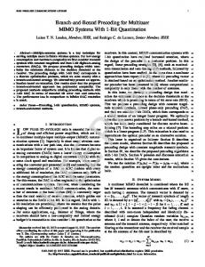
Fig. 2. Measurement setup in the alpine valley Drautal in Carinthia, Austria.
(21)
E. Post Equalization SINR The total deterministic interference caused by the pilot, control, and synchronization channels is given by s s s s γH = γp,H ˆ ˆ + γSCH,H ˆ + γSCH,H,τ ˆ .
UTM coordinates: 33T 353811mE 5178652mN 653 m.a.s.l.
(23)
Knowing all the above interference terms we can calculate the post equalization SINR [8, 9] of the ns -th data stream at the despreader output � � (n ) 2 PHS−PDSCH SF gs s Ns τ SINRest (ns ) = (n ) . (ns ) (ns ) (n ) (n )2 s γs,H + γs,H∆ + γH∆s + σv0 s ˆ + CγH ˆ (24) Here, SF is the spreading factor of the HS-PDSCH. The factor C is equal to 0 if the receiver uses interference cancelation of the synchronization, pilot, and control3 channels and equal to 1 if no interference cancelation is employed. If more advanced interference cancelation schemes like in [15] are (ns ) employed, also the term γs,H ˆ can be reduced. The stochastic interference terms can only be reduced by more advanced channel estimation algorithms, and/or by iterative receiver techniques that use decision directed channel estimation. IV. S IMULATIONS AND M EASUREMENTS The accuracy of the SINR estimation was evaluated by link level simulations and outdoor measurements. In the simulations, we used an uncorrelated ITU Pedestrian B channel model [16]. The measurements were carried out in the alpine valley Drautal in Carinthia, Austria and utilized the Vienna MIMO testbed described in detail in [7] and [17–19]. The transmitter and receiver were placed on the opposing sides of the valley4 in a distance of 5.7 km (Fig. 2). At the transmitter, 3 Note that we assume here that the control channel can be detected error free due to the large spreading factor of 256 which provides a large spreading gain and thus high SNR. 4 Detailed transmitter and receiver positions can be downloaded for Google Earth at http://www.nt.tuwien.ac.at/fileadmin/data/testbed/ Carinthia-RX-TX-GPS.kmz
we utilized a Kathrein 800 10543, 60◦ XX-pol basestation panel antenna [20] with ±45◦ polarization. A center frequency of 2.5 GHz and a maximum transmit power level of 39 dBm was used. At the receiver, four Linksysr 5 dBi rod antennas pointing into different directions were mounted on a brass sheet in the size of the top of a Linksys WLAN router. The receive antennas were rotated and moved by an XYΦpositioning table to generate 784 channel realizations within an area of 3 λ×3 λ (36 cm×36 cm). At every position we measured twelve different transmit power levels. The measurements were carried out using the following procedure: At every receive antenna position and transmit power value, we first transmitted one HSDPA subframe which was evaluated in a “mini-receiver”. This mini-receiver only performed synchronization, channel estimation and subsequently the CQI and PCI calculation. The CQI and the PCI value was then fed back to the transmitter which transmitted an HSDPA subframe corresponding to the CQI and PCI value. This subframe was then stored at the receiver for later off-line evaluation. More details about the measurement procedure can be found in [21]. In the off-line data evaluation, we employed a low complexity LMMSE channel estimator [22] with three iterations at the receiver. The iterations were required to alternately improve the channel estimate and the channel autocorrelation estimate. The channel estimate was then used to calculate an estimate of the deterministic part of the receive signals (synchronization and pilot signal) which were subtracted from the received signal to perform interference cancelation. A subsequent LMMSE equalizer [21] was then applied to obtain an estimate of the transmitted data chip stream. Compared to the optimum ML receiver [23], LMMSE equalization with interference cancelation provides a good performance/complexity tradeoff. Log-likelihood values of the received bits were calculated in a soft max-log-MAP demapper and further processed in a Turbo decoder with eight iterations. If the CRC of the HSDPA subframe was correct, the number of data bits was considered in the throughput calculation. If the CRC failed, the data throughput of this frame was set to zero.
Copyright 2001 SS&C. Published in the Conference Record of the Fourtysecond Asilomar Conference on Signals, Systems and Computers, 2008, October 26-29, 2008, Pacific Grove, CA, USA.
20
20 2x2 D-TxAA
2x2 D-TxAA
15
15
10
2x2 TxAA 1x2 SIMO
5
10
2x2 TxAA
2x1 TxAA
2x1 TxAA
1x2 SIMO 1x1 SISO
post equalization SINR [dB]
35 30
0 45 40
estimated SINRest
estimated SINRest 2x2 TxAA
observed SINR
observed SINR
35 30
2x2 TxAA
25 20 15
25 1x2 SIMO
2x2 D-TxAA Stream 1 & 2
10
1x2 SIMO
2x2 D-TxAA Stream 1 & 2
1x1 SISO
0 -5
0
5
15
20
25
30
Ior/Ioc [dB] Fig. 3.
5
10
15
15 5
1x1 SISO 10
20 10
2x1 TxAA
2x1 TxAA
5 -5 -10
5
1x1 SISO
0 45 40
25
throughput [Mbit/s]
MEASUREMENT non-urban outdoor-to-indoor tap-wise LMMSE channel estimation
0 20
25
30
35
40
post equalization SINR [dB]
throughput [Mbit/s]
25
SIMULATION uncorrelated ITU Pedestrian B channel perfect channel knowledge
-5
total transmit power [dBm]
Simulated (left side) and measured (right side) throughput and post equalization SINRs.
V. R ESULTS The results of our simulations and measurements are shown in Fig. 3 in form of throughput and SINR plots. The plots on the left side in Fig. 3 are obtained by physical layer simulations with perfect channel knowledge at the receiver. The plots on the right side in Fig. 3 are obtained by measurements with channel estimation at the receiver. The “observed SINR” in Fig. 3 is the SINR observed at the demapper input and is obtained as follows: Consider the transmitted data symbol vector d(ns ) of the ns -th symbol stream and the corresponding received symbol vector at the demapper ˆ (ns ) . The “observed” or “true” post equalization SINR input d is given by kd(ns ) k22 SINR = . (25) (n ˆ s ) − d(ns ) k2 kd 2
In the simulations, we observe a very good fit of the estimated SINRs (calculated according to Equ. (24)) over the full Ior /Ioc (ratio of the energy of the desired basestation to the energy of the interfering basestations) range. The SINR increases linearly with increasing Ior /Ioc . The estimated SINRs in the measurements also show a good fit at all transmit powers. In contrast to the simulations, the SINR saturates at about 30 dB
which is caused by residual interference due to the channel estimation error. In the measured scenario, the 2×1 TxAA system almost achieves the performance of the 1×2 SIMO system, whereas in the simulations a larger distance of almost 5 dB is observed. The large distance in the simulation is caused by the rather large delay spread of the Pedestrian B channel model. At such a large delay spread, the precoding with a complex scalar for every transmit antenna is far from optimal. In our measurements, however, the channel has a very small delay spread (about three chips) and thus the precoding works very well. In Fig. 4, the individual post equalization interference terms of the 2×2 TxAA system are shown over Ior /Ioc . Below Ior /Ioc ≈ 10 dB, the system performance is mainly dominated by the post equalization noise. Above Ior /Ioc > 10 dB, the deterministic interference of pilot and synchronization channel becomes dominant and has to be canceled to achieve high performance. If interference cancelation is performed, the system performance at high Ior /Ioc ≈ 10 is mainly dominated by the channel estimation error.
Copyright 2001 SS&C. Published in the Conference Record of the Fourtysecond Asilomar Conference on Signals, Systems and Computers, 2008, October 26-29, 2008, Pacific Grove, CA, USA.
interference of pilot, control, and synchronization channels: - stochastic part: - deterministic part: - deterministic self interference of data channels:
relative interference and noise terms
100
[3]
[4]
total interference and noise: - without interference cancelation: - with interference cancelation: - noise:
[5]
[6]
10-1 [7]
10-2 [8]
10-3 [9]
10-4
[10]
10-5 −10
0
10
Ior/Ioc [dB]
20
30 [11]
Fig. 4. Interference terms for a two receive antennas TxAA transmission over an uncorrelated ITU Pedestrian B channel. [12]
VI. C ONCLUSIONS In this work, we evaluated a throughput-maximizing method that jointly determines the CQI and the PCI value. The method was implemented in a physical layer link level simulator where a very good agreement between the estimated and the true post equalization SINR was achieved. Measurements with our testbed also showed a very good agreement between the estimated and the true SINR. A detailed analysis of the post equalization interference terms proofs that the performance at large receive SNRs is limited by interference caused by pilot and synchronization channels and by residual interference due to channel estimation errors. Therefore, interference cancelation as well as high performance channel estimation techniques have to be implemented in a MIMO HSDPA receiver in order to achieve high data throughput.
[13]
[14]
[15]
[16] [17]
[18]
ACKNOWLEDGMENTS The authors would like to thank the C12 project team for their work on the HSDPA simulator and fruitful discussions. We would also like to thank Walter Sch¨uttengruber for his tireless support on the Vienna MIMO testbed. This work has been funded by the Christian Doppler Laboratory for Design Methodology of Signal Processing Algorithms and the Institute of Communications and Radio Frequency Engineering. R EFERENCES [1] 3GPP, “Technical specification group radio access network; physical layer procedures (FDD) (Tech. Spec. 25.214 V7.7.0),” Nov. 2007. [Online]. Available: http://www.3gpp.org/ftp/Specs/html-info/25214.htm [2] S. McBeath, M. Ahmed, and K. Rohani, “Impact of imperfect estimators on W-CDMA receiver performance with MIMO antenna systems,” vol. 2, pp.
[19]
[20] [21]
[22]
[23]
1152–1156, Oct. 2003. [Online]. Available: http://ieeexplore.ieee.org/iel5/9004/ 28569/01285202.pdf?arnumber=1285202 Motorola and Nokia, “Revised HSDPA CQI proposal,” 3GPP, Tech. Rep. TSGRAN Working Group 4 Meeting #22, R4-020612, Apr. 2002. [Online]. Available: http://www.3gpp.org/ftp/tsg ran/WG4 Radio/TSGR4 22/Docs/R4-020612.zip S. Narayanaswamy and M. Rupp, “Antenna diversity in wireless communication terminals,” US Patent 5,905,467, 1999. [Online]. Available: http://www. freepatentsonline.com/5905467.html E. Zacarias, S. Werner, and R. Wichman, “Partial update adaptive transmit beamforming with limited feedback,” in Proc. IEEE International Conference on Acoustics, Speech, and Signal Processing (ICASSP 2006), Toulouse, France, May 2006. [Online]. Available: http://ieeexplore.ieee.org/iel5/11024/34760/01661070. pdf?tp=&isnumber=&arnumber=1661070 E. Zacarias, “Adaptive transmit beamforming with closed loop feedback in MIMO systems,” Signal Processing Laboratory, Helsinki University of Technology, Tech. Rep., 2004. [Online]. Available: http://www.comlab.hut.fi/opetus/333/2004 2005 slides/txbf closed loop text.pdf S. Caban, C. Mehlf¨uhrer, R. Langwieser, A. L. Scholtz, and M. Rupp, “Vienna MIMO testbed,” EURASIP Journal on Applied Signal Processing, Special Issue on Implementation Aspects and Testbeds for MIMO Systems, vol. 2006, Article ID 54868, 2006. [Online]. Available: http://publik.tuwien.ac.at/files/pub-et 10929.pdf A. Szabo, N. Geng, A. Seeger, and W. Utschick, “Investigations on link to system level interface for MIMO systems,” in Proc. 3rd International Symposium on Image and Signal Processing and Analysis (ISPA2003), pp. 365–369, Rome, Italy, Sept. 2003. [Online]. Available: http://ieeexplore.ieee.org/iel5/9084/28837/ 01296924.pdf?tp=&isnumber=&arnumber=1296924 M. Wrulich, S. Eder, I. Viering, and M. Rupp, “Efficient link-to-system level model for MIMO HSDPA,” in Proc. of the 4th IEEE Broadband Wireless Access Workshop, 2008. S. Geirhofer, C. Mehlf¨uhrer, and M. Rupp, “Design and real-time measurement of HSDPA equalizers,” in Proc. of the 6th IEEE Workshop on Signal Processing Advances in Wireless Communications (SPAWC 2005), pp. 166–170, New York City, USA, June 2005. [Online]. Available: http://publik.tuwien.ac.at/files/pub-et 9722.pdf L. Mailaender, “Linear MIMO equalization for CDMA downlink signals with code reuse,” IEEE Transactions on Wireless Communications, vol. 4, no. 5, pp. 2423– 2434, Sept. 2005. [Online]. Available: http://ieeexplore.ieee.org/iel5/7693/ 32683/01532226.pdf M. Wrulich, C. Mehlf¨uhrer, and M. Rupp, “Interference aware MMSE equalization for MIMO TxAA,” in Proc. Third International Symposium on Communications, Control, and Signal Processing (ISCCSP 2008), pp. 1585–1589, St. Julians, Malta, Mar. 2008. [Online]. Available: http://publik.tuwien.ac.at/files/pub-et 13657.pdf C. Mehlf¨uhrer, M. Wrulich, and M. Rupp, “Intra-cell interference aware equalization for TxAA HSDPA,” in Proc. IEEE International Symposium on Wireless Pervasive Computing (ISWPC 2008), pp. 406–409, Santorini, Greece, May 2008. [Online]. Available: http://publik.tuwien.ac.at/files/pub-et 13749.pdf B. Hassibi and B. Hochwald, “How much training is needed in multiple-antenna wireless links?” Information Theory, IEEE Transactions on, vol. 49, no. 4, pp. 951–963, Apr. 2003. [Online]. Available: http://ieeexplore.ieee.org/stamp/stamp. jsp?arnumber=1193803 D. Bosanska, C. Mehlf¨uhrer, and M. Rupp, “Performance evaluation of intra-cell interference cancelation in D-TxAA HSDPA,” in Proc. International ITG Workshop on Smart Antennas (WSA 2008), Darmstadt, Germany, Feb. 2008. [Online]. Available: http://publik.tuwien.ac.at/files/pub-et 13677.pdf “Recommendation ITU-R M.1225: Guidelines for evaluation of radio transmission technologies for IMT-2000,” Tech. Rep., 1997. C. Mehlf¨uhrer, S. Caban, and M. Rupp, “Experimental evaluation of adaptive modulation and coding in MIMO WiMAX with limited feedback,” EURASIP Journal on Advances in Signal Processing, Special Issue on MIMO Systems with Limited Feedback, vol. 2008, Article ID 837102, 2008. [Online]. Available: http://publik.tuwien.ac.at/files/pub-et 13762.pdf C. Mehlf¨uhrer, S. Geirhofer, S. Caban, and M. Rupp, “A flexible MIMO testbed with remote access,” in Proc. of the 13th European Signal Processing Conference (EUSIPCO 2005), Antalya, Turkey, Sept. 2005. [Online]. Available: http://publik.tuwien.ac.at/files/pub-et 9732.pdf M. Rupp, C. Mehlf¨uhrer, S. Caban, R. Langwieser, L. W. Mayer, and A. L. Scholtz, “Testbeds and rapid prototyping in wireless system design,” EURASIP Newsletter, vol. 17, no. 3, pp. 32–50, Sept. 2006. [Online]. Available: http://publik.tuwien.ac.at/files/pub-et 11232.pdf Kathrein, “Technical specification Kathrein antenna type no. 800 10543.” [Online]. Available: http://www.kathrein-scala.com/catalog/80010543.pdf C. Mehlf¨uhrer, S. Caban, and M. Rupp, “Measurement based evaluation of low complexity receivers for D-TxAA HSDPA,” in Proc. of the 16th European Signal Processing Conference (EUSIPCO 2008), Lausanne, Switzerland, Aug. 2008. [Online]. Available: http://publik.tuwien.ac.at/files/PubDat 166132.pdf C. Mehlf¨uhrer and M. Rupp, “Novel tap-wise LMMSE channel estimation for MIMO W-CDMA,” in Proc. 51st Annual IEEE Globecom Conference, 2008, New Orleans, LA, USA, Nov. 2008. M. Rupp, M. Guillaud, and S. Das, “On MIMO decoding algorithms for UMTS,” in Conference Record of the Thirty-Fifth Asilomar Conference on Signals, Systems and Computers, 2001, vol. 2, pp. 975–979, Nov. 2001. [Online]. Available: http://ieeexplore.ieee.org/iel5/7744/21273/00987640.pdf?tp= &isnumber=&arnumber=987640
Reference: C. Mehlführer, S. Caban, M. Wrulich, and M. Rupp, "Joint Throughput Optimized CQI and Precoding Weight Calculation for MIMO HSDPA," in Conference Record of the Fourtysecond Asilomar Conference on Signals, Systems and Computers, 2008, Pacific Grove, CA, USA, Oct. 2008. [Online]. Available: http://publik.tuwien.ac.at/files/PubDat_167015.pdf BibTeX: @InProceedings{Mehlfuehrer08_Asilomar, author = {Christian Mehlf\"uhrer and Sebastian Caban and Martin Wrulich and Markus Rupp}, title = {Joint Throughput Optimized {CQI} and Precoding Weight Calculation for {MIMO} {HSDPA}}, booktitle = {Conference Record of the Fourtysecond Asilomar Conference on Signals, Systems and Computers, 2008}, month = oct, year = 2008, address = {Pacific Grove, CA, USA}, url = {http://publik.tuwien.ac.at/files/PubDat_167015.pdf} }