Grid for 3GPP LTE. Andreas Ibing, Volker Jungnickel. Fraunhofer Institute for Telecommunications. Heinrich-Hertz-Institut. Einsteinufer 37, 10587 Berlin, ...
Joint Transmission and Detection in Hexagonal Grid for 3GPP LTE Andreas Ibing, Volker Jungnickel Fraunhofer Institute for Telecommunications Heinrich-Hertz-Institut Einsteinufer 37, 10587 Berlin, Germany
Abstract—Cooperative joint transmission and detection algorithms have a high potential to increase the capacity of cellular radio systems. This paper proposes a mapping of areas of joint signal processing into the cellular hexagonal grid architecture, balancing network load, computational load and physical layer overhead versus interference reduction gain. The proposed communication architecture is shown to be realizable with offthe-shelf hardware.
I. I NTRODUCTION Modern wireless communication systems like 3GPP LTE [1] use orthogonal multicarrier modulation to avoid intra-cell interference. The remaining factor limiting system capacity is inter-cell interference, against which base station cooperation has recently gained interest. In the draft LTE standard, base station cooperation is limited to quasi-static (time granularity of some seconds) interference mitigation. Interference mitigation means that base station schedulers negotiate transmit power restrictions in certain frequency subbands or time intervals. Cancelling inter-cell interference requires tighter base station cooperation, which is joint signal processing [2]. Joint detection and transmission with a central signal processing unit is discussed e.g. in [2]. In current cellular systems, remote radio heads are often used. Remote radio heads can be set up at larger distances from the base station and are connected point-to-point over standardized optical interfaces (CPRI [3] or OBSAI [4]) transporting digital base band samples. Increasing the number of antennas per station in an interference limited system does not increase system capacity very much and poses difficulties both with RF costs and social feasibility (many people dislike a growing number of antennas on their roof). Therefore the idea is to rather tackle inter-cell interference by sharing antennas between base stations over a high-throughput low-delay IP network. While the hexagonal grid had been chosen for legacy systems with frequency reuse 7, the available sites are to be kept for practical reasons for new systems like LTE with frequency reuse 1. This paper proposes a mapping of the so far central processing unit into the hexagonal grid structure in a realizable, distributed and scaleable way.
II. T RADEOFFS FOR CELLULAR COOPERATIVE MIMO-OFDM On the one hand, the area of joint signal processing (group of cooperating base stations) should be as large as possible to achieve high interference reduction gain [5]. On the other hand, there are several factors which limit the geographical area of cooperation and the number of cooperating stations. In OFDM systems, the cyclic prefix (CP) is designed to be longer than channel delay spread, so that the channel impulse response from the previous OFDM symbol decays in the CP (otherwise there would be intersymbol interference). For cooperative MIMO-OFDM, additionally propagation delay differences between cooperating stations must be supported by means of a longer CP, which of course increases overhead. As the number of jointly processed antenna signals increases, channel estimation (based on pilot symbols) must be possible for more antennas. This results in either more overhead due to increased number of pilots or worsening of estimation performance due to joint channel estimation (SNR degradation) [6] if the same mobility is to be supported by the system. Capacity of the backbone connecting cooperating stations is limited in terms of network load and network delay. Available computational power is another limit for joint signal processing, which essentially has a cubical complexity with regard to number of antennas. The interference situation is also influenced by antenna orientation. Our aim is therefore to find a suitable network architecture (based on 3GPP LTE) which balances physical layer overhead, network load and computational load on the one hand and interference reduction gain on the other. III. P ROPOSED A RCHITECTURE A. Cooperating Stations In the current hexagonal grid it is not clear which sectors should be jointly processed (it was designed to have no distinct interferers). A mapping into another hexagonal grid with exactly the same base station positions is possible
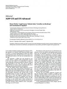
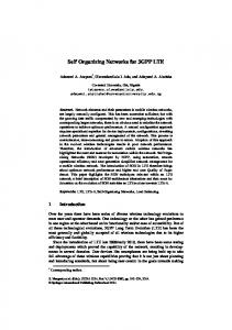
by rotating sectorization 90 degrees (see figure 1). The resulting hexagonal cells are 3 times larger in area. Before, there were 3 cells (sectors) per base station, while with the mapping there is one cell per base station. In the new hexagonal grid (with frequency reuse 1), a terminal normally receives strong signals from three base stations (figure 2). The antennas offering most performance gain when cooperating thus belong to three sectors each from a different base station. Each location in the system can be mapped to such three sectors of three different base stations. These sectors therefore offer the starting point for possibly growing areas of cooperation in the future. Another mapping without rotating the base stations and with the same old cell size can be done by introducing more base stations (see fig. 4). The same joint processing approach can be used.
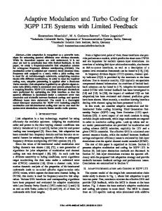
In figure 3 the processing for service area m is located in base station m. Between the base station and its two remote sectors (hosted by two neighbouring base stations) base band samples are exchanged for uplink and downlink. Different from dedicated CPRI/OBSAI links, the exchange is done over the Internet using UDP/IP. To allow for piecewise central processing, the partitioning into service areas has been done non-overlapping. Between neighbouring service areas the well-known approaches of interference mitigation can of course still be applied.
BS 0 SA 1 BS n SA m BS 1 SA 2
BS m
BS 2 Fig. 1. The current hexagonal grid (left) can be modified into a new hexagonal grid with exactly the same base station positions (right) by rotating sectorization 90 degrees. The resulting grid is better suited for piecewise joint processing.
Fig. 3. Mapping joint signal processing areas into the hexagonal grid: signals in area ’SA m’ are jointly processed by base station ’BS m’. Each base station processes samples from one local and two remote sectors, and offers the other two local sectors for remote processing.
C. Two Types of Sectors One base station still handles data, protocol and signal processing for three sectors, but for three different ones, of which two are remote. Signal processing for the three sectors can now be done jointly to reduce inter-cell interference (before, the three local sectors were separated by sectorized antennas). Each base station now offers two sectors and their network connection for base band sample exchange to other base stations and jointly processes signals from the third and two remote sectors. IV. E VALUATION A. Network Load Fig. 2. In the new hexagonal grid a terminal normally receives strong signals from three neighbouring base stations.
B. Communication and Computation The whole area covered by the system can be partitioned into disjunct areas, each consisting of three sectors belonging to three different base stations. Joint signal processing is applied to each such three-sector-area. Such an area of joint processing is termed ’service area’ in accordance with [2]. The resulting partitioning is depicted in figure 3. The processing for a service area is located in one base station.
Table I shows an estimate of the absolute required network bandwidth for different system configurations of a 20MHz LTE system. Overhead due to network protocol headers is not included. It is assumed that a base station has exactly one wired connection to its router, and the numbers given are receive and transmit bandwidth on this link. The network traffic through the base station consists of three parts. First there are packets exchanged with the gateway, for all data streams of the service area. Second, baseband samples are exchanged with the two remote sectors of the service area. And third, the base station hosts two sectors, for which the samples are processed elsewhere.
TABLE II C OMPUTATIONAL REQUIREMENTS Configuration 1 antenna per sector, no cooperation 4 antennas per sector, no cooperation 1 antenna per sector, cooperation 4 antennas per sector, cooperation
computational increase factor 1 64 9 576
shows computational increase factors for different system configurations in comparison to a non-cooperative base station feeding three sectors with one antenna each. C. Delay Requirements
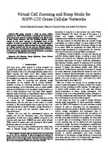
Fig. 4. The proposed architecture can also be implemented with the current cell size and without rotating sectorization, by introducing more base stations (red dots). TABLE I N ETWORK L OAD Configuration 1 antenna per sector, no cooperation 4 antennas per sector, no cooperation 1 antenna per sector, cooperation 4 antennas per sector, cooperation
Rx and Tx Load 150 MBit/s 600 MBit/s 1,8 GBit/s 7,1 GBit/s
While the LTE draft standard supports up to two concurrent data streams, the table also considers a 4x4 configuration (4 data streams per sector). A system with three cooperating sectors of 4 antennas each can algorithmically be treated as a 12x12 system (up to 12 concurrent data streams). An attractive processing scheme is space division multiple access (SDMA), i.e. distributing the 12 data streams between several terminals which can handle up to 2 or 4 data streams each. One data stream in LTE can transport up to around 50MBit/s (64QAM, between base station and gateway, without protocol overhead). For three sectors with one data stream each and without cooperation the sum is therefore 150MBit/s for downlink and the same for uplink. For exchange of baseband samples it is assumed that the quantization is 12 bit for inphase and quadrature component each, and that the exchange is done in frequency domain (1200 subcarriers), which saves the overhead of exchanging guard band samples. With 14 OFDM symbols per 1ms and 1200 samples per OFDM symbol, the resulting data rate per remote antenna is around 400 MBit/s (without protocol overhead). B. Computational Requirements It is assumed that the limiting factor is computation of MIMO equalization matrices. As this includes matrix inversion, the algorithm essentially grows cubically with the number of jointly processed antenna signals. Table II
The round-trip time over the air is envisioned to be around 10ms (one radio frame). This round-trip time should not be limited by the network delay which is added by cooperation. Processing time from receive to transmit will be around 5ms. The network delay of transporting samples of one Transmission Time Interval (TTI, 1ms) between base stations should therefore not exceed around 1ms. D. Performance of Current Network Infrastructure While the depicted throughput requirements can be met with currently available routers, the delay requirements are investigated in the following. Sources for network delay are [7]: • Forwarding delay: the time needed by a router for packet reception, routing decision and begin of transmission (if there are no packets in the queue). This time constant depends on the router implementation and is around 10−6 s. • Queueing delay: the waiting time of a packet in a queue. This time can be eliminated for a moderate amount of high-priority traffic using priority scheduling (Differentiated Services [8]). • Propagation delay: the time needed by the electric field to cross the link. • Serialization delay: the time needed to shift the bits of a packet onto the line. It depends on the size of the packet and the speed of the port. It is therefore assumed that the network delay between two base stations over two or three routers for a 1500 Byte packet (Ethernet maximum transfer unit) is below 100 micro seconds. The delay component which is dependent on the amount of data transported is the serialization delay. In the following it is assumed that processing is done on whole subframes (TTI). Therefore the network delay of exchanging all data belonging to one TTI between cooperating stations is derived. Over the cable connecting base station and router, sample data for four sectors is exchanged in both directions as described in section IV-A. Again exchange of frequency domain samples is assumed, UDP/IP overhead is ignored. The following table gives the delay values for different system configurations. Variation of the number of cooperating antennas and variation of the line speed both
TABLE III N ETWORK D ELAY Configuration 1 antenna per sector, 10GBit/s 1 antenna per sector, 40GBit/s 4 antennas per sector, 10GBit/s 4 antennas per sector, 40GBit/s
Network Delay for one TTI 260 µs 140 µs 750 µs 260 µs
influence serialization delay. The numbers are smaller than one TTI and thus in the order of channel coherence time for high-mobility users. E. Propagation Delay Differences and Cyclic Prefix Length LTE with 20MHz bandwidth uses a 2048-FFT with 15kHz subcarrier spacing, which gives a sample frequency of 30.72MHz. One sample on the air is therefore around 10 meters long, and one kilometer difference corresponds to around 100 samples. The normal LTE CP length is 144 samples. Delay spread also increases with distance. To account for one kilometer delay difference (urban deployment), a new CP length of around 300 samples seems reasonable (15% overhead). F. Synchronisation In uplink, all base stations can independently be synchronized to a transmitting terminal. In downlink, joint transmission requires coherent transmission on the involved antennas and thus a means to synchronize at least the antennas belonging to the same service area. While CPRI/OBSAI links to remote antennas support synchronization, an IP connection over the Internet of course does not. LTE is envisioned to be a synchronized single frequency network [1]. Aside from the unrealistic assumption of a common synchroneous network interface like SONET/SDH, there are basically two possibilities for base station synchronisation. 1) Over the air: If a time division multiplex component for transmissions of different base stations can be assumed in the frame structure (one base station receives while the other transmits), the base stations could be iteratively synchronized to one master base station using fine frequency synchronization algorithms. In frequency division duplex, the approach is to use uplink-via-downlink synchronisation for the terminals (in uplink there are no preambles in LTE) and carrier frequency offset estimation feedback from the terminals to synchronize the base stations. The basic algorithm for decentralized synchronisation over the air is [9]. 2) With external system: The base stations can be synchronized using the GPS time signal and a high-precision (atomic) oscillator. The GPS time signal has an accuracy around 100 ns [10], which in the maximum bandwidth LTE mode corresponds to 3 samples. The frequency is given by the atomic oscillator (frequency standard).
G. Channel Estimation and Pilot Structure Pilot symbols are used to identify channel coefficients from transmit antennas. The density of pilots over time determines the minimum supported channel coherence time (limits supported mobility). The density of pilots in frequency domain limits accuracy of channel estimation (interpolation). Pilot symbols are of course overhead. The extended channel state information needed for joint detection and transmission can be obtained in two ways, which could be combined. 1) Dedicated Pilots: In LTE, the antennas of one sector have dedicated pilot positions: when one antenna transmits a pilot, the other antennas of this sector don’t transmit on the same subcarrier. Using dedicated pilots in this way, with one pilot symbol of a transmit antenna a column of the channel matrix is obtained at the receiver. The use of dedicated pilots scales badly for base station cooperation. Extending the 2 antenna LTE pilot structure to 3 cooperative sectors with 4 antennas each (12 cooperating antennas) results in more than 50% overhead caused by the pilots. 2) Joint Channel Estimation: When antennas transmit pilots at the same time on the same resource, the receiver can perform joint channel estimation, e.g. according to the MMSE criterion [6]. The price for the reduced pilot overhead is SNR degradation. Filtering can be done both over time and frequency. V. C ONCLUSION A mapping of areas of joint transmission and detection into the cellular hexagonal grid has been given. The resulting system consists of larger areas without intra-area interference. Network load, network delay, computational load and increase in physical layer overhead have beeen evaluated. The architecture is scalable in coarse steps by varying the antenna numbers and service area bandwidths (the same way in which LTE is scalable). The evaluation shows that jointly processing the proposed three sectors is possible with currently available hardware. The architecture offers the possibility for optimizing the pilot structure inside a service area. R EFERENCES [1] 3GPP TSG RAN: TS36.300v8.1.0 E-UTRA and E-UTRAN; Overall Description; Stage 2, 3GPP, June 2007. [Online]. Available: http://www.3gpp.org/ftp/Specs/html-info/36300.htm [2] T. Weber, I. Maniatis, A. Sklavos, Y. Liu, E. Costa, H. Haas, and E. Schulz, “Joint transmission and detection integrated network (joint), a generic proposal for beyond 3g systems,” in 9th International Conference on Telecommunications (ICT’02), vol. 3, Beijing, China, June 2002, pp. 479–483. [3] Common Public Radio Interface. [Online]. Available: http://www. cpri.info [4] Open Base Station Architecture Initiative, ’Reference Point 3 Specification Version 4.0’. [Online]. Available: http://www.obsai.org [5] W. Zirwas, E. Schulz, M. Schubert, W. Mennerich, V. Jungnickel, and L. Thiele, “Cooperative Antenna Concepts for Interference Mitigation,” in 13th European Wireless Conference, Paris, France, Apr. 2007. [6] I. Maniatis:, “Joint channel estimation in service area based ofdm air interfaces for beyond 3g mobile radio systems,” Ph.D. dissertation, Technical University of Kaiserslautern, feb. 2005.
[7] C. Semeria and J. Stewart, “Supporting differentiated service classes in large ip networks.” [Online]. Available: www.juniper.net/solutions/ literature/whitepapers/200019.pdf [8] “Rfc 2474: Definition of the differentiated services field (ds field) in the ipv4 and ipv6 headers.” [Online]. Available: http: //www.ietf.org/rfc/rfc2474.txt?number=2474 [9] Y. Akaiwa, H. Andoh, and T. Kohama, “Autonomous decentralized inter-base-station synchronization for tdma microcellular systems,” Vehicular Technology Conference, 1991., 41st IEEE, pp. 257–262, 19-22 May 1991. [10] J. Wechsler, “The role of gps in precise time and frequency dissemination.” [Online]. Available: http://www.pdana. com/PHDWWWfiles/gpsrole.pdf


![3GPP LTE: An Overview - IAENG [PDF]](https://m.moam.info/img/260x300/3gpp-lte-an-overview-iaeng-pdf_648406b4098a9ec44c8b458d.jpg)

![3GPP SAE/LTE Security - Niksun [PDF]](https://m.moam.info/img/260x300/3gpp-sae-lte-security-niksun-pdf_64b178da098a9e8f018b45fd.jpg)