Hindawi Publishing Corporation International Journal of Antennas and Propagation Volume 2016, Article ID 4341068, 10 pages http://dx.doi.org/10.1155/2016/4341068
Research Article Joint User Scheduling and MU-MIMO Hybrid Beamforming Algorithm for mmWave FDMA Massive MIMO System Jing Jiang and Deting Kong College of Communication and Information Engineering, Xi’an University of Posts and Telecommunications, Xi’an, Shaanxi, China Correspondence should be addressed to Deting Kong; echo
[email protected] Received 2 August 2016; Accepted 9 October 2016 Academic Editor: Hassan T. Chattha Copyright © 2016 J. Jiang and D. Kong. This is an open access article distributed under the Creative Commons Attribution License, which permits unrestricted use, distribution, and reproduction in any medium, provided the original work is properly cited. The large bandwidth and multipath in millimeter wave (mmWave) cellular system assure the existence of frequency selective channels; it is necessary that mmWave system remains with frequency division multiple access (FDMA) and user scheduling. But for the hybrid beamforming system, the analog beamforming is implemented by the same phase shifts in the entire frequency band, and the wideband phase shifts may not be harmonious with all users scheduled in frequency resources. This paper proposes a joint user scheduling and multiuser hybrid beamforming algorithm for downlink massive multiple input multiple output (MIMO) orthogonal frequency division multiple access (OFDMA) systems. In the first step of user scheduling, the users with identical optimal beams form an OFDMA user group and multiplex the entire frequency resource. Then base station (BS) allocates the frequency resources for each member of OFDMA user group. An OFDMA user group can be regarded as a virtual user; thus it can support arbitrary MU-MIMO user selection and beamforming algorithms. Further, the analog beamforming vectors employ the best beam of each selected MU-MIMO user and the digital beamforming algorithm is solved by weight MMSE to acquire the best performance gain and mitigate the interuser inference. Simulation results show that hybrid beamforming together with user scheduling can greatly improve the performance of mmWave OFDMA massive MU-MIMO system.
1. Introduction Millimeter wave (mmWave) communication will unleash the 30–300 GHz new spectrum and enabled gigabit-per-second data rates for the next generation mobile cellular systems [1–3]. Massive MIMO is an essential part of mmWave communication to combat the stringent constraints imposed by the high propagation loss. A beneficial feature of millimeter wave is that large-scale antenna arrays can be packed into small dimensions thanks to the very small wavelength [4, 5]. However, the digital processing in traditional MIMO system requires dedicated baseband and RF hardware for every antenna element. With the large-scale antenna, the high cost and power consumption of mmWave RF hardware preclude such a transceiver architecture at present. In mmWave massive MIMO system, the trade-off between performance and simplicity drives the need to deploy beamforming at both the digital and analog domains, that is, hybrid beamforming. Most current hybrid beamforming algorithms [6–8] assume user scheduling based on STDMA that a single user
or multiple spatial multiplexing users are scheduled in the entire frequency band at a given time slot. Actually, the large bandwidth and multipath nature of mmWave channels in a cellular system assure the existence of frequency selective channels; it is necessary that mmWave communication remains with frequency division multiple access (FDMA) and user scheduling. OFDMA provides a natural multiple access method by assigning different users with orthogonal subcarriers, and multiuser diversity gain in frequency domain can be exploited by multiuser subcarrier scheduling [9, 10]. But for the hybrid beamforming system, the analog beamforming is implemented by the phase shifts which are constant in the entire frequency band. There are multiple frequency multiplexing users in the entire frequency band; they will experience the same analog beamforming processing. Thus it needs a joint optimization of user scheduling and the wideband processing of the analog beamforming. On the other hand, mmWave links are inherently directional, and the antenna array steers its beam towards any direction electronically and to achieve a high gain at this direction,
2
International Journal of Antennas and Propagation
while offering a very low gain in all other directions. It is beneficial for MU-MIMO because the RF beams have sufficient degrees of freedom to be optimized for MUMIMO. In this paper, we will design the joint user scheduling and MU-MIMO hybrid beamforming scheme for mmWave massive MIMO-OFDMA system. References [11, 12] have meaningful researches on OFDMA scheduling for the hybrid beamforming system. Reference [11] computes the analog beamforming matrix as the first 𝑁𝑎 eigenvectors of the left singular value decomposition (SVD) of the combined digital precoding matrices of subcarriers having the highest sum rate (𝑁𝑎 is the amount of RF chains). Then, for fixed A, the digital beamforming matrix is computed and its corresponding users are scheduled such that the total sum rate is maximized for each subcarrier. Reference [12] enables users with high cochannel interference to be scheduled in different frequency channels in the same time slot while sharing the same RF chain and analog beam. For MU-MIMO hybrid beamforming algorithms, [13] considers the zero forcing (ZF) hybrid beamforming which essentially applies phase-only control at the RF domain and then performs a low-dimensional baseband ZF precoding based on the effective channel seen from baseband. Reference [14] designs the hybrid beamforming by considering a weighed sum mean-square error (WSMSE) minimization problem incorporating the solution of the detected signals which is obtained from the block diagonalization technique. The resulting WSMSE problem is solved by applying the orthogonal matching pursuit algorithm. Reference [15] analyzes a low complexity hybrid precoding algorithm for downlink multiuser mmWave system, which configures the hybrid precoder at the transmitter and analog combiners at multiple receivers with a small training and feedback overhead. For this algorithm, a lower bound on the achievable rate for the case of single-path channels is derived. Reference [16] designs a hybrid block diagonalization scheme to approach the capacity performance of the traditional BD processing method, aiming to harvest the large array gain through the phase-only RF precoding and combining. In [11], the analog beamforming matrix is acquired from SVD or QR decomposition, so it is hard to implement with the phase shift of the traditional analog beamforming. Reference [12] considers that the base station applies only one RF chain to transmit signals to users scheduled in different frequency channels. Actually there will be several RF chains in mmWave communication; the scheduled user in multiple subbands could transmit signals from different RF chains. Considering the contradiction between the optimization of the wideband analog beamforming and multiple users scheduled in different frequency subbands, we propose a joint user scheduling and MU-MIMO hybrid beamforming scheme for mmWave OFDMA system. The contribution of this paper can be summarized as follows: (i) User scheduling algorithm achieves frequency resource allocation and MU-MIMO user selection. Firstly the users with identical optimal beams are defined as an OFDMA user group. For an OFDMA
user group, all members multiplex the entire frequency band and the one with the best channel gain is assigned in the corresponding frequency resources. Then the frequency domain channel of each OFDMA user group is defined as an integrated channel, which is regarded as a virtual user in MU-MIMO user selection and analog beamforming design. Finally MUMIMO users are selected to maximize the mmWave system throughput. (ii) An OFDMA user group can be regarded as a virtual user that the RF beam of every member is the same; thus the hybrid beamforming could not only coordinate the contradiction of the wideband analog beamforming and multiple users scheduled in frequency resource, but also support arbitrary RF number and MU-MIMO algorithms. (iii) For the proposed hybrid beamforming, the analog beamforming vectors adopt the optimal beam of each scheduled user, since the performance of each user is sensitive to beam direction. The digital beamforming algorithm is solved by weight MMSE, which not only achieves the optimal performance for the single user, but also mitigates the residual interuser interference. (iv) Evaluate the sum rate of the existing and the proposed MU-MIMO hybrid beamforming under different number of BS antenna and scheduling users. In the simulation, the proposed user scheduling algorithm in this paper is based on FDMA, whereas other reference algorithms are based on TDMA. Simulation results show that hybrid beamforming together with user scheduling can greatly improve the performance of mmWave OFDMA massive MU-MIMO system. The rest of this paper is organized as follows. Sections 2 and 3 introduce the system model and channel model. In Section 4, the proposed user scheduling algorithm is provided. In Section 5, the proposed hybrid beamforming algorithm is presented, and computer simulation results are shown in Section 6. Finally, conclusions are drawn in Section 7. Notations. In this paper, upper-case/lower-case boldface letters denote matrices/column vectors. X𝑇 , X𝐻, X−1 , and X(𝑖, 𝑗) denote transpose, conjugate transpose, inversion, and the (𝑖, 𝑗)th element of X, respectively. [X]𝑚𝑚 denotes the 𝑚th diagonal element of X. E(X) denotes the expected value of X. tr(X) denotes the trace of X. We define ‖X‖2𝐹 as tr(X𝐻X) and ‖X‖2 as the square root of the maximum eigenvalue of X𝐻X. I is an identity matrix with appropriate size; C𝑀×𝑀 represent spaces of 𝑀×𝑀 matrices with complex entries. The acronyms s.t and i.i.d denote “subject to” and “independent and identically distributed,” respectively.
2. System Model In this paper, we will consider downlink OFDMA MUMIMO mmWave system as shown in Figure 1. The BS with 𝑁𝑡 transmit antennas communicates 𝑁𝑠 data streams to 𝐾
International Journal of Antennas and Propagation
3
User 1
.. .
User scheduling User 2 Baseband Data streams for to select K beamformer Kall users MU-MIMO .. W . users .. . User K
.. .
IFFT & add CP
1
.. .
2
Nt .. .
RF beamformer F
.. .
Nr .. .
User 1
H
NRF
.. .
Nr .. .
BS side
User Kall
Figure 1: Block diagram of mmWave MU-MIMO system based on frequency domain user scheduling.
MU-MIMO spatial multiplexing users, which are selected out from all 𝐾all users; every user has 𝑁𝑟 antennas. To enable multistream communication, the transmitter is equipped with 𝑁RF transmit chains such that 𝑁𝑠 ≤ 𝑁RF ≤ 𝑁𝑡 . We employ resource block based OFDMA transmission where each block occupies 𝑁𝑓 adjacent subcarriers and 𝑁𝑜 consecutive OFDM symbols. At each time slot of duration 𝑇, the transmitter broadcasts 𝑁𝑏 blocks and 𝑁𝑏 is the amount of resource blocks [17, 18]. The transmitted data streams at the BS are assumed to be processed by a digital beamformer W in the baseband, followed by an analog beamformer F before transmission. Notably, F can realize only phase changes (phase-only control), since it is implemented using analog phase shifters; each entry of F is constrained to satisfying ‖F𝑖,𝑗 ‖ = 1/√𝑁𝑡 . Furthermore, the total power constraint is enforced by letting ‖FW‖2𝐹 = 𝑁𝑠 . For simplicity, we will describe the system model in frequency domain. Analog beamforming vector f in time domain will be transformed to F in frequency domain just by employing fast Fourier transform (FFT) operation. At the MS, a digital combiner B is used to process the received signal. Assume the transmitted signals of different users are independent from each other and from noises, the received signal Y𝑛,𝑘 ∈ C𝑁𝑡 ×1 of the 𝑘th user scheduled in the 𝑛th block can be written as Y𝑛,𝑘 =
B𝐻 𝑛,𝑘 H𝑛,𝑘 FW𝑛,𝑘 s𝑛,𝑘
+
(1)
+ B𝐻 𝑛,𝑘 n𝑛,𝑘 , 𝑁𝑠𝑛,𝑘 ×1
3. Channel Model Since mmWave channels are expected to have limited scattering, we adopt a geometric channel model with 𝐿 𝑘 rays for the channel of user 𝑘 in block 𝑛. Under this model, the channel H𝑛,𝑘 can be expressed as [12, 13] H𝑛,𝑘
denotes the transmitted signal vector where s𝑛,𝑘 ∈ C for 𝑘th user in the 𝑛th block, satisfying E[s𝐻 𝑛,𝑘 s𝑛,𝑘 ] = I, 𝐻 𝐻 E[s𝑛,𝑘s𝑛,𝑗 ] = 0, (𝑘 ≠ 𝑗), E[s𝑛,𝑘 n𝑛,𝑘 ] = 0, and 𝑁𝑠𝑛,𝑘 represents the number of the 𝑘th user’s data streams scheduled in the 𝑛,𝑘 𝑛th block. W𝑛,𝑘 ∈ C𝑁RF ×𝑁𝑠 denotes the transmitting digital beamformer for the 𝑘th user in the 𝑛th block, and F ∈ C𝑁𝑡 ×𝑁RF denotes the transmitting analog beamformer in the frequency domain which is FFT transformed by time domain 𝑛,𝑘 f, f = [f1 , f2 , . . . , f𝑁RF ]. B𝑛,𝑘 ∈ C𝑁𝑟 ×𝑁𝑠 denotes linear receive beamforming vectors to detect the transmit signals. H𝑛,𝑘 ∈ C𝑁𝑟 ×𝑁𝑡 denotes the MIMO channel of the 𝑘th user. n𝑛,𝑘 is
=√
𝐿
𝑁𝑟 𝑁𝑡 𝑠 ∑a (𝜑𝑅 , 𝜃𝑅 ) 𝛽 a𝑇 (𝜑𝑇 , 𝜃𝑇 ) , 𝐿 𝑠 𝜌𝑘 𝑙=1 𝑅 𝑙 𝑙 𝑙 𝑇 𝑙 𝑙
(2)
where 𝛽𝑙 is the channel impulse response of the 𝑙th path with E[|𝛽𝑙 |2 ] = 1 and 𝜌𝑘 is the path loss between BS and users. Considering the azimuth and elevation angles, the vectors a𝑇(𝜑𝑙𝑇 , 𝜃𝑙𝑇 ) and a𝑅 (𝜑𝑙𝑅 , 𝜃𝑙𝑅 ) represent the normalized transmit and receive array response vectors at an azimuth (elevation) angle of departure 𝜑𝑙𝑇 (𝜃𝑙𝑇 ) and that of arrival 𝜑𝑙𝑅 (𝜃𝑙𝑅 ), respectively. For a uniform planar array (UPA) in the 𝑥𝑦-plane with 𝑁row and 𝑁col elements on the 𝑥- and 𝑦-axes, respectively, the array response vector at the BS is given by [19] 𝑇 (])) a𝑇 (𝜑𝑙𝑇 , 𝜃𝑙𝑇 ) = vec (a𝑁row (𝜇) a𝑁col
=
𝐾
∑ B𝐻 𝑛,𝑘 H𝑛,𝑘 FW𝑛,𝑗 s𝑛,𝑗 𝑗=1,𝑗=𝑘 ̸
the vector of i.i.d additive complex Gaussian noise with zeromean and variance 𝜎2 .
1 [1, 𝑒𝑗] , . . . , 𝑒𝑗(𝑁col −1)] , 𝑒𝑗(𝜇+]) , . . . , √𝑁row 𝑁col
(3) 𝑇
𝑒𝑗(𝜇+(𝑁col −1)]) , . . . , 𝑒𝑗(𝑁row −1)𝜇 , . . . , 𝑒𝑗(𝑁row −1)𝜇+(𝑁col −1)] ] ,
𝜇 = 2𝜋𝑑𝑥 cos 𝜑 sin 𝜃/𝜆, ] = 2𝜋𝑑𝑦 sin 𝜑 sin 𝜃/𝜆, where 𝜆 is the wavelength and 𝑑𝑥 and 𝑑𝑦 are the distances between two adjacent antenna elements in the 𝑥- and 𝑦-axes, respectively. vec(⋅) denotes the matrix of dimension 𝑁row × 𝑁col stretches to the column vector of dimension 𝑁𝑡 × 1. The antenna array at the user side utilizes a uniform linear array (ULA); thus array response vectors at the user side are given by a𝑅 (𝜃𝑙𝑅 ) =
(4) 𝑇 1 [1, 𝑒𝑗(2𝜋/𝜆)𝑑 sin(𝜃) , . . . , 𝑒𝑗(𝑁𝑟 −1)(2𝜋/𝜆)𝑑 sin(𝜃) ] , √𝑁𝑟
where a𝑅 (𝜃𝑙𝑅 ) is the column vector of dimension 𝑁𝑟 × 1.
4
International Journal of Antennas and Propagation
4. User Scheduling Scheme This section discusses the proposed user scheduling algorithm and MU-MIMO user selection to maximize the total sum rate of all subcarriers, which can be treated as a stage prior to the hybrid beamforming design. This section is divided into three subsections. In the first subsection, we define OFDMA user groups that the users in a same group have identical RF beam and multiplex the whole frequency resource. In the second subsection, we allocate the frequency resource for each member and define each OFDMA group as a virtual user. In the last subsection, we select several MU-MIMO users which can maximize the mmWave system throughput. 4.1. OFDMA Group Selection. Firstly, users transmit uplink sounding signals, and BS uses the sounding results to select the strongest beam for every downlink user. According to the indices of the selected beams, the users which have identical selected beam form an OFDMA user group. OFDMA group selection problem is mathematically formulated as follows: User𝑖 , User𝑗 ∈ Ω𝑙OFDMA s.t.
opt 𝑓User𝑖
=
opt
4.2. Frequency Resources Allocation. The users in the same group will multiplex the entire frequency band. BS allocates the frequency resources for every member of OFDMA user group. To maximize the throughput of OFDMA system, the subcarrier or resource block is allocated to the user with the best channel gain. The scheduling process of the 𝑛th user in OFDAM user group Ω𝑙OFDMA is defined as max
User𝑖 ∈Ω𝑙OFDMA
4.3. MU-MIMO User Selection. Every integrated channel associated with an OFDMA user group is regarded as a virtual user. The virtual users and other users to be scheduled constitute the candidate user set Ω𝐶 . Specially, MU-MIMO channels of all spatial multiplexing users are defined as H1 , . . . , H𝐾 . For OFDMA user group, H𝑖 is the integrated channel associated with this OFDMA user group. For other users which independently occupy the entire frequency resource, H𝑗 is the channel of the 𝑗th MU-MIMO user. This section discusses the proposed MU-MIMO user selection to maximize the total sum rate. The detailed solution can be given by two steps. Firstly, to decrease the complexity of searching MUMIMO user, the user with best channel gain is given a high priority in MU-MIMO user selection. Thus, the user with the maximum SNR is selected as the leader of MU-MIMO user selection. The leader is formulated as ̃ 2 H𝑖 Leader = max (SNR𝑖 ) = max ( 2 ) , User𝑖 ∈Ω𝐶 User𝑖 ∈Ω𝐶 𝜎
(5)
opt 𝑓User𝑗 ,
where Ω𝑙OFDMA denotes the 𝑙th OFDMA user group and 𝑓User𝑖 denotes the strongest beam index of user 𝑖. OFDMA group set contains 𝐿 OFDMA user groups defined as ΩOFDMA = {Ω1OFDMA , . . . , Ω𝐿OFDMA }.
User𝑛𝑙 =
where H𝑛𝑙 represents the channel of the user scheduled in the 𝑛th resource block for the 𝑙th OFDMA user group and so on.
̃ 𝑖 is the equivalent channel considering beamforming where H gains. As is known, an upper bound on the performance of hybrid beamforming approximates to that of full digital beamforming for any design criteria [14], and SVD is a typical beamforming method in numerous beamforming algorithms. Thus we utilize SVD as full digital beamforming weighting vectors when calculating SNR of the target user [20, 21]. The MIMO channel of the 𝑖th user H𝑖 can be decomposed by SVD as H𝑖 = U𝑖 Λ 𝑖 V𝐻 𝑖 and the equivalent ̃ 𝑖 is defined as H ̃ 𝑖 = U𝐻H𝑖 V𝑖 . channel H 𝑖 At the second step, the objective function of the other MU-MIMO user selection is defined as follows: max
(SNR𝑛,𝑖 )
User𝑘 ∈Ω𝑆
2 H𝑛,𝑖 = max ( ), 𝜎2 User𝑖 ∈Ω𝑙OFDMA
(6)
where SNR𝑛,𝑖 is the signal noise ratio for user 𝑖 in the 𝑛th block. After the frequency resource scheduling, the users in this group are sorted as follows: 𝑁
Ω𝑙OFDMA = {User1𝑙 , . . . , User𝑙 𝑏 } .
(7)
For the 𝑙th OFDAM user group Ω𝑙OFDMA , the frequency channels of all members are merged into an integrated channel which represents the spatial characters of the users multiplexed in different frequency resources. The integrated channel of OFDAM user group Ω𝑙OFDMA is defined as 𝑁
H𝑙 = [H1𝑙 | H2𝑙 | ⋅ ⋅ ⋅ | H𝑙 𝑏 ]𝑁 ×𝑁 , 𝑟
𝑡
(8)
(9)
𝑅𝑘sum ,
(10)
where 𝑅𝑘sum is the sum rate when user 𝑘 is scheduled as expressed in (11). 𝑅𝑘sum
𝐻 2 U𝑘 H𝑘 V𝑘 = log2 (1 + 2 2 ∑𝑗∈Ω𝑆 ,𝑘∈Ω𝐶 U𝐻 H + 𝜎 𝑘 V𝑗 𝑗
𝐻 2 U𝑗 H𝑗 V𝑗 + ∑ ). 𝐻 2 𝐻 2 2 𝑗∈Ω𝑆 ∑𝑖∈Ω ,𝑖=𝑗̸ U𝑖 H𝑗 V𝑖 + U𝑘 H𝑗 V𝑘 + 𝜎 𝑆
(11)
The MU-MIMO user selection process continues until iterating 𝐾 − 1 times with employing exhaustive search and composes the selected user set Ω𝑆 , Ω𝑆 = {Ω1𝑆 , . . . , Ω𝐾 𝑆 }, 𝐾 ≤ 𝑁RF . Note that the maximum number of multiplexed multiusers is equal to the number of RF links. Outline of user scheduling algorithm is described as shown in Algorithm 1.
International Journal of Antennas and Propagation
5
Initialization: OFDMA group set ΩOFDMA = Φ, the candidate user set Ω𝐶 = Φ, the selected user set Ω𝑆 = Φ Step 1. Select the users with same optimal beams to form OFDMA group set ΩOFDMA . User𝑖 , User𝑗 ∈ Ω𝑙OFDMA opt opt s.t. 𝑓User = 𝑓User 𝑖 𝑗 𝑙 = 1, . . . , 𝐿 ΩOFDMA = Ω1OFDMA , . . . , Ω𝐿OFDMA Step 2. BS allocates the corresponding frequency resource to the user with the best channel gain for each OFDMA user group. Then the frequency channels of all members of OFDMA user group Ω𝑙OFDMA are merged into the integrated channel H𝑙 Loop 1: 𝑙 = 1, . . . , 𝐿 Loop 2: 𝑛 = 1, . . . , 𝑁𝑏 2 H𝑛,𝑖 User𝑛𝑙 = max (SNR𝑛,𝑖 ) = max ( 2 ) 𝜎 User𝑖 ∈Ω𝑙OFDMA User𝑖 ∈Ω𝑙OFDMA End Loop 2 𝑁 H𝑙 = [H1𝑙 | H2𝑙 | ⋅ ⋅ ⋅ | H𝑙 𝑏 ] End Loop 1 Step 3. The candidate user set Ω𝐶 consists of virtual users and other users to be scheduled. Select the user with the maximum SNR as the leader from Ω𝐶. ̃ 2 H𝑖 Leader = max (SNR𝑖 ) = max ( 2 ) User𝑖 ∈Ω𝐶 User𝑖 ∈Ω𝐶 𝜎 Step 4. Select the other MU-MIMO spatial multiplexing users with employing exhaustive search that can achieve the maximal sum rate of the system. 𝑅𝑘sum max User𝑘 ∈Ω𝑆
Repeat Step 4 until selecting 𝐾 − 1 spatial multiplexing users. Finally obtain the selected user set Ω𝑆 , Ω𝑆 = {Ω1𝑆 , . . . , Ω𝐾 𝑆 }. Algorithm 1: User scheduling scheme.
5. Hybrid Beamforming Designs in Massive MIMO Systems In this section, we design a hybrid beamforming algorithm for mmWave OFDMA massive MIMO system as illustrated in Figure 1. For the hybrid beamforming system, the analog beamforming is implemented by the phase shifts which are constant in the entire frequency domain. Considering the contradiction between the optimization of wideband analog beamforming and multiple users scheduled in OFDMA system, an effective solution is that every user or virtual user of MU-MIMO selected user set maps its own transmitting signals to a unique RF chain. That is, the analog beamforming vector for a RF chain will be optimized based on the channel character of only one user or the virtual user with same optimal beam. Because the integrated channel can be treated as a virtual user with similar optimal beam in the entire frequency band, the hybrid beamforming could not only reconcile the contradiction of the wideband analog beamforming and multiple users scheduled in frequency resource, but also support arbitrary user scheduling band and MU-MIMO algorithms. In what follows, we split the proposed hybrid beamforming design into two steps: Firstly, for analog beamforming design, we adopt the optimal beam of each scheduled user. Then, we focus on digital beamforming design. The digital beamforming algorithm not only achieves the optimal
beamforming gains for every user allocated in its own block, but also mitigates the interuser interference in the same block. Further, the digital beamforming is formulated by the weighted MMSE. 5.1. Analog Beamformer Design. Firstly, MU-MIMO channel matrix H in frequency domain is transformed to time domain h just by employing inverse fast Fourier transform (IFFT); that is h1 , . . . , h𝐾 = ifft[H1 , . . . , H𝐾 ]. Consider the analog beamformer design, the achievable rate is 𝑅sum = log2 (1+‖h𝑙 f𝑙 ‖2 /𝜎2 ) for 𝑙th MU-MIMO user and we seek to design the analog beamformer f𝑙 to maximize sum rate by scanning a codebook F𝑡 [22], which can be expressed as max f𝑙 ∈F𝑡
𝑅sum
2 h𝑙 f𝑙 = max log2 (1 + 2 ) . f𝑙 ∈F𝑡 𝜎
(12)
Since every RF chain corresponds to one MU-MIMO user, then f = [f1 , f2 , . . . , f𝑁RF ] is the selected time domain beam vectors from the predefined RF beamforming codebook F𝑡 . F𝑡 is specified in a quantized matrix a𝑇(2𝜋𝑖𝜑 /𝑀𝜑 , 2𝜋𝑗𝜃 /𝑀𝜃 ), where each column is a weight vector corresponding to one beam pattern, for the variable 𝑖𝜑 taking the values 0, 1, 2, . . . , 𝑀𝜑 − 1 and 𝑗𝜃 taking the values 0, 1, 2, . . . , 𝑀𝜃 − 1,
6
International Journal of Antennas and Propagation
and 𝑀𝜑 and 𝑀𝜃 denote the quantized precision of azimuth and elevation angles, respectively. Note that the objective function of MU-MIMO user selection is similar to that of analog beamforming. The difference is that only MU-MIMO user selection considers the interuser interference. An enormous amount of simulation results indicates that the analog beamforming performance obviously decreases while the optimal beam direction of the target user is slightly changed. Thus for the analog beamforming, we still apply the optimal beam for each selected user. The interuser interference can be further mitigated by the digital beamforming. 5.2. Digital Beamformer Design. In this stage, we design the digital beamformer by the weighted MMSE approach [23, 24] to mitigate multiuser mutual interference. Assume g𝑛,𝑘 ≥ 0 be a weight matrix for user 𝑘, and the weighted sum-MSE minimization used to deal with the problem is formulated as
min
∑ ∑ tr (g𝑛,𝑘 𝜉𝑛,𝑘 ) − log det (g𝑛,𝑘 )
𝑛=1 𝑘=1
(13)
𝑁𝑏 𝐾
s.t.
𝜉𝑛,𝑘 = tr {𝜉𝑛,𝑘 } 𝐾
𝐻 𝐻 𝐻 = ∑ H𝑛,𝑘 FW𝑛,𝑗 W𝐻 𝑛,𝑗 F H𝑛,𝑘 tr (B𝑛,𝑘 B𝑛,𝑘 ) 𝑗=1
−
(15)
tr (B𝐻 𝑛,𝑘 ) H𝑛,𝑘 FW𝑛,𝑘
−
𝐻 𝐻 W𝐻 𝑛,𝑘 F H𝑛,𝑘 tr (B𝑛,𝑘 )
+ 𝜎2 tr (B𝐻 𝑛,𝑘 B𝑛,𝑘 ) . For fixed all W𝑛,𝑘 , MMSE receive beamforming B𝑛,𝑘 at user 𝑘 is given as Bmmse = 𝑛,𝑘
𝑁𝑏 ∑𝑛=1
H𝑛,𝑘 FW𝑛,𝑘 ∑𝐾 𝑗=1
𝐻 𝐻 2 H𝑛,𝑘 FW𝑛,𝑗 W𝐻 𝑛,𝑗 F H𝑛,𝑘 + 𝜎 I
(16)
= J−1 𝑛,𝑘 H𝑛,𝑘 FW𝑛,𝑘 . 𝑁
𝑁𝑏 𝐾
g,W,B
It follows
𝐾 𝐻 𝐻 𝐻 2 𝑏 Let J−1 𝑛,𝑘 = ∑𝑛=1 ∑𝑗=1 H𝑛,𝑘 FW𝑛,𝑗 W𝑛,𝑗 F H𝑛,𝑘 + 𝜎 I. Then, the corresponding MSE error matrix for user 𝑘 applying the can be written as receive beamforming Bmmse 𝑛,𝑘
𝐻 ∑ ∑ tr (FW𝑛,𝑘 W𝐻 𝑛,𝑘 F ) = 𝑃,
mmse 𝐻 𝐻 −1 𝜉𝑛,𝑘 = I − W𝐻 𝑛,𝑘 F H𝑛,𝑘 J𝑛,𝑘 H𝑛,𝑘 FW𝑛,𝑘 .
𝑛=1 𝑘=1
where 𝑃 denotes the power budget, and the mean-square estimation error matrix 𝜉𝑛,𝑘 can be written as 𝐻
𝜉𝑛,𝑘 = E [(Y𝑛,𝑘 − s𝑛,𝑘 ) (Y𝑛,𝑘 − s𝑛,𝑘 ) ] = E [(B𝐻 𝑛,𝑘 H𝑛,𝑘 FW𝑛,𝑘 s𝑛,𝑘 [
(17)
Because the object function of (13) is convex in each of the optimization variables g, W, B, the block coordinate descent method is adopted to solve (13). Specifically, the weighted sum-MSE object function is minimized by sequentially fixing two of the three variables g, W, B and updating the third variable. While the update of receiver beamforming B𝑛,𝑘 is expressed by (16), the update of the weight variable g𝑛,𝑘 is in closed form that can be written as −1 g𝑛,𝑘 = 𝜉𝑛,𝑘 . opt
(18)
𝐾
𝐻 + ∑ B𝐻 𝑛,𝑘 H𝑛,𝑘 FW𝑛,𝑗 s𝑛,𝑗 + B𝑛,𝑘 n𝑛,𝑘 − s𝑛,𝑘 )
The update of transmit digital beamforming W𝑛,𝑘 can also be decoupled through transmitters, causing the following optimization problem:
𝑗=1,𝑗=𝑘 ̸
𝐾
𝐻 × (B𝐻 𝑛,𝑘 H𝑛,𝑘 FW𝑛,𝑘 s𝑛,𝑘 + ∑ B𝑛,𝑘 H𝑛,𝑘 FW𝑛,𝑗 s𝑛,𝑗 𝑗=1,𝑗=𝑘 ̸
(14)
𝐾
min
𝑘=1
𝐻
𝐾
] = (I − B𝐻 H𝑛,𝑘 FW𝑛,𝑘 ) (I + B𝐻 𝑛,𝑘 n𝑛,𝑘 − s𝑛,𝑘 ) 𝑛,𝑘 ] − B𝐻 𝑛,𝑘 H𝑛,𝑘 FW𝑛,𝑘 )
𝐻
𝐻
𝐻 ∑ tr (g𝑛,𝑘 (I − B𝐻 𝑛,𝑘 H𝑛,𝑘 FW𝑛,𝑘 ) (I − B𝑛,𝑘 H𝑛,𝑘 FW𝑛,𝑘 ) )
𝐻 𝐻 𝐻 + ∑ tr (∑ g𝑛,𝑘 B𝐻 𝑛,𝑘 H𝑛,𝑘 FW𝑛,𝑗 W𝑛,𝑗 F H𝑛,𝑘 B𝑛,𝑘 ) 𝑘=1
(19)
𝑗=𝑘 ̸
𝐾
s.t.
𝐻 ∑ tr (FW𝑛,𝑘 W𝐻 𝑛,𝑘 F ) ≤ 𝑃.
𝑘=1
𝐾
𝐻 𝐻 𝐻 + ∑ B𝐻 𝑛,𝑘 H𝑛,𝑘 FW𝑛,𝑗 W𝑛,𝑗 F H𝑛,𝑘 B𝑛,𝑘 𝑗=1,𝑗=𝑘 ̸
+ 𝜎2 B𝐻 𝑛,𝑘 B𝑛,𝑘 .
We can exploit standard convex optimization approaches to solve this convex quadratic optimization problem. Meanwhile, we can also apply the Lagrange multipliers method to get a closed form solution. In particular, assuming a
International Journal of Antennas and Propagation
7
Input: Multi-user frequency channels H1 , H2 , . . . , H𝐾 , analog beamforming F, and power constraint 𝑃 > 0 𝐻 Initialization: W𝑛,𝑘 such that tr(FW𝑛,𝑘 W𝐻 𝑛,𝑘 F ) = 𝑃/𝐾 For 𝑛 = 1, 2, . . . , 𝑁𝑏 ̃𝑛,𝑘 − ∑𝐾 While | ∑𝐾 𝑘=1 log det g 𝑘=1 log det g𝑛,𝑘 | ≥ 𝜁 g̃𝑛,𝑘 = g𝑛,𝑘 𝑁𝑏 𝐾 𝐻 𝐻 2 Update B𝑛,𝑘 = H𝑛,𝑘 FW𝑛,𝑘 /(∑𝑛=1 ∑𝑗=1 H𝑛,𝑘 FW𝑛,𝑗 W𝐻 𝑛,𝑗 F H𝑛,𝑘 + 𝜎 I), 𝑘∈𝐾 −1 g𝑛,𝑘 = (I − B𝐻 𝑛,𝑘 H𝑛,𝑘 FW𝑛,𝑘 ) . −1
𝐾
𝐻 𝐻 𝐻 𝐻 W𝑛,𝑘 = (∑F𝐻 H𝐻 𝑛,𝑘 B𝑛,𝑗 g𝑛,𝑗 B𝑛,𝑗 H𝑛,𝑘 F + 𝜆 𝑘 F F) F H𝑛,𝑘 B𝑛,𝑘 g𝑛,𝑘 𝑗=1
End While End For Algorithm 2: Weighted MMSE approach.
Lagrange multiplier 𝜆 𝑘 ≥ 0 to the power budget constraint of transmitter, the Lagrange function is given by
𝑁RF
𝐾
𝐾
𝑓 ({W𝑛,𝑘 }𝑘=1 , 𝜆 𝑘 ) = ∑ tr (g𝑛,𝑘 (I − B𝐻 𝑛,𝑘 H𝑛,𝑘 FW𝑛,𝑘 )
∑
𝑚=1 ([Σ]𝑚𝑚
𝑘=1
𝐻
⋅ (I − B𝐻 𝑛,𝑘 H𝑛,𝑘 FW𝑛,𝑘 ) ) 𝐾
𝐻 𝐻 𝐻 + ∑ tr (∑ g𝑛,𝑘 B𝐻 𝑛,𝑘 H𝑛,𝑘 FW𝑛,𝑗 W𝑛,𝑗 F H𝑛,𝑘 B𝑛,𝑘 ) 𝑘=1
(20)
𝑗=𝑘 ̸
𝐾
𝐻 + 𝜆 𝑘 ( ∑ tr (FW𝑛,𝑘 W𝐻 𝑛,𝑘 F ) − 𝑃) . 𝑘=1
𝜕𝑓({W𝑛,𝑘 }𝐾 𝑘=1 , 𝜆 𝑘 )/𝜕W𝑛,𝑘 = 0 and then the first-order optimality condition of 𝑓({W𝑛,𝑘 }𝐾 𝑘=1 , 𝜆 𝑘 ) in regard to each W𝑛,𝑘 yields opt W𝑛,𝑘
𝐾
= (∑F 𝑗=1
−1 𝐻
𝐻 H𝐻 𝑛,𝑘 B𝑛,𝑗 g𝑛,𝑗 B𝑛,𝑗 H𝑛,𝑘 F
𝐻
+ 𝜆 𝑘 F F)
(21)
⋅ F𝐻H𝐻 𝑛,𝑘 B𝑛,𝑘 g𝑛,𝑘 . Let W𝑛,𝑘 (𝜆 𝑘 ) be the right-hand side of (21). When the 𝐻 𝐻 𝐻 𝐻 matrix ∑𝐾 𝑗=1 F H𝑛,𝑘 B𝑛,𝑗 g𝑛,𝑗 B𝑛,𝑗 H𝑛,𝑘 F + 𝜆 𝑘 F F is invertible
𝐻 𝐻 and ∑𝐾 𝑘=1 tr(FW𝑛,𝑘 (0)W𝑛,𝑘 (0)F ) ≤ 𝑃, then W𝑛,𝑘 = W𝑛,𝑘 (0); otherwise we must have opt
𝐾
𝐻 ∑ tr (FW𝑛,𝑘 (𝜆 𝑘 ) W𝐻 𝑛,𝑘 (𝜆 𝑘 ) F ) = 𝑃,
(22)
𝑘=1
which is equivalent to −2
tr ((Σ + 𝜆 𝑘 Γ) Θ) = 𝑃,
𝐻 𝐻 2 𝐻 Q𝐻(∑𝐾 𝑘=1 F H𝑛,𝑘 B𝑛,𝑘 g𝑛,𝑘 B𝑛,𝑘 H𝑛,𝑘 F)Q; then (23) can be simplified as
(23)
where QΣQ𝐻 is the eigendecomposition of 𝐾 𝐻 𝐻 𝐻 𝐻 H F and Γ = Q F FQ, Θ = ∑𝑗=1 F H𝑛,𝑘 B𝑛,𝑗 g𝑛,𝑗 B𝐻 𝑛,𝑗 𝑛,𝑘
[Θ]𝑚𝑚 + 𝜆 𝑘 [Γ]𝑚𝑚 )
2
= 𝑃.
(24)
Notably the optimum 𝜆 𝑘 (denoted by 𝜆∗𝑘 ) must be positive in this case and the left-hand side of (24) is a decreasing function in 𝜆 𝑘 for 𝜆 𝑘 > 0. Therefore (24) can be easily worked out by employing one-dimensional search techniques. Eventually, by plugging 𝜆∗𝑘 in (24), we can achieve the solution for W𝑛,𝑘 (𝜆∗𝑘 ), 𝑘 = 1, 2, . . . , 𝐾, 𝑛 = 1, 2, . . . , 𝑁𝑏 . The digital beamforming algorithm for the mmWave massive MIMO is summarized in Algorithm 2. The optimization problem (13) has a differentiable objective function and a constraint set that is separable in the variables g, W, B. The WMMSE algorithm is the block coordinate descent method applied to (13) and converges to a stationary point of (13), which is any limit point g∗ , W∗ , B∗ of the iterates generated by the WMMSE algorithm.
6. Simulation Results In this section we present simulation results to characterize the performance of the proposed algorithm presented in Sections 4 and 5. The simulated channel is mmWave MIMO multiantennas channel model [25] extended from IEEE 802.11ad channel model [26]. We consider a single-cell MIMO-OFDMA system consisting of BS and 𝐾all users, and the cell radius at the BS is the typical value for a microcellular system. The propagation environment is modeled as a 𝐿 𝑘 = 8 ray channel with uniformly random azimuth and elevation AoAs/AoDs distributed in [0, 2𝜋] and [0, 𝜋]. We assume that the Channel State Information (CSI) is updated once per frame and group 5 OFDM symbols into a frame. One OFDM symbol has 512 subcarriers including 352 data subcarriers. The transmitter is assumed to employ a UPA antenna and the UE is assumed to have 𝑁𝑟 = 2 antennas. The interelement spacing in both BS and UE antenna arrays is set to half a wavelength. The other simulation parameters are shown in Table 1.
8
International Journal of Antennas and Propagation 28
Table 1: Simulation parameter. Value
System bandwidth 𝐵 Subcarrier frequency spacing Number of subcarriers 𝑁𝑓 Resource block size Channel coding method Modulation/demodulation mode Number of transmit antennas 𝑁𝑡 Number of resource blocks 𝑁𝑏 Number of simulation frames Total users 𝐾all Number of spatial multiplexing users 𝐾
26
2560 MHz 5 MHz 512 128 subcarriers × 5 OFDM symbols Turbo coding with 1/2 code-rate 64QAM 128, 256, 512 UPA 4 5000 16
24 Sum rate (Gbps)
Parameter
22 20 18 16 14 −30
−25
−20 SNR (dB)
−15
−10
Proposed hybrid (K = 2) Proposed hybrid (K = 4)
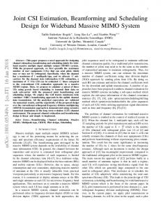
2, 4
Figure 3: Sum rate versus SNR using the proposed hybrid beamforming when 𝐾 = 2, 4 and 𝑁𝑡 = 512.
28 26
Sum rate (Gbps)
24 22 20 18 16 14 12 −30
−25
Full digital Proposed hybrid
−20 SNR (dB)
−15
−10
Existing OMP + BD hybrid Analog
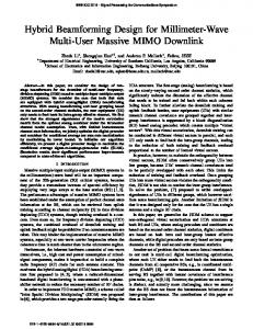
Figure 2: Sum rates versus SNR using the proposed hybrid beamforming, full digital beamforming, analog beamforming, and existing OMP + BD hybrid beamforming algorithms when 𝐾 = 2 and 𝑁𝑡 = 512.
First, we compare the sum rates of different algorithms when 𝐾 = 2 and 𝑁𝑡 = 512 in Figure 2, where we consider the system model in Section 2. The rate achieved by the proposed hybrid beamforming algorithm is compared with the full digital beamforming, analog beamforming, and existing OMP + BD hybrid beamforming algorithm [14, 27]. To evaluate the proposed hybrid beamforming algorithm, we assume azimuth and elevation angles of the phase shifters at the BS to be quantized with 𝑀𝜑 = 20 and 𝑀𝜃 = 20. As can be seen from Figure 2, as expected the rate achieved by the proposed hybrid beamforming is higher than that of the analog beamforming, and superior performance is achieved by the digital beamforming approach. Meanwhile,
the performance of hybrid beamforming is very close to the digital beamforming from the low to moderate SNR regions, and small performance gap is observed at SNR regions within −22∼−10 dB. When SNR increases to more than −10 dB, the proposed hybrid beamforming algorithm will achieve the same saturation value as digital beamforming. And the proposed hybrid beamforming yields a large improvement over the existing OMP + BD hybrid beamforming. Secondly, we examine and compare the performance of the proposed hybrid beamforming with different number of scheduled users per block. We set the same number of transmit antennas in Figure 2 as 𝑁𝑡 = 512 and vary maximum number of scheduled users in different blocks as 𝐾 = 2, 4. As can be seen from Figure 3, increasing the number of MUMIMO users multiplexing in each block can improve the sum rate (for SNR values) due to canceling the residual multiuser interference. The sum rate with 𝐾 = 4 has risen sharply at SNR = −30∼−14 dB. When the value of SNR approaches to −12 dB, it approximately tends to be maximum value and then starts to level off as SNR exceeds −12 dB, while the sum rate with 𝐾 = 2 will also achieve the same maximum value as the value of SNR exceeds −10 dB. Finally, we discuss the performance of hybrid beamforming with different number of transmit antennas. The sum rate is achieved by the hybrid beamforming with 𝑁𝑡 = 128, 256, 512 antennas with 𝐾 = 4. The SNR ranges from −30 dB to −10 dB. It can be found in Figure 4 that as the number of transmit antennas increases, the performance of system enhances significantly from the low to moderate SNR regions. When the SNR approaches to −12 dB, the sum rate with 𝑁𝑡 = 512 approximately tends to be stable. And it saturates after a certain SNR which is around −12 dB. As the value of SNR continues to increase, the sum rate of other cases will also achieve the same maximum value.
International Journal of Antennas and Propagation
9
References
28 26
[1] W. Roh, J.-Y. Seol, J. Park et al., “Millimeter-wave beamforming as an enabling technology for 5G cellular communications: theoretical feasibility and prototype results,” IEEE Communications Magazine, vol. 52, no. 2, pp. 106–113, 2014.
Sum rate (Gbps)
24 22
[2] Y. Niu, Y. Li, D. Jin, L. Su, and A. V. Vasilakos, “A survey of millimeter wave communications (mmWave) for 5G: opportunities and challenges,” Wireless Networks, vol. 21, no. 8, pp. 2657–2676, 2015.
20 18
[3] ITU, “Assessment of the global mobile broadband deployments and forecasts for international mobile telecommunications,” Tech. Rep. ITU-R M. 2243-0, 2011.
16 14 12 −30
−25
−20 SNR (dB)
−15
−10
Proposed hybrid (Nt = 128) Proposed hybrid (Nt = 256) Proposed hybrid (Nt = 512)
[4] T. E. Bogale and L. B. Le, “Massive MIMO and mmWave for 5G wireless HetNet: potential benefits and challenges,” IEEE Vehicular Technology Magazine, vol. 11, no. 1, pp. 64–75, 2016. [5] T. S. Rappaport, S. Sun, R. Mayzus et al., “Millimeter wave mobile communications for 5G cellular: it will work!,” IEEE Access, vol. 1, no. 1, pp. 335–349, 2013.
Figure 4: Sum rates versus SNR using the proposed hybrid beamforming algorithms when 𝐾 = 4 and 𝑁𝑡 = 128, 256, 512.
[6] P. Phunchongharn, E. Hossain, L. B. Le, and S. Camorlinga, “Robust scheduling and power control for vertical spectrum sharing in STDMA wireless networks,” IEEE Transactions on Wireless Communications, vol. 11, no. 5, pp. 1850–1860, 2012.
7. Conclusions
[7] O. Somarriba and J. Zander, “Robust STDMA scheduling in Multi-hop Wireless Networks for single-node position perturbations,” in Proceedings of the IEEE 20th International Symposium on Personal, Indoor and Mobile Radio Communications, pp. 566–571, Tokyo, Japan, September 2009.
In this paper, we propose a joint user scheduling and MU-MIMO hybrid beamforming algorithm for mmWave FDMA massive MU-MIMO system. The users with the same strongest beams direction form an OFDMA user group. For the same OFDMA user group, BS allocates the corresponding frequency resources to the member with the best channel gain. Then, to maximize the mmWave system throughput, MU-MIMO users are selected from OFDMA user groups and other users to be scheduled. For the proposed hybrid beamforming, the analog beamforming vectors apply the optimal beam of each MU-MIMO user. The digital beamforming algorithm is solved by weight MMSE, which not only achieves the optimal performance for each user, but also mitigates the residual interuser interference. Simulation results show that the performance of hybrid beamforming is very close to the full digital beamforming. Thus hybrid beamforming jointly designing with user scheduling can greatly improve the performance of mmWave OFDMA massive MU-MIMO system. Our further work will focus on reducing the complexity of the proposed hybrid beamforming algorithm and increasing the function of adaptive power allocation.
[10] M. Ergen, S. Coleri, and P. Varaiya, “Qos aware adaptive resource allocation techniques for fair scheduling in OFDMA based broadband wireless access systems,” IEEE Transactions on Broadcasting, vol. 49, no. 4, pp. 362–370, 2003.
Competing Interests
[13] L. Liang, W. Xu, and X. Dong, “Low-complexity hybrid precoding in massive multiuser MIMO systems,” IEEE Wireless Communications Letters, vol. 3, no. 6, pp. 653–656, 2014.
The authors declare that there is no conflict of interests regarding the publication of this paper.
Acknowledgments This paper is sponsored by National 863 Project (2014AA01A705).
[8] C. Li, R. Cai, and D. Liu, “A suboptimal STDMA scheduling for concurrent transmissions in mmWave wireless networks,” in Proceedings of the IEEE International Conference on Signal Processing, Communications and Computing (ICSPCC ’14), pp. 137–141, Guilin, China, August 2014. [9] G. Li and H. Liu, “Resource allocation for OFDMA relay networks with fairness constraints,” IEEE Journal on Selected Areas in Communications, vol. 24, no. 11, pp. 2061–2068, 2006.
[11] T. E. Bogale, L. B. Le, and A. Haghighat, “User scheduling for massive MIMO OFDMA systems with hybrid analog-digital beamforming,” in Proceedings of the IEEE International Conference on Communications (ICC ’15), pp. 1757–1762, London, UK, June 2015. [12] D. E. Berraki, S. M. D. Armour, and A. R. Nix, “Codebook based beamforming and multiuser scheduling scheme for mmWave outdoor cellular systems in the 28, 38 and 60GHz bands,” in Proceedings of the IEEE Globecom Workshops (GC Wkshps ’14), pp. 382–387, Austin, Tex, USA, December 2014.
[14] T. E. Bogale and L. B. Le, “Beamforming for multiuser massive MIMO systems: digital versus hybrid analog-digital,” in Proceedings of the IEEE Global Communications Conference (GLOBECOM ’14), pp. 4066–4071, Austin, Tex, USA, December 2014. [15] A. Alkhateeb, R. W. Heath, and G. Leus, “Achievable rates of multi-user millimeter wave systems with hybrid precoding,” in
10
[16]
[17]
[18]
[19]
[20]
[21]
[22]
[23]
[24]
[25]
[26]
[27]
International Journal of Antennas and Propagation Proceedings of the IEEE International Conference on Communication Workshop (ICCW ’15), pp. 1232–1237, IEEE, London, UK, June 2015. W. Ni and X. Dong, “Hybrid block diagonalization for massive multiuser MIMO systems,” IEEE Transactions on Communications, vol. 64, no. 1, pp. 201–211, 2016. E. Jorswieck, B. Ottersten, A. Sezgin, and A. Paulraj, “Feedback reduction in uplink MIMO OFDM systems by chunk optimization,” in Proceedings of the IEEE International Conference on Communications (ICC ’08), pp. 4348–4352, Beijing, China, May 2008. M. A. Ali, S. Al-Ghadhban, and A. S. H. Mahmoud, “Resource allocation scheme for MIMO-OFDMA systems with proportional fairness constraints,” in Proceedings of the IEEE 8th International Conference on Wireless and Mobile Computing, Networking and Communications (WiMob ’12), pp. 512–516, Barcelona, Spain, October 2012. O. E. Ayach, R. W. Heath, S. Abu-Surra, S. Rajagopal, and Z. Pi, “Low complexity precoding for large millimeter wave MIMO systems,” in Proceedings of the IEEE International Conference on Communications (ICC ’12), pp. 3724–3729, Ottawa, Canada, June 2012. T. E. Bogale, L. B. Le, A. Haghighat, and L. Vandendorpe, “On the number of RF chains and phase shifters, and scheduling design with hybrid analog-digital beamforming,” IEEE Transactions on Wireless Communications, vol. 15, no. 5, pp. 3311–3326, 2016. Z. Li, P. Li, and K. G. Shin, “MU-MIMO downlink scheduling based on users’ correlation and fairness,” in Proceedings of the 25th IEEE Annual International Symposium on Personal, Indoor, and Mobile Radio Communication (PIMRC ’14), pp. 407–412, Washington, DC, USA, September 2014. M. Stojnic, H. Vikalo, and B. Hassibi, “Rate maximization in multi-antenna broadcast channels with linear preprocessing,” IEEE Transactions on Wireless Communications, vol. 5, no. 9, pp. 2338–2342, 2006. T. E. Bogale and L. B. Le, “Pilot optimization and channel estimation for multiuser massive MIMO systems,” in Proceedings of the 48th Annual Conference on Information Sciences and Systems (CISS ’14), Princeton, NJ, USA, March 2014. Q. Shi, M. Razaviyayn, Z.-Q. Luo, and C. He, “An iteratively weighted MMSE approach to distributed sum-utility maximization for a MIMO interfering broadcast channel,” IEEE Transactions on Signal Processing, vol. 59, no. 9, pp. 4331–4340, 2011. L. C. Pansana, Transmit-Receive Beamforming for 60 GHz Indoor Wireless Communications, Aalto University School of Science and Technology, Espoo, Finland, 2010. A. Maltsev, V. Erceg, E. Perahia et al., Channel models for 60 GHz WLAN systems, IEEE Document 802.11-09/0334r8, May 2010, https://mentor.ieee.org/802.11/dcn/09/11-09-033408-00ad-channelmodels-for-60-ghz-wlan-systems.doc. O. E. Ayach, S. Rajagopal, S. Abu-Surra, Z. Pi, and R. W. Heath, “Spatially sparse precoding in millimeter wave MIMO systems,” IEEE Transactions on Wireless Communications, vol. 13, no. 3, pp. 1499–1513, 2014.
International Journal of
Rotating Machinery
Engineering Journal of
Hindawi Publishing Corporation http://www.hindawi.com
Volume 2014
The Scientific World Journal Hindawi Publishing Corporation http://www.hindawi.com
Volume 2014
International Journal of
Distributed Sensor Networks
Journal of
Sensors Hindawi Publishing Corporation http://www.hindawi.com
Volume 2014
Hindawi Publishing Corporation http://www.hindawi.com
Volume 2014
Hindawi Publishing Corporation http://www.hindawi.com
Volume 2014
Journal of
Control Science and Engineering
Advances in
Civil Engineering Hindawi Publishing Corporation http://www.hindawi.com
Hindawi Publishing Corporation http://www.hindawi.com
Volume 2014
Volume 2014
Submit your manuscripts at http://www.hindawi.com Journal of
Journal of
Electrical and Computer Engineering
Robotics Hindawi Publishing Corporation http://www.hindawi.com
Hindawi Publishing Corporation http://www.hindawi.com
Volume 2014
Volume 2014
VLSI Design Advances in OptoElectronics
International Journal of
Navigation and Observation Hindawi Publishing Corporation http://www.hindawi.com
Volume 2014
Hindawi Publishing Corporation http://www.hindawi.com
Hindawi Publishing Corporation http://www.hindawi.com
Chemical Engineering Hindawi Publishing Corporation http://www.hindawi.com
Volume 2014
Volume 2014
Active and Passive Electronic Components
Antennas and Propagation Hindawi Publishing Corporation http://www.hindawi.com
Aerospace Engineering
Hindawi Publishing Corporation http://www.hindawi.com
Volume 2014
Hindawi Publishing Corporation http://www.hindawi.com
Volume 2014
Volume 2014
International Journal of
International Journal of
International Journal of
Modelling & Simulation in Engineering
Volume 2014
Hindawi Publishing Corporation http://www.hindawi.com
Volume 2014
Shock and Vibration Hindawi Publishing Corporation http://www.hindawi.com
Volume 2014
Advances in
Acoustics and Vibration Hindawi Publishing Corporation http://www.hindawi.com
Volume 2014