Joystick mapped Augmented Reality Cues for End-Effector controlled Teleoperated Robots Aditya Nawab 1,Keshav Chintamani1, Darin Ellis2, Gregory Auner, Abhilash Pandya 1* 1
Wayne State University:, Electrical and Computer Engineering Department (*
[email protected]) 2 Wayne State University, Industrial Engineering Department
ABSTRACT End-effector control of robots using just remote camera views is difficult due to lack of perceived correspondence between the joysticks and the end-effector coordinate frame. This paper reports the positive effects of Augmented Reality visual cues on operator performance during end-effector controlled teleoperation using only camera views. Our solution is to overlay a color-coded coordinate system on the end-effector of the robot using AR techniques. This mapped and color-coded coordinate system is then directly mapped to similarly color-coded joysticks used for control of both position and orientation. The AR view along with mapped markings on the joystick give the user a clear notion of the effect of their joystick movements on the endeffector of the robot. All camera views display this registered dynamic overlay information on-demand. A preliminary test using fifteen subjects comparing control of performance with and without the coordinate mapping was performed by using a simple insertion task. Preliminary results indicate a significant reduction in distance, reversal errors and mental workload. CR Categories: Human Factors, Information Presentation, User Interaction Keywords: Robotics, Augmented Reality, Tele-operations, Kinematics, Performance Testing. 1 INTRODUCTION Operating a robotic arm from indirect visual information poses many technical and human performance challenges for the operator. Due to the sometimes-oblique camera viewpoints, the tele-operator can get disoriented with respect to coordinate systems. For instance, left-right may be reversed from a particular camera view. Thus the tele-operator must mentally transform (i.e. rotate, translate and scale) the desired motion of the robot to determine the required input at the joystick, a task often mentally challenging and tiresome. These transformations are especially demanding with interfaces that involve multiple cameras and displays, as the operator must relearn them whenever he switches views [1] [5]. Lighting conditions (harsh shadows and camera blooms) and poor camera angles can sometime provide degraded images of the operation site and hinder successful operations. Previous work in the field of Augmented Reality have been addressed to solve the issues of time delay by implementing predictive display techniques and similar AR techniques for path planning which allows the user to move the robot along a planned path that was generated by manipulating the AR model of the robot in the live video view [12] [13]. However, these studies do not resolve the challenges faced in navigating the end effector of the robot during teleoperation using non-orthogonal camera views. The aim of this project is to instrument NASA’s Special Purpose Dexterous Manipulator (SPDM) cameras with Augmented Reality to assist the astronaut navigate the robot by making the cognitive
transformations inherent in teleoperation less mentally taxing. More specifically, we have focused on the demanding ‘Orbital Replacement Unit (ORU) insertion’ task which requires the operator to place an ORU into a receptacle on the International Space Station using the SPDM. Since the ORU is grasped by the end-effector, the end effector camera view gets obstructed. This makes it difficult for the tele-operator to navigate the robot. Current research and development activities by this team have led to the development of two prototypes for AR-enhanced robotic operations. There have been two separate and independent approaches used (1) based on image processing and edge detection and (2) based on kinematic measurements of the robotic device. The algorithm will use accurate real-time kinematics data (joint angles) from the robot to render Augmented Reality cues to the astronauts. Since this approach is dependent on the robot kinematics and the range of motion of each of the joints and their accuracy, this method will not fail under poor lighting conditions. Work related to AR implementation based on image processing and edge detection can be found in [3]. 2 METHODS In this section, the methodology to be used for robotic test-bed development, AR software development and integration, testing and human factors testing and evaluation is described. First the development of the robotic test-bed system will be discussed, then a section on the AR software development will be presented, along with a section on the Human Factors methods that will be used. 2.1. Robotic Test-bed Development The simulators at the Johnson Space Center are used frequently for operational task planning and training and it is often difficult to get an adequate amount of time for advanced research and development activities. For this purpose, a low-cost robotic system has been developed at Wayne State University for design and testing of advanced features.
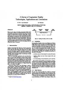
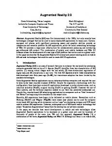
Figure 1: Left: User controlling the NASA robot with two handcontrollers and remote video views. Right: The Wayne State University test bed.
This robotic test-bed provides a platform for development and implementation of several advanced features that will be investigated. The test-bed consists of a six degree of freedom robotic arm, two joysticks to control the translational and rotational motion of the robot, three cameras and a network server to transmit video from the three cameras over the internet. The software design of the robot is client/server based. As a result, the robotic system can be controlled from anywhere over the internet. In this section, the development of the inverse kinematics algorithm will be discussed, followed by a description of the robotic test-bed with the transformations involved between the various components of the test-bed.
2.1.1. Inverse Kinematics Algorithm Inverse kinematics algorithm for this robot was derived using a closed loop spherical mechanism. In this method, the end-effector is joined to the ground by a hypothetical link. The six parameters that specify the position and orientation of the end-effector can easily be transformed into the corresponding closed-loop spatial mechanism, that is, the computation of multiple solution sets of the joint variables of the closed-loop spatial mechanism. In the closed-form approach, all the possible sets of joint parameters that locate the robot’s end-effector as desired will be found by firstly solving a polynomial in the tan-half-angle of one of the joint variables. Admittedly it is necessary to iterate to solve for the roots of a polynomial of degree greater than four [2]. In the particular case of our robot, the geometry of the robot (perpendicular, intersection and parallel joint axes) simplified the reverse analysis. Since the degree of polynomial derived was less than three, the closed loop algorithm became a non-iterative direct solution. Hence the computational time to calculate the joint angles was reduced considerably. The inverse kinematics solution is robust, highly accurate and was verified by computing the inverse kinematics solution for a full-range of known pose and angle pairs.
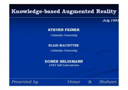
TCE = TCR x TBR-1 x TBE
(1)
TCE = ? TC
TE
TCR
TBE
TR TBR
Camera
TB
Base
Receptacle
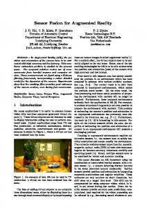
Joystick Figure 2: Transformations between various components of the robotic system.
Using the intrinsic parameters of a particular camera and the transformation TCE, the coordinate system at the end-effector can be projected onto the image plane [6]. The joystick axes are color coded such that they map directly to the coordinate axes augmented at the end-effector of the robotic manipulator in all the camera views. The color codes for the rotational and translational joysticks on the joysticks itself are identical to each other.
2.1.2. Description of Robotic Test-bed The robot is remotely controlled by a user with two joysticks. Three non-orthogonal video views are available to the user to navigate around the workspace. The video views are available through the network server at 30 frames per second. Figure 2 shows the transformations between the various components of the robotic test-bed. These transformations will be used to determine the transformation (TCE) between the camera frame TC and endeffector frame TE. The transformation TCE will then be used to overlay the coordinate systems. As shown in Figure 2, TC, TB, TE, and TR refer to the camera, robot base, end-effector and receptacle (i.e., the target) coordinate frames respectively. TBE, which is the transformation between the base and the end-effector, is derived by applying a forward transformation using the real time kinematics data from the robot. TCR, which is the transformation between the camera and the receptacle, is derived by performing a pair-point registration between the camera and the receptacle [7]. TBR is the transformation between the robot base and the receptacle. This transformation is derived by inserting the simulated orbital replacement unit (ORU) in the receptacle and applying a forward transformation using the real time kinematics data from the robot. The transformation between the camera and the end-effector TCE is now derived by applying the following transformation:
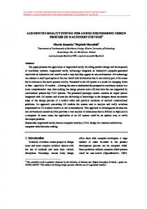
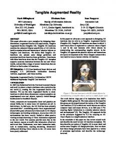
Figure 3: Left: Snapshots from one of the three camera views with augmented coordinate system. Right: Color coded joystick mapped to end-effector coordinate frame
The direction of the coordinate axes in the augmented views is used for translational cues. For example, in Figure 3, moving the translational joystick along the green direction on the joystick will move the ORU along the green axes in all the camera views. The axes on which the color coded spheres are augmented reflect the axes of rotation. For example, in Figure 3, moving the rotational joystick along the green direction on the joystick will rotate the ORU keeping the green sphere constant in all the views ( the rotation axes will be the axes on which the green sphere is attached). Also, the radius of the spheres indicate the proximity of
2.2. Software Development The software design for the AR is client/server based. In this design, an Augmented Reality client executes on the primary computer and data for the augmentation is sent to the client via the socket interface from hardware (robot and video server) specific servers. The advantage of this design is that multiple clients can view the augmentation from any location, the software will be modular and execution can be very fast as this is a distributed and multi-processor environment. In addition, the AR client in a multi camera system, provided with the appropriate camera information, can easily display relevant information for each of the cameras in the system. The robotic system will serve as a server providing the AR clients with the real time kinematics data of the robot. The “a priori” knowledge of the geometry of the ORU and the receptacle, combined with the real time kinematics data and the intrinsic and extrinsic parameters of the camera, will be used to accurately overlay the coordinate system on all the camera views. Based on the same information, another coordinate system will be overlaid at the receptacle on all the camera views. Aligning the two coordinate systems at the end-effector and the receptacle in all the camera views will assist the operator in ensuring an accurate ORU insertion operation. 3 HUMAN FACTORS PILOT TEST A rigorous series of operator-in-the-loop tests are planned to validate our AR system. These tests would be based on previous successful Human Factors studies that have been conducted by the group [8], [9], [10] and [11]. However, a pilot set of data (15 subjects) has been taken which provides a promising, albeit initial, set of results. The tasks chosen for testing includes orbital replacement unit tasks that involve accurate alignment and manipulation of the robot arm. Tasks were selected to be representative of on-orbit tasks such as alignment for ORU insertion into the worksite receptacle. A between group subject design was used for comparison. Each subject had either with AR or no AR condition to avoid training effect. Time pressure was introduced by having a time based test. The performance of operating the system with these two conditions was evaluated by obtaining distance and error data while performing object insertion tasks.
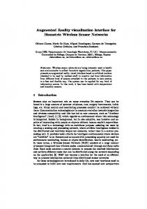
subject belonged to, thirty minutes of training with AR or without AR was provided. The independent variables are type of operation (AR, No AR) and starting position (P1). The starting position P1 was chosen such that the end-effector pointed away from the receptacle and was completely visible in one of the camera views. Previous experiments conducted by our group gave us a reasonable estimate of the time required to complete the task [5]. The straight line distance from the receptacle was about forty three inches. Three non-orthogonal views of the test bed were provided. Two cameras provided non-orthogonal close up views of the receptacle, where as the third camera gave a bird’s eye view of the robot. The robot was initialized to a start position and the participant was asked to start the test. Stop clock set for five minutes was started. When the participant completely inserted the payload, the time remaining was noted. Three trials were provided for the condition and subjects were asked to minimize distance and errors while completing the insertion task before the clock ran out. Distance traveled and reversal error data was collected. We plan to continue this trend to evaluate a minimum of twelve other subjects. 3.2. Preliminary Results One of the key indications of performance degradation is the number of joystick reversals. The user intended to go in one direction, making the wrong input on the joystick and reversing his decision. Reversal errors are counted if the subject moves away from the worksite. Preliminary results have shown a considerable increase in user performance in terms of number of reversal errors. As shown in Figure 4, the numbers of reversal errors have reduced (17 with AR and 37 without AR) and are statistically significant (p < = 0.002) which indicate that the user is not disoriented with respect to the coordinate systems and has a better understanding of navigating the robot in the right direction. Reversals as a Function of AR Use 60 50
Distance (in)
each coordinate axes to the image plane. The sphere closest to the image plane will have the maximum radius. A worksite coordinate system is augmented on the receptacle, which aids the tele-operator to align the ORU before insertion. The coordinate system overlays would be available on all the camera views.
40 30 20 10 0 AR
NO AR AR vs. No AR
3.1. Human Factors Method An end user human factors evaluation was performed to assess the effects of AR on user performance. Fifteen participants (11 males and 4 females, 8 without AR and 7 with AR, aged between 20 and 35) were asked to control the end-effector of the robot from a preselected starting position (P1) and insert the attached payload into a receptacle placed on an optical table at the base of the robot. The participants were given five minutes per trial to complete the insertion task. There was a mix of expertise within the subjects with respect to robot use and general gaming experience with joysticks. The participants were randomly chosen to perform the tasks with or without AR. Depending on the group in which the
Figure 4: Reversal Errors as a Function of AR Use
As expected, the distance traveled to the target with AR reduced considerably (98.6 inches with AR and 138.23 inches without AR) and showed statistical significance as well (p