k + -buffer: Fragment Synchronized k-buffer Ioannis Fudos † Dept. of Computer Science & Engineering University of Ioannina
Andreas A. Vasilakis ∗ Dept. of Computer Science & Engineering University of Ioannina
B
(a)
AUB
A-B
A
A∩B
(b)
(c)
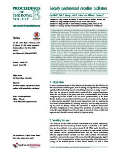
Figure 1: A large repertoire of multi-fragment effects can be supported from our framework: (a) Illustrating order-independent transparency of an engine consisting of 195 random-painted components. (b) Rendering boolean operations between a head (model A) and a clipped sphere (model B) surfaces. (c) Detecting collision (highlighted with red color) between a twirl object moving towards a static clipped sphere.
Abstract k-buffer facilitates novel approaches to multi-fragment rendering and visualization for developing interactive applications on the GPU. Various alternatives have been proposed to alleviate its memory hazards and to avoid completely or partially the necessity of geometry pre-sorting. However, that came with the burden of excessive memory allocation and depth precision artifacts. We introduce k+ -buffer, a fast and accurate framework that simulates the k-buffer behavior by exploiting fragment culling and pixel synchronization. Two GPU-accelerated data structures have been developed: (i) the maxarray and (ii) the max-heap. These memory-bounded data structures accurately maintain the k-foremost fragments per pixel in a single geometry pass. The choice of the data structure depends on the size k (application-dependent). Without any software-redesign, the proposed scheme can be adapted to perform as a Z-buffer or an Abuffer capturing a single or all generated fragments, respectively. A memory-friendly strategy is also proposed, extending the proposed pipeline to dynamically lessen the potential wasteful memory allocation. Finally, an extensive experimental evaluation is provided demonstrating the advantages of k+ -buffer over all prior k-buffer variants in terms of memory usage, performance cost and image quality. CR Categories: I.3.6 [Computer Graphics]: Methodology and Techniques—Graphics data structures and data types Keywords: GPU, k-buffer, a-buffer, max-heap, multi-fragment effects, real-time, pixel synchronization
1
Introduction
Determining visibility when rasterizing objects in arbitrary order is a challenging task in terms of time and space for a host of algorithms that simulate complex rendering effects in realtime. Many image-based techniques produce visually realistic ∗ e-mail:
[email protected] † e-mail:
[email protected]
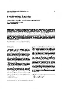
results at interactive speeds in games (order-independent transparency [Maule et al. 2011], shadows [Yang et al. 2010], hair rendering [Yu et al. 2012]) and other graphics applications (volume rendering [Callahan et al. 2005], collision detection [Jang and Han 2008], constructive solid geometry [Rossignac et al. 2013]) enabled by a family of GPU-accelerated methods that capture the surfaceintersections (fragments) when ray casting from the viewer position through each screen pixel. Figure 2 shows an illustrative example of the fragment generation process through per-pixel ray-surface intersection tests. Buffer-based techniques ensure the correct visibility order on the level of fragments, avoiding drawbacks (e.g. geometry interpenetration, primitive splitting, dynamic scenes) that occur in object/primitive sorting techniques [Govindaraju et al. 2005; Sintorn and Assarsson 2008]. Extending Z-buffer, where the closest-to-viewer fragment is stored, A-buffer [Carpenter 1984] was the first method to capture all fragments per pixel in a single geometry pass. Fragments are stored into variable-length linked lists per pixel during geometry rendering, followed by a post-sorting process that correctly reorders fragments by their depth. Several variants and optimizations [Maule et al. 2011] have been proposed recently to simulate the behavior of the A-buffer architecture with reduced memory requirements generating more or less approximate image outputs. k-buffer [Bavoil et al. 2007] employed per-pixel fixed-size vectors maintaining a k-nearly sorted sequence of fragments in bounded GPU memory. When the number of generated fragments exceeds k, the rasterization order of the generated fragments affects the final result due to memory read-modify-write (RMW) hazards. Heuristics (primitive pre-sorting and triangle batches) may alleviate most of the image quality flaws with the burden of higher computational cost. A number of GPU-accelerated k-buffer variants have been recently introduced that avoid RMW hazards and geometry ordering prior to rasterization by either initially building an A-buffer [Yu et al. 2012] or exploring a two-geometry-pass scheme based on atomic memory operations [Liu et al. 2010; Maule et al. 2013]. However, a significant increase of unbounded memory is required when A-buffer is used as temporary storage. On the other hand, atomic operations are restricted to only work on 32-bit unsigned integer format resulting in (i) visual artifacts from lost precision when converting depth values and (ii) performance cost of an additional geometry pass. We introduce k+ -buffer (K+ B), a single-geometry-pass k-buffer framework that overcomes the aforementioned performance bottlenecks, memory footprints and rasterization artifacts. Inspired by [Crassin 2010b], a semaphore-based spin-lock mechanism ensures atomicity of the per-pixel fragment operations at the shared memory. Implementation details are also provided to easily switch to the hardware-implemented pixel syncing solution available on the
Updated version of the final, definitive version of this paper, available at: http://dl.acm.org/citation.cfm?id=2556702
Haswell architecture [Salvi 2013]. To alleviate contention (busywaiting) of distant fragments, we concurrently perform culling checks that efficiently discard fragments that are further from all currently maintained fragments. Two array-based data structures are built on the GPU to accurately store the closest per-pixel fragments: (i) max-array, an array where the maximum element is always stored at the first entry and (ii) max-heap, a complete binary tree in which the value of each internal node is greater than or equal to the values of the children of that node. Despite its linear complexity, the former performs faster than the latter when the problem size is sufficiently small. For example, order-independent transparency presents high approximation images even with a small core of captured layers (k ≤ 16). Conversely, plausible photorealistic appearance of hair requires the contribution of a larger set of hair strands (k > 16). To avoid the wasteful pre-allocated storage requirements of pixels that contain less than k fragments (k-fragmentless pixels, see Figure 2), we have extended our framework by the S-buffer pipeline [Vasilakis and Fudos 2012]. An additional geometry pass is performed for counting fragments per pixel, enabling us to allocate the exact amount of memory that we actually need. Memory is linearly organized into variable contiguous regions for each pixel, making it feasible to implement both proposed data structures. To our knowledge, this is the first k-buffer implementation with dynamic and precise allocation of the required storage space. Without any adaptation, our framework can also support the functionalities of the Z-buffer and A-buffer by setting k to either one or large enough to handle all possible per-pixel fragment cardinalities. The structure of this paper is as follows: Section 2 offers a brief overview of prior art. Section 3 introduces the algorithmic details of our k+ -buffer framework. Section 4 provides extensive comparative results for several of multi-fragment rendering alternatives. Finally, Section 5 offers conclusions and identifies future research directions. z0
z1
z3
z1
x
x
z0
z2
view direction
sorting
z0
x
z1
x
z2
x
z3
x
Figure 2: Illustrating the construction process of a row of a 4-buffer (highlighted with blue at the top-right thumbnail), when ray casting the dragon model. A significant amount of memory space is wasted at pixels that consist of less than 4 fragments due to the pre-allocation of the same buffer length per pixel.
2
Related Work
There is an abundance of recent research on treating the problem of storing multiple fragments from different perspectives. Abuffer [Carpenter 1984] exploited an unbounded buffer for building dynamically created per pixel lists of all fragments in submission order using a single rendering pass. Then, stored fragments are postsorted according to their depth values. An actual GPU-accelerated implementation of A-buffer based on atomic memory operations was recently introduced in [Yang et al. 2010] (LL). However, its performance degrades rapidly due to the heavy contention and the
random memory accesses when constructing and assembling the entire fragment list, respectively. A memory-friendly variation of this algorithm was described in [Crassin 2010b], where paged per-pixel linked-lists (LL-Paged) improve caching and data bus occupancy. On the other hand, [Vasilakis and Fudos 2013] improved performance by concurrently storing fragments into more than one per-pixel linked lists. They have proposed to uniformly split the depth range of the rasterized scene (see also [Liu et al. 2009b; Sintorn and Assarsson 2009]) and assign one linked list in each subdivision. FreePipe [Liu et al. 2010], a complete CUDA-based rasterization pipeline, maintains multiple fragments using constant-size per pixel vectors. To ensure complete fragment extraction for all pixels, the buffer length must be set accurately. FreePipe has been realized using modern OpenGL APIs [Crassin 2010a], thus avoiding switching from the traditional graphics pipeline to a software rasterizer. Despite its high computation speed, FreePipe suffers from large and potentially unnecessary memory consumption. Last but not least, S-buffer (SB) [Vasilakis and Fudos 2012], a two-geometry-passes A-buffer implementation on the GPU, has overcome the limitations of both linked-lists and fixed-array techniques by taking advantage of the fragment distribution and the sparsity of the pixel-space. Regardless of the data structure, the aforementioned approaches suffer from (i) memory overflows resulted from the unbounded buffer needed to store all generated fragments, and (ii) performance bottlenecks arise when the number of per-pixel fragments to be postsorted increases significantly. To this end, k-buffer (KB) [Callahan et al. 2005; Bavoil et al. 2007] reduced memory requirements capturing the k-closest to the viewer fragments in a single geometry rasterization. However, it is susceptible to disturbing flickering artifacts caused from RMW hazards during fragment insertion updates. [Liu et al. 2009a] extended this work to a multi-pass approach (KBMulti) achieving robust rendering behavior with the trade-off of low frame rates. Moreover, [Bavoil and Myers 2008] eliminated most of the memory conflicts by performing stencil routing operations on a multi-sample anti-aliasing buffer (KB-SR). Finally, [Zhang 2013] explored a memory-hazard-aware solution (KB-MHA) based on a depth-error correction coding scheme. In practice however, they cannot guarantee correct results in all cases. The image quality of this class of methods is highly dependent on a coarse CPU-based pre-sorting in primitive-space which eliminates the arrival of out-oforder fragments. Multiple rendering iterations, are further required to provide an A-buffer output, due to the limited number of multiple render targets on the GPU. This results in significant performance downgrade. Conversely, [Wang and Xie 2013] proposes partitioning the input scene into components with a few layers and then rendering them individually in order to fit into the limited KB-SR buffer size. However, this comes with the burden of non-supporting animated scenes and having limited order-dependent applicability. Multi depth test scheme (KB-MDT), developed in both CUDA [Liu et al. 2010] and OpenGL [Maule et al. 2013] APIs, guarantees correct depth order results by capturing and sorting fragments on the fly via 32-bit atomic integer comparisons. Since 64-bit atomic operations are not supported from available APIs to update the depth and color buffers simultaneously, a costly additional geometry pass is therefore suggested. Furthermore, noisy images may be generated due to the precision lost when converting floating depth values of close fragments. Similar to our method, [Salvi 2013] extended the original kbuffer to avoid fragment racing by employing hardware-aware pixel synchronization (KB-PS). However, this method is currently compatible only with graphics cards based on the Haswell architecture. Finally, [Yu et al. 2012] proposed two linked-list-aware solutions to accurately compute the k-foremost fragments. The idea of the first one is to capture all fragments by initially constructing A-buffer by the method of [Yang et al. 2010], followed by a step that selects and sorts the k-nearest fragments (KB-ABLL ). On the other hand, the second approach directly computes depth-ordered per-pixel linked lists avoiding the unnecessary A-buffer construction (KB-LL). Despite the fact that the second approach requires less storage, fragments are sparsely stored in graphics memory causing the additional allocation of contiguous blocks of memory.
Table 1 presents a comparative overview of all k-buffer alternatives with respect to memory requirements, rendering complexity, fragment extraction accuracy and sorting necessity.
3
Framework Overview
We propose an efficient k-buffer implementation on the GPU which is free from: (i) geometry sorting prior rasterization, (ii) unbounded memory necessity, (iii) RMW memory-hazards and (iv) depth precision conversion artifacts. Contrary to most of the aforementioned k-buffer alternatives which store and sort the generated fragments on the fly, we follow a faster strategy similar to the one used by the A-buffer construction: The k-nearest fragments are captured in an unsorted sequence, followed by a post-sorting step that reorders them by their depth. We explore a GPU-accelerated spin-lock strategy via pixel semaphores to ensure real-time synchronized construction of the unsorted k-front fragments (Section 3.1). Two bounded array-based data structures for fragment data are introduced which enable a low cost culling test that concurrently discards outlier fragments (Section 3.2). A pipeline extension is further introduced to dynamically and precisely handle graphics memory allocation (Section 3.3). k+ -buffer can also be considered as an unified framework that successfully integrates the functionalities of Z-buffer, k-buffer and A-buffer (Section 3.4). The overall framework is described by offering shader-like pseudocode and the fragment processing pipeline. Finally, we highlight features and tradeoffs of our framework, pointing out implementation details and light-weight modifications that can be used to guide the decision of which pipeline alternative to employ in a given setting.
3.1
Spin-lock Strategy
Per-pixel binary semaphores are utilized as a synchronization mechanism to ensure fragment exclusive use of the critical storage section. Taking into account the possibility of simultaneous access to the lock, which could cause race conditions, an implementation of an atomic test-and-set operation is explored. The calling process obtains the lock if the old value was 0. It spins writing 1 to the variable until this occurs. One way to implement spin-lock strategy employing test-and-set into a pixel shader is shown in the Algorithm 1. Algorithm 1 MutualExclusion (Texture t, Pixel p) 1: while true do ⊲ spin until lock is free 2: if imageAtomicExchange(t, p, 1) == 0 then 3: {critical section} ⊲ exclusive use 4: imageStore(t, p, 0); ⊲ release lock when finished 5: discard; ⊲ exit shader 6: end if 7: end while
A 32-bit unsigned integer texture with internal pixel format R 32UI is allocated to represent the per-pixel semaphores. At first, a full-screen rendering (clear pass) is executed to initialize texture with zeros. Our method is enhanced by the OpenGL’s imageAtomicExchange(texture lock, ivec2 P, uint V) function which atomically replaces the value V of the atomic object with the argument into texel at coordinate P and returns its original value. Note that there is no need for an atomic operation to perform the lock release (since the running fragment has exited from the critical section) as opposed to the implementation of [Crassin 2010b] where an additional costly atomic exchange is used. Pixel Synchronization (PS) is a graphics extension that Intel has implemented for 4th Generation Intel Core processors with Iris and Iris Pro graphics based on Haswell architecture. PS provides a performance-wise inexpensive mechanism which avoids fragment conflicts in the critical section and ensures that RMW memory operations are performed in submission order [Salvi 2013]. Our framework can be enhanced by the use of PS without remodeling the proposed pipeline. Implementation-wise, a simple call of beginFragmentShaderOrderingINTEL() function is necessary to provide
fragment serializability. Thus, the per-pixel semaphore-based spin-lock strategy can be omitted (specifically, lines 18-19 and 25-28 in Algorithm 3). Avoiding the usage of per-pixel semaphores also results in reduced memory demand. While DirectX11+ and OpenGL extensions are available for Intel graphics cards, we expect that these will be supported in the near future by all manufacturers.
3.2
Fragment Capturing
A geometry rendering (store pass) is initially carried out to capture the closest fragment data per-pixel in a 64-bit floating point 3D array buffer with internal format of RG 32F, (R for color and G for depth) and k length. Figure 2 illustrates a k+ -buffer which can hold up to 400 fragments (screen size: 10 × 10, k = 4). To alleviate the spinning of n generated fragments that do not belong to the closest k, a fast culling mechanism is performed. The idea is to efficiently discard each incoming fragment fi , ∀i ∈ {0, . . . , n − 1} that has equal or larger depth value (fi .z) from all currently maintained fragments, before trying to acquire the semaphore. Note that i determines the submission order. Let KBi [:] = {KBi [j], j = 0 . . . k − 1} denotes the contents of the k-buffer when fragment fi has been processed. Initially, we don’t discard any incoming fragment until the fragment storage buffer is full (∀i < k). Then, we discard all fragments fi such that fi .z ≥ max{KBi−1 [:].z}. On the other hand, a fragment with fi .z < max{KBi−1 [:].z} replaces the fragment of the KB with the largest depth value. This strategy guarantees that the k-nearest fragments will always survive since: max{KBn−1 [:].z} ≤ · · · ≤ max{KBi−1 [:].z} ≤ · · · ≤ max{KBk−1 [:].z}. Note that this process has no impact at the worst case scenario of fragments arriving in descenting depth order. To achieve fragment culling without traversing the entire pixel row for every incoming fragment, we have developed two array-based data structures on the GPU that both store the maximum element at the first array position: (i) max-array (K+ B-Array) and (ii) max-heap (K+ B-Heap). Thus, this operation is performed in constant time. Figure 3 illustrates how two incoming fragments are successfully discarded using this formula when the buffer is completely full. Max-array can be considered as an array where the fragment with the largest depth value is always stored at the first location and the rest are randomly positioned. When an incoming fragment obtains a semaphore, it stores its information in the first empty entry (O(1)). In this case, a per-pixel counter (32-bit unsigned integer texture with internal pixel format R 32UI) is utilized as index and incremented after a successful insertion. Per-pixel counters are initialized to zero during the clear full-screen rendering pass. If the array is full (counter == k), it takes the place of the fragment with the larger depth value. Note that since culling mechanism resides outside critical section, an additional checking is mandatory to guarantee correct results. To keep max-array consistent after an insertion on a completely filled array, we find the fragment with the largest depth value (O(k)) and swap it with the newly added fragment (except the latter is the largest one). This process is implemented without the use of any costly atomic memory operations since fragment atomicity is guaranteed. However when the problem size increases rapidly (k > 16), fragment data information is maintained in a max-heap data structure. Max-heap is a complete binary tree (shape property) in which all nodes are greater than or equal to each of its children (heap property). Max-heap can be implemented using a simple k-sized array without allocating any space for pointers: If the tree root is at index 0, then each element at index i ∈ [0, k) has children at indices 2i + 1 and 2i + 2 and its parent is located at index ⌊ (i−1) ⌋. Since the 2 first node contains the largest element, the core pipeline followed by max-array is not altered. Both inserting operations to an empty or a full heap modify the heap to conform to the shape property first, by adding nodes from the end of the heap or replacing the heap root (O(1)). Then, the heap property is restored by traversing up-heap or down-heap (O(log2 k)). Pseudocode for both insertion
fragments arrival order
counter > k
counter ≤ k 15
12
Max-Array
20
5
7
10
11
9
25
1
18
Max-Heap 15
1
-
15
-
-
-
-
-
20 2 0
-
-
15
12
20
5
7
10
-
-
15
12
20
5
7
10
11
20
15
12
9
5
7
10
11
15
15
0
10
12
12
15
20 12
15 15
9
7
10
1 0
12 1
9 2
5 3
7 4
10 5
7
10 0
5
7
10
1
3
4
5
6
7
11 6
2
9
5
11 1
15
11
1
11
11 1
15
12 0
11 1
9 2
7 3
10 4
1 5
5 6
7
Figure 3: Overview of the insertion process of an arbitrary sequence of out-of-order fragments when (left) max-array and (right) max-heap data structures with k = 8 are utilized. The incoming fragment in each step is highlighted with a glow effect. When the array is full, fragments with value larger than the maximum captured fragment (yellow-colored) are efficiently discarded (f8 .z= 25 and f10 .z= 18).
functions is shown in Algorithm 2, where P(f ) defines the parent of a fragment f and L(f ) and R(f ) its left and right children. Figure 3 illustrates how both data structures with k = 8 are constructed and updated from a number of out-of-order fragment insertions. A representation comparison between max-array and max-heap node pointers is also shown. Algorithm 2 InsertToHeap (Heap h, Pixel p, Fragment f , Int k) 1: procedure UP - HEAP(h, p, f, k) 2: i := 0; 3: h[p.counter] := f ; 4: while i++ < log2 (k) do 5: if f .z> P(f ).z then 6: swap(f, P(f )); 7: else 8: break; 9: end if 10: end while 11: end procedure
⊲ Add f to the bottom level of h ⊲ Iterate until leaves are reached ⊲ Compare f with its parent ⊲ Swap f with its parent ⊲ Correct depth order, exit
12: procedure DOWN - HEAP(h, f, k) 13: i := 0; 14: h[0] := f ; ⊲ Replace root with f 15: while i++ < log2 (k) do ⊲ Iterate until leaves are reached 16: C(f ) := max{L(f ),R(f )}; ⊲ Find f ’s largest child 17: if f .z< C(f ).z then ⊲ Compare f with its largest child 18: swap(f, C(f )); ⊲ Swap f with its largest child 19: else 20: break; ⊲ Correct depth order, exit 21: end if 22: end while 23: end procedure
Finally, a sorting process is employed to reorder the fragments for each pixel before generating the final image (resolve pass). Unsorted fragments are initially copied into a local array before performing the depth sort, as it is relatively faster to perform read-write operations in the register space rather in the global graphics memory. Based on the number of captured fragments, a mechanism decides which sorting algorithm is applied to the pixel. Despite its quadratic complexity, insertion sort is faster for sorting small fragment sequences (k ≤ 16). When k increases, O(k log k) sorting algorithms, such as shell sort, have better performance [Knowles et al. 2012].
3.3
Precise Memory Allocation
Similar to all k-buffer alternatives where k is the same for all pixels, k+ -buffer suffers from potentially large unused memory space allocation of k-fragmentless pixels. For example, Figure 2 illustrates the wastefully allocated storage of a 4-buffer for (top) a pixel that consists of 2 fragments and (bottom) an empty-pixel. Note that the value of k is not automatically adjusted based on the rasterized scene and must be carefully set a priori by the user.
Inspired by S-buffer [Vasilakis and Fudos 2012], we introduce a memory-aware k+ -buffer implementation using two geometry passes (K+ B-SB). A precise allocation of the required memory space is achieved by performing an initial geometry rendering (count pass) which sums up the number of fragments covering each pixel. Contrary to S-buffer where all fragments contribute to the per-pixel aggregation, we bound the number of fragments that affect a pixel by k when f (p) > k, where f (p) is the number of generated fragments at pixel location p[x, y]. For each incoming fragment, the per-pixel counter is atomically incremented. When the value of the counter reaches k, the subsequently arriving fragments are discarded. The total size of the k+ -buffer is estimated by accumulating the bounded per-pixel fragments fk using hardware occlusion queries. Then, the memory offset lookup table (referencing pass) is computed in parallel fashion exploiting sparsity in pixel space. For additional information of the algorithmic details and shader implementations of this full-screen rendering pass, we refer reader to the original paper of S-buffer. Finally, per-pixel counters are reinitialized to zero to guide the subsequent storing phase. A geometry rasterization is employed to store the most significant fragments to a hybrid buffer scheme starting from the memory offsets computed for each pixel. Knowing its fragment cardinality a priori, each pixel can efficiently choose the fastest way of storing its fragments in either a max-array or a max-heap storage. Note that this is feasible since both data structures are implemented using fixed-arrays. Since max-array structure inserts faster than max-heap when the capacity is not full and k stays small, we apply the following strategy: if f (p) > k and k > 16 then we pick max-heap, otherwise we use the max-array data structure as storage buffer (see also Section 4). In terms of performance, accessing global memory for concurrently storing all fragments becomes a significant bottleneck as opposed to the original single-pass k+ -buffer which benefits from the fast operations in the register memory space. Last but not least, the need of an additional geometry rendering step also adds a tessellation-dependent computation cost. The complete k+ -buffer framework, including the original and its memory-aware version, is shown in Figure 4 and Algorithm 3, where p.name denotes the corresponding member value of pixel structure p. Similarly, a[i].name defines information located at i position in the buffer array a, and f .name denotes attributes of each running fragment f . insert empty() and insert full() are the abstract insertion functions. max-array and max-heap own versions of both functions are available in the shader source code provided as supplementary material.
3.4
Support of Z-buffer and A-buffer
Without loss of generality, k+ -buffer can also be considered as a unified framework that successfully integrates the functionality of Zbuffer, k-buffer and A-buffer by simply adjusting the value of k. By
allocating a single entry per pixel (k = 1), our method ensures displaying the closest fragment to the viewer. However, this comes with the additional expense of extra memory requirements and performance downgrade when compared to the hardware depth buffering. On the other hand, users have to set the value of k large enough to avoid any fragment-overflow (k = maxp {f (p)}). More specifically, our framework can be considered as a hybrid scheme that correctly simulates the behavior of FreePipe (when K+ B is used) or S-buffer (when K+ B-SB is used). Despite the fact that our framework is not restricted from (i) multiple render targets and (ii) samples of the anti-aliasing buffer, a multi-pass variation may be required to achieve a memory-bounded A-buffer functionality. In this case, maxp {f (p)}/k rendering iterations have to be performed, resulting at a significant workload increase. Performance-wise, max-array structure should naturally be chosen as the fragment storage due to its constant insertion complexity when the array is not full (∀p[x, y] : f (p) ≤ k). Algorithm 3 k+ -buffer (Array a, Pixel p, Fragment f , Int k) 1: procedure CLEAR(p) 2: p.counter := 0; 3: p.semaphore := 0; 4: end procedure 5: procedure COUNT(p, k) 6: if p.counter < k then 7: p.counter ← p.counter+1; 8: else 9: discard; 10: end if 11: end procedure 12: procedure REFERENCING(p) 13: compute pixel offset(p.counter); 14: p.counter := 0; 15: end procedure
⊲ full-screen pass
4
We present an experimental analysis of our k+ -buffer approach against a set of k-buffer and A-buffer realizations focusing on performance, robustness, and memory requirements under different testing conditions. We have measured performance in terms of frames per second (fps) and milliseconds (ms) and memory requirements in terms of megabytes (MB). For the purposes of comparison, we have developed two variations of KB-ABLL , where instead of using per-pixel linked lists for the A-buffer construction, we have applied either fixed-length (KB-ABArray ) or variablelength (KB-ABSB ) arrays for each pixel. The shader source code from all testing methods has been also provided as supplementary material. All methods are implemented using OpenGL 4.3 API and performed on a NVIDIA GTX 480 graphics card (GeForce 320.49 drivers) with 1.5 GB memory. Figure 1 demonstrates the importance of accurately handling multifragments for several applications (transparency effects [Maule et al. 2011], csg operations [Rossignac et al. 2013], and collision detection [Jang and Han 2008]). Table 1 presents a comparative overview of all k-buffer alternatives with respect to memory requirements, rendering complexity, and other features.
4.1 ⊲ geometry pass ⊲ bounded fragment accumulation
⊲ full-screen pass
16: procedure STORE(a, p, f, k) ⊲ geometry pass 17: if p.counter < k or f .z< a[0].z then ⊲ fragment culling 18: while true do 19: if (p.semaphore և 1) == 0 then 20: if p.counter < k then ⊲ enter critical section 21: insert empty(p.counter++); 22: else if f .z< a[0].z then 23: insert full(); 24: end if ⊲ exit critical section 25: p.semaphore := 0; 26: break; 27: end if 28: end while 29: end if 30: end procedure 31: procedure RESOLVE(p) ⊲ full-screen pass 32: if p.counter ≤ 16 then 33: insertion sort(p.counter); 34: else 35: shell sort(p.counter); 36: end if 37: compute effect(p.counter); 38: end procedure ⊲ where {←, և} denote atomic {store, exchange} operations
Figure 4: Diagram of the k+ -buffer pipeline. Each box represents a shader program. The blue boxes are executed per-pixel using a full-screen rendering pass, while the green ones are executed for each geometry-rasterized fragment.
Results
Performance Analysis
We have performed an experimental performance evaluation of our methods against competing techniques using a collection of scenes under several different configurations. Instead of rendering scenes under different image resolutions, we have used a 854 × 480 viewport and perform zooming operations defining the percentage of image being rasterized. For a fair comparison, all methods are tested under artificially generated scenes that cover a percentage of screen size (or pixel density: pd ) and produce n = r · k randomly arrived fragments per pixel, where r ≥ 1. 4.1.1 k -buffer Comparison
Impact of k. Figure 5 shows how the computation time, for each rendering pass of a set of k-buffer methods, scales by increasing the value of k = 4, . . . , 64 for a scene that consists of n = 128 fragments per-pixel. Except from KB-MDT which needs two passes (namely, Store(Z) and Store), the other memory-bounded methods require to rasterize the scene only once. We observe that our K+ BArray and K+ B-Heap perform better than the rest of the techniques for all k values. As expected, K+ B-Heap performs better than K+ B-Array when moving from low to high k values. Note that the Resolve step is more expensive for A-buffer-aware methods, since it has to locate the closest k fragments from all captured ones before sorting. KB-LL and KB-MDT do not perform depth reordering since they both store and sort fragments on the fly. Despite the good performance of KB-MDT for small buffer sizes, the computation cost of storing and sorting depth fragments exhibits a rapid increase for larger k values. This leads to an important conclusion: a future single-pass KB-MDT, which will be enhanced by the expected 64-bit atomic updates on the graphics memory, will present an insignificant performance gain. Note that K+ B is up to 25× faster than the current implementation of KB-MDT when k = 64. Finally, we observe that Count and Resolve passes of K+ B-SB cost less in terms of computations as compared to the ones of KB-ABSB due to the restricted operations carried out by the former. However, slow fragment storing in global memory from K+ B-SB increases fragment spinning which subsequently results at a performance downgrade when the rasterized fragments are significantly increased. Impact of Sorting. Figure 6 illustrates performance comparison of our bounded K+ B against KB and KB-SR methods for varying k values. All methods are tested under two scenarios where n = k, . . . , 1024 fragments are generated for the pd = {25%, 75%} of all pixels. To accurately capture the closest fragments without RMW hazards from KB and KB-SR, the scene is rasterized in depth order. K+ B-Array performs slightly better than
Count/Store(Z)
k=4
125
k=8
Store
Resolve
k=64
k=32
k=16
25 5 1
Figure 5: Performance evaluation in ms (log5 scale) of k-buffer variants with varying k on a scene with constant fragment complexity (128). K+ B-Heap since the first k fragments need O(1) time (compared to O(log2 k)) to be inserted in the array. Due to the sorted arrival fragment order, the remaining fragments do not affect performance since they are successfully culled in both methods. A linear behavior is observed when moving from less ({0.21M, . . . , 104.93M}) to more ({0.61M, . . . , 314.82M}) generated fragments. Our methods are superior when compared with KB for all scene configurations. Similar performance conclusions can be made for the not-implemented KB-PS and KB-MHA methods, since they are supposed to perform slightly worse than KB. Despite its efficiency due to the hardware-implemented stencil routing, KB-SR speed is falling when k reaches higher values. An additional geometry pass must be employed to successfully capture all fragments for KB (k > 16) and KB-SR (k > 32), resulting in a significant performance downgrade. Impact of Memory. Figure 7 illustrates the performance evaluation in terms of fps per MB for a testing k-buffer method set when performance and memory are of utmost importance. To construct k-fragmentless pixels, we permit pixels to be influenced by up to n = 10 · k fragments. Thus, we define fp as the probability of a generated fragment to not be discarded. We observe that K+ B-SB is preferred to be used for handling scenes with many empty pixels (pd = 25%) and small number of rasterized fragments (fp = 25%). When pixel and fragment densities increase (pd = 75%, fp = 75%), K+ B-SB performs better than the rest memory-aware methods. However, K+ B-SB behavior is normally worst than the bounded methods since it theoretically performs slower (e.g. one extra pass, storing data at global memory) in conjunction with the small unused memory of the bounded methods. Despite the fast speed of KB-ABSB on sparse scenes, performance is significantly reduced when generated fragments blast off to high levels. Finally, KB-ABArray , KB-ABLL , KB-ABSB and KB-LL fail to work when fragment allocation results in memory overflow (k = 64). K+B-Heap
K+B-Array
32.768 16.384 8.192 4.096 2.048 1.024 0.512 0.256 0.128 0.064 0.032 0.016 0.008 0.004 0.002 0.001
K+B-SB
KB-AB(Array)
KB-AB(SB)
KB-AB(LL)
[25%,25%]
KB-LL
KB-MDT
[75%,75%]
opposed to the linear behavior of the rest k-buffers. This is due the fact that the counting geometry pass is not-tessellation dependent. K+B-Heap
K+B-Array
K+B-SB
KB-AB(Array)
[8,16]
512
KB-AB(SB)
KB-AB(LL)
KB-LL
[8,40]
KB-MDT
[8,80]
256 128 64 32 16 8 1
4
16
64
1
4
16
64
1
4
16
64
Figure 8: Performance evaluation in fps (log2 scale) of all k-buffer versions on a scene with varying tessellation resolution [1, 64] and increasing per-pixel fragment complexity n : r = {2, 5, 10}, k = 8. 4.1.2 A-buffer Comparison
Figure 9 illustrates performance comparison of our methods against the A-buffer alternatives for a scene with varying depth complexity. The same scene configurations with Figure 7’s test have been used, with the difference that k is set to the fragment cardinality, so that K+ B methods are able to capture all generated fragments. We initially observe that both bounded K+ B methods perform better from all memory-aware A-buffer variants and slightly worse than FreePipe, the fastest A-buffer implementation so far. The unnecessary culling mechanism is responsible for this burden. Similar to previous tests, K+ B-Array outperforms K+ B-Heap, enhanced by its constant-time insertion process. On the other hand, K+ B-SB despite its smaller computational cost as compared to LL is worse than SB in all cases. Except from the culling cost, the additional condition for each fragment at the count pass significantly affects performance. Finally, note that the performance gap exhibited between K+ B-SB and KB-ABSB is alleviated when the pixel density is increased (resulting at more rasterized fragments, from {0.21M, . . . , 13.12M} to {0.61M, . . . , 39.35M}). K+B-Array
K+B-Heap
FreePipe
LL-Paged
LL
K+B-SB
SB
1024
25%
256 [2,20]
[4,40]
[8,80]
[16,160] [32,320] [64,640]
[2,20]
[4,40]
[8,80]
[16,160] [32,320] [64,640]
Figure 7: Performance evaluation in fps/MB (log2 scale) of all k-buffer variants when moving from small number towards a large number of generated fragments. Impact of Tessellation. Figure 8 illustrates how the performance scales by moving from a low (1 level) to a high (64 level) tessellated scene. A representative set of scenes are used to compare a number of k-buffer methods that aim at capturing 8 fragments. Three scenes are generated where the same number of fragments are rasterized n = {16, 40, 80} for pd = 50% of the pixels. Different configurations yield similar speed results. In all tests, a small performance impact is observed from the SB-aware methods as
75%
64 16
4 1
2
4
8
16
32
64
128
2
4
8
16
32
64
128
Figure 9: Performance evaluation in fps (log2 scale) of A-buffer alternatives on a scene with varying maximum depth complexity.
4.2
Memory Allocation Analysis
Table 1 presents complexity in terms of memory consumption for all available methods that more or less simulate the behavior
KB (75)
KB-SR (75)
K+B-Heap (75)
K+B-Array (75)
KB (25)
KB-SR (25)
K+B-Heap (25)
K+B-Array (25)
2048 1024 512 256 128 64 32 16 8 4 2 1 2
8
32
128 512 1,024
4
8
32
128
512 1,024
8
32
128
512
1,024
16
32
128
512
1,024
32
128
512
1,024
64
128
512
1,024
Figure 6: Performance evaluation in fps (log2 scale) of our bounded K+ B methods and the sorting-aware k-buffer methods for a large set of k values. Pixel density is shown in brackets. of k-buffer. We initially observe that our K+ B methods require slightly more storage (8-byte) per-pixel than the rest of the memory bounded methods due to the additional allocation of the counter and semaphore textures. When moving to extreme screen resolutions this burden is noticeable. However, these methods need more storage when data packing is explored (∀k > 1 : 4k > 2k + 2). K+ B methods require less memory resources when compared to the KB-SR (∀k > 2 : 3k > 2k + 2). Note that semaphore texture allocation is further avoided when pixel synchronization extension is employed on Haswell hardware. On the other hand, video-memory consumption blasts off to high levels when A-buffer is constructed. Observe the increased memory requirements of KB-ABArray due to its strategy to allocate the maximum memory per pixel p (n = maxp {f (p)} ≫ k). KB-ABLL , KB-LL, KB-ABSB require less storage resources by dynamically allocating storage only for non-empty pixels (f (p) ∈ [1, n]). Our memory-aware method K+ B-SB requires equal (when f (p) ≤ k) or less (when f (p) > k) storage than the unbounded A-buffer-based methods reducing the risk of a memory-overflow. Finally, an interesting observation is that K+ B and K+ B-SB when extended to capture all fragments (k = n) require the same storage demands when compared with the FreePipe and SB methods, respectively.
4.3
KB
KB-MDT
KB-ABArray
(a)
(b)
(c)
Figure 10: Color-coded differences between (left) the images generating using K+ B against the outputs of (center-left to right) KB, KB-MDT and KB-ABArray .
Image Quality Analysis
Figure 10 shows the image differences of KB, KB-MDT and KB-ABArray methods when compared with the ground truth on three different scenarios: (a) Z-buffer: A radial engine CAD model is rendered using Gooch shading, (b) k-buffer: a transparent hairball model is visualized with red strips, and (c) A-buffer: a transparent temple model is completely rasterized. Noticeable quality downgrade is observed at the first two image columns due to (center, left) RMW hazards of KB and (center, right) depth conversion artifacts of KB-MDT. To avoid memory overflow of KB-ABArray , we have to allocate less storage than we actually need leading at (right) a visually information loss for a small set of pixels. Note that in the last example, K+ B and KB-ABArray naturally produce the same image.
5
K+B
Conclusions
We have introduced k+ -buffer, an improved GPU-accelerated kbuffer framework, which handles RMW memory-hazards and depth precision conversion artifacts, and avoids geometry pre-sorting and the requirement for unbounded memory. An additional geometry rasterization may be carried out to enable precise memory allocation. Implementation details and light-weight modifications are offered to enable full support of our framework on Fermi and Haswell GPU architectures. Furthermore, Z-buffer and A-buffer functionalities are successfully integrated under the proposed framework. An extensive experimental comparison has demonstrated the superiority of our framework as compared to previous k-buffer alternatives with regards to storage requirements, performance and image quality. Further directions may be explored for tackling the problem of multi-fragment rendering in rasterization architectures. Additional experiments showing the performance trade-off between
software (spin-lock) and hardware (pixel sync) implemented semaphores on Haswell GPU should further be conducted. Considering completeness, a dynamic k-buffer technique, where k is not the same for all pixels, should be investigated. In cases, where the number of fragments varies when the camera or scene is animated, an interesting alternative is to capture the k% of the generated fragments per-pixel. Finally, another challenge is to improve image quality by making use of anti-aliasing algorithms. Acknowledgements. Stanford dragon and hairball models are downloaded from Morgan McGuire’s Computer Graphics Archive. The models of twirl object, clipped sphere and head are courtesy of the AIM@SHAPE Shape Repository. We would like to thank Georgios Papaioannou and Louis Bavoil for providing us the ancient greek temple and motor engine meshes, respectively. This research has been co-financed by the European Union (European Social Fund ESF) and Greek national funds through the Operational Program Education and Lifelong Learning of the National Strategic Reference Framework (NSRF) - Research Funding Program: Heracleitus II. Investing in knowledge society through the European Social Fund.
References BAVOIL , L., AND M YERS , K. 2008. Deferred rendering using a stencil routed k-buffer. ShaderX6: Advanced Rendering Techniques, 189–198. BAVOIL , L., C ALLAHAN , S. P., L EFOHN , A., C OMBA , J. A . L. D., AND S ILVA , C. T. 2007. Multi-fragment effects on the GPU using the k-buffer. In Proceedings of the 2007 symposium on Interactive
Acronym KB KB-Multi KB-SR KB-PS +
Algorithm Description Initial k -buffer implementation [Callahan2005,Bavoil2007] Multi-pass k -buffer [Liu2009a] Stencil routed k -buffer [Bavoil2008] k -buffer using pixel synchronization extension [Salvi2013] +
K B-Array k -buffer using max-array +
K B-Heap KB-MDT KB-MHA KB-ABArray
+
k -buffer using max-heap Multi depth test scheme [Liu2010,Maule2013] Memory-hazard-aware k -buffer [Zhang2013] k -buffer based on A-buffer (fixed-size arrays)
Performance Rendering Passes 1 1 to k 1 1 1 1 2 1 1
Sorting need Peeling Accuracy on primitives on fragments Max k 32bit Float Precision √ √ 8; 16 √ √ √ √ 32 √ x √ x √ x x √ x
√ x √ √
8; 16 -
Memory Per Pixel Allocation 2k; 4k 2k; 4k 3k 2k 2k + 2
x
2k + 2 2k 2k; 4k 2n + 1
√
3f + 6
KB-ABLL
k -buffer based on A-buffer (dynamic linked lists) [Yu2012]
1
x
√
-
KB-LL KB-ABSB
k -buffer based on linked lists [Yu2012]
1
x
x
-
k -buffer based on S-buffer (variable-contigious regions)
2
x
√
-
2f + 2
x
√
-
2fk + 3
+
K B-SB
+
Memory-friendly variation of k -buffer
2
f(p) = # fragments at pixel p[x,y] fk(p) = (f(p) < k) ? f(p) : k
n = maxx,y{f(p)} fk(p) ≤ k
Fixed
√
3f + 1 x
In A ; B, A denotes the layers/memory for the basic method and B for the variation using attribute packing
Table 1: Comprehensive comparison of the prior k-buffer approaches and the introduced k+ -buffer methods.
3D graphics and games, ACM, New York, NY, USA, I3D ’07, 97–104. C ALLAHAN , S. P., I KITS , M., C OMBA , J. L., AND S ILVA , C. T. 2005. Hardware-assisted visibility sorting for unstructured volume rendering. IEEE Transactions on Visualization and Computer Graphics 11, 3, 285–295. C ARPENTER , L. 1984. The A-buffer, an antialiased hidden surface method. In Proceedings of the 11th annual conference on Computer graphics and interactive techniques, ACM New York, NY, USA, vol. 18, 103–108. C RASSIN , C., 2010. Icare3D Blog: Fast and accurate single-pass Abuffer, http://blog.icare3d.org/2010/06/fast-and-accurate-singlepass-buffer.html. C RASSIN , C., 2010. Icare3D Blog: Linked lists of fragment pages, http://blog.icare3d.org/2010/07/opengl-40-abufferv20-linked-lists-of.html. G OVINDARAJU , N. K., H ENSON , M., L IN , M. C., AND M ANOCHA , D. 2005. Interactive visibility ordering and transparency computations among geometric primitives in complex environments. In Proceedings of the 2005 symposium on Interactive 3D graphics and games, ACM, New York, NY, USA, I3D ’05, 49–56. JANG , H., AND H AN , J. 2008. Fast collision detection using the A-buffer. Vis. Comput. 24, 7 (July), 659–667. K NOWLES , P., L EACH , G., AND Z AMBETTA , F. 2012. Efficient layered fragment buffer techniques. In OpenGL Insights, P. Cozzi and C. Riccio, Eds. CRC Press, 279–292.
M AULE , M., C OMBA , J. A ., T ORCHELSEN , R., AND BASTOS , R. 2013. Hybrid transparency. In Proceedings of the ACM SIGGRAPH Symposium on Interactive 3D Graphics and Games, ACM, New York, NY, USA, I3D ’13, 103–118. ROSSIGNAC , J., F UDOS , I., AND VASILAKIS , A. 2013. Direct rendering of boolean combinations of self-trimmed surfaces. Comput. Aided Des. 45, 2 (Feb.), 288–300. S ALVI , M. 2013. Advances in real-time rendering in games: Pixel synchronization: Solving old graphics problems with new data structures. In ACM SIGGRAPH 2013 courses, ACM, New York, NY, USA, SIGGRAPH ’13. S INTORN , E., AND A SSARSSON , U. 2008. Real-time approximate sorting for self shadowing and transparency in hair rendering. In Proceedings of the 2008 symposium on Interactive 3D graphics and games, ACM, New York, NY, USA, I3D ’08, 157–162. S INTORN , E., AND A SSARSSON , U. 2009. Hair self shadowing and transparency depth ordering using occupancy maps. In Proceedings of the 2009 symposium on Interactive 3D graphics and games, ACM, New York, NY, USA, I3D ’09, 67–74. VASILAKIS , A., AND F UDOS , I. 2012. S-buffer: Sparsity-aware multi-fragment rendering. In Proceedings of Eurographics 2012 Short Papers, 101–104. VASILAKIS , A., AND F UDOS , I. 2013. Depth-fighting aware methods for multifragment rendering. IEEE Transactions on Visualization and Computer Graphics 19, 6, 967–977. WANG , W., AND X IE , G. 2013. Memory-efficient single-pass GPU rendering of multifragment effects. IEEE Transactions on Visualization and Computer Graphics 19, 8 (Aug.), 1307–1316.
L IU , B., W EI , L.-Y., X U , Y.-Q., AND W U , E. 2009. Multilayer depth peeling via fragment sort. In 11th IEEE International Conference on Computer-Aided Design and Computer Graphics, 2009., 452 –456.
YANG , J. C., H ENSLEY, J., G RUN , H., AND T HIBIEROZ , N. 2010. Real-time concurrent linked list construction on the GPU. Computer Graphics Forum 29, 4, 1297–1304.
L IU , F., H UANG , M.-C., L IU , X.-H., AND W U , E.-H. 2009. Efficient depth peeling via bucket sort. In Proceedings of the Conference on High Performance Graphics 2009, ACM, New York, NY, USA, HPG ’09, 51–57.
Y U , X., YANG , J. C., H ENSLEY, J., H ARADA , T., AND Y U , J. 2012. A framework for rendering complex scattering effects on hair. In Proceedings of the ACM SIGGRAPH Symposium on Interactive 3D Graphics and Games, ACM, New York, NY, USA, I3D ’12, 111–118.
L IU , F., H UANG , M.-C., L IU , X.-H., AND W U , E.-H. 2010. FreePipe: a programmable parallel rendering architecture for efficient multi-fragment effects. In Proceedings of the 2010 ACM SIGGRAPH symposium on Interactive 3D Graphics and Games, ACM, New York, NY, USA, I3D ’10, 75–82. M AULE , M., C OMBA , J. L., T ORCHELSEN , R. P., AND BASTOS , R. 2011. A survey of raster-based transparency techniques. Computers & Graphics 35, 6, 1023 – 1034.
Z HANG , N. 2013. Memory-hazard-aware k-buffer algorithm for order-independent transparency rendering. IEEE Transactions on Visualization and Computer Graphics 99, PrePrints, 1.