K. GURU PAVANI,. 2. M. RAVEENDRA,. 2. N. REVANTH ..... Hooin Jung; Chulhun Seo; Dept. of Inf. & Telecommun. Eng., Soongsil Univ., Seoul,. âAnalysis of ...
International Journal of Recent Trends in Electrical & Electronics Engg., Sept 2011. ©IJRTE ISSN: 2231-6612
K15 Liquid Crystal Substrate Based 4X4 Array Elliptical Patch Antenna Operating At 36 GHz Band 1
B.T.P.MADHAV, 1V.G.K.M. PISIPATI, 1S.SUSRUTHA BABU, 1S.SUPARSHYA BABU, 2K. GURU PAVANI, 2M. RAVEENDRA, 2N. REVANTH TEJA 1
2
Department of ECE, K L University, Guntur DT, AP, India Project Students, Department of ECE, K L University, Guntur DT, AP, India
ABSTRACT The selection of array patch antennas is mainly due to the enhancement of gain and the radiation. In the present paper we deals with the 4x4 elliptical array patch antenna designed on a special K15 nematic liquid crystal substrate material. The operating frequency is chosen at 36GHz for the desired operation and whole simulation is carried out by Ansoft HFSS. The radiation patterns, gain, filed distributions VSWR and return loss are computed and generated with the simulation results. This antenna is showing superior performance over other traditional array\antennas as per the output parameters are concerned. The selected liquid crystal substrate K15 material is having dielectric constant of 2.88 and loss tangent of 0.01. KEYWORDS: K15 liquid crystal substrate, Elliptical patch antenna, VSWR (Voltage Standing Wave Ratio)
I.
Introduction
Microstrip patch antennas are a class of planar antennas which have been researched and developed extensively in the last three decades. The idea of microstrip patch antennas arises from utilizing printed circuit technology not only for the circuit components and transmission lines but also for the radiating elements of an electronic system [1-4]. The basic structure of microstrip patch antenna consisting of an area of metallization supported above a ground plane by a thin dielectric substrate and fed against the ground at an appropriate position. The patch shape can be of rectangular, circular, elliptical, triangular etc. In this present work we selected elliptical shape for the patch [5-7]. The advantages of selecting microstrip antenna are due to its low profile, low radar cross section, rugged against different surface components and can be used in printed circuit technology. It is much more suitable for aircrafts, space crafts and missiles than conventional antennas as they do not interfere with the aero dynamics of these moving vehicles. The disadvantages are very less in compared with the advantages [8-9]. They are having narrow impedance bandwidth typically less than 5%, low handling capability of RF power are some of the disadvantages that we can consider in the design. By using single patch element we cannot get the gain of higher values so, to achieve high antenna gain we have to go for array of elements .The microstrip antenna arrays are attractive for various high gain applications as they can be fabricated by low cost photolithographic technique. The main problem that arises from the array design is by the mutual coupling. If the mutual coupling between the neighboring elements in an antenna array is small and can be ignored, the input impedance of each element is the same as the individual radiating element [10-12]. The electrical performance such as radiation patterns, gain, and bandwidth can be obtained easily with some enhancement over single patch elements antennas.
Volume 1, Issue 2, pg: 24-30
| 24
International Journal of Recent Trends in Electrical & Electronics Engg., Sept 2011. ©IJRTE ISSN: 2231-6612
II.
Substrate material selection
K15 nematic phase liquid crystal material is used in this model as a substrate. Nematic phase state liquid crystal is a non linear dielectric material in which the dielectric constant can be changed between two extreme states that are described by the orientation of the LC molecules, either parallel or perpendicular to the excited RF field. The permittivity of the tunable layer and hence the electrical size of the patches can therefore be controlled by varying the voltage that is applied between each patch element and the ground plane. This commercial available K15 LC is well investigated and its microwave properties are also known at the targeted operation frequencies [13-14].
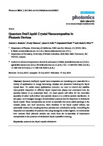
Figure (1) 4X4 Elliptical patch antenna
The antenna dimensions are as follows. The substrate height is 0.14mm, substrate length is 28mm and substrate width is 24mm, patch dimensions of 2.6mm along y and 2.2mm along x-axis. Feed length is of 6mm along y-axis. Total dimension of antenna is 34x32mm.
III.
Simulation Results Ansoft NameCorporation X 0.00 m1
36.1616
Return Loss
Y
Patch_Antenna_ADKv1
-18.7626
Curve Info dB(St(1,1)) Setup1 : Sw eep1
dB(St(1,1))
-5.00
-10.00
-15.00
m1
-20.00 20.00
25.00
30.00
35.00
40.00 Freq [GHz]
45.00
50.00
55.00
60.00
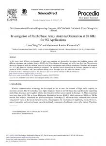
Figure (2) Return loss Vs Frequency
Figure (2) shows the return loss curve for the proposed antenna. A good antenna might have a value of -10dB as 90% of the signal is absorbed and 10% is reflected back. The current antenna model is giving the return loss of -18.78dB at the desired frequency 36GHz.
Volume 1, Issue 2, pg: 24-30
| 25
International Journal of Recent Trends in Electrical & Electronics Engg., Sept 2011. ©IJRTE ISSN: 2231-6612 Input Impedance
Ansoft Corporation
110
100
120 130
Patch_Antenna_ADKv1
90 80Curve Info 70 1.00 St(1,1)) 60
Setup1 : Sw eep1
0.50
2.00
rms
bandw idth(1, 0)
gaincrossover(1, 0)
phasemargin(1, 0)
0.8174
33.2042
20.0000
286.2384
50
140
40
150
30
160 0.20
5.00 20
170
10 0.20
180 0.00 -0.00
0.50
1.00
2.00
5.00
0
-170
-10
-160 -0.20
-5.00 -20
-150
-30
-140 -130
-40 -0.50
-2.00
-120 -110
-100
-1.00 -90
-50
-60 -80
-70
Figure (3) Input impedance smith chart
Figure (3) showing the input impedance smith chart for the antenna. Impedance matching should be perfect to transfer maximum amount of energy from one to another device. From the simulation results we got rms of 0.8174 and bandwidth of 0.91% enhancement and gain crossover of 20dB and phase margin of 286.23 is obtained.
Figure (4) 3D-gain
In many wireless systems an antenna is designed to enhance radiation in one direction while minimizing radiation in other directions. This is achieved by increasing the directivity of the antenna which leads to gain in a particular direction. The gain is thus the ratio of the radiation intensity, in a given direction, to the radiation intensity that would be obtained if the power accepted by the antenna were radiated isotropically (that is, equally in all directions). In the case of a receiving antenna, an increase in gain produces increased sensitivity to signals coming from one direction with the corollary of a degree of rejection to signals coming from other directions. Antenna gain is often related to the gain of an isotropic radiator, resulting in units dBi. Figure (40 showing the 3D-view of the gain of the antenna. A gain of 22dBi is obtained from the current model. Radiation Pattern 1
Ansoft Corporation
Patch_Antenna_ADKv1 Curve Info
0 -30
dB(rEPhi) Setup1 : LastAdaptive Phi='0deg'
30 -10.00
dB(rEPhi) Setup1 : LastAdaptive Phi='5deg'
-45.00 -60
60 -80.00
dB(rEPhi) Setup1 : LastAdaptive Phi='10deg'
-115.00 -90
90
dB(rEPhi) Setup1 : LastAdaptive Phi='15deg' dB(rEPhi) Setup1 : LastAdaptive Phi='20deg'
-120
120
-150
dB(rEPhi) Setup1 : LastAdaptive
150 -180
Volume 1, Issue 2, pg: 24-30
| 26
International Journal of Recent Trends in Electrical & Electronics Engg., Sept 2011. ©IJRTE ISSN: 2231-6612
Figure (5) & (6) Radiation pattern (phi direction) in polar coordinates and 3-Dimension
The radiation pattern represents the energy radiated from the antenna in each direction, often pictorially. The IEEE Definition states that it is “the spatial distribution of a quantity that characterizes the electromagnetic field generated by an antenna”. Most often this is the radiation intensity or power radiated in a given direction. Figure (5) and (6) shows the radiation pattern of the antenna in phi direction with respect to polar coordinates and 3-Dimensional view. Radiation Pattern 2
Ansoft Corporation
Patch_Antenna_ADKv1 Curve Inf o
0 -30
dB(rETheta) Setup1 : LastAdaptive Phi='0deg'
30 -10.00
dB(rETheta) Setup1 : LastAdaptive Phi='5deg'
-45.00 -60
60 -80.00
dB(rETheta) Setup1 : LastAdaptive Phi='10deg'
-115.00 -90
90
dB(rETheta) Setup1 : LastAdaptive Phi='15deg' dB(rETheta) Setup1 : LastAdaptive Phi='20deg'
-120
120
-150
dB(rETheta) Setup1 : LastAdaptive
150 -180
Figure (7) & (8) Radiation pattern (Theta direction) in polar coordinates and 3-Dimension
Figure (7) and (8) shows the radiation pattern of the antenna in theta direction with polar coordinates and 3-dimensional view.
Volume 1, Issue 2, pg: 24-30
| 27
International Journal of Recent Trends in Electrical & Electronics Engg., Sept 2011. ©IJRTE ISSN: 2231-6612
Figure (9) Axial ratio
The axial ratio is a parameter which measures the purity of the circularly polarized wave. The axial ratio will be larger than unity when the frequency deviates from f0. Figure (9) shows the axial ratio for the current model in 3-Dimensional view.
Figure (10) Directivity
Directivity is how much an antenna concentrates energy in one direction in present to radiation in other directions. It is equal to the power gain when antenna radiates equally in all directions. Figure (10) shows the directivity of the present antenna in 3-Dimensional view. Polarization of the wave radiated from an antenna describes the behavior of the electric and magnetic field vectors as they propagate through free space. Polarization is typically approximately linear. When linear the polarization may be further described as either vertical or horizontal based on the orientation of the electric field with respect to earth. This type of pattern can boost the signal strength due to its higher gain if aimed in the required direction. This comes at the expense of reduced effectiveness in other directions which may be desirable in certain applications. Highly directional antennas are desirable for point-to-point links and have application in automotive radar systems where a narrow beam may be scanned to detect nearby targets. Ansoft NameCorporation X 120.00 m1
36.1616
XY Plot 1
Y
Patch_Antenna_ADKv1
1.2607
Curve Info VSWRt(coax_pin_T1) Setup1 : Sw eep1
VSWRt(coax_pin_T1)
100.00
80.00
60.00
40.00
20.00
m1
0.00 20.00
25.00
30.00
35.00
40.00 Freq [GHz]
45.00
50.00
55.00
60.00
Figure (11) VSWR Vs Frequency
Volume 1, Issue 2, pg: 24-30
| 28
International Journal of Recent Trends in Electrical & Electronics Engg., Sept 2011. ©IJRTE ISSN: 2231-6612 Impedance mismatch between the transmission line and its load can be measured using VSWR curve. If the VSWR is high then the mismatch will be greater, the minimum VSWR corresponds to a perfect impedance match is unity. Figure (11) shows the VSWR curve with good agreement value of 1.26 at 36GHz.
IV.
Conclusion
4X4 array patch antenna was designed on liquid crystal substrate material and simulated using HFSS. This antenna is producing gain around 22dBi and bandwidth enhancement of 0.91%. The radiation pattern and other output parameters are showing superior performance over other traditional antennas and VSWR of less than 2 is obtained from the current model. This proposed antenna is flexible and compact in design to fit in the application specific environment. The gain crossover of 20dB and phase margin of 286.23 is obtained from the design. The results are giving encouragement for fabrication and testing this by using network analyzer.
Acknowledgments The authors like to express their thanks to the management of K L University and department of ECE for their support and encouragement during this work. Further, VGKM Pisipati acknowledges the financial support of Department of Science and Technology through the grant No.SR/S2/CMP-0071/2008.
REFERENCES [1]. B.T.P.Madhav, Prof. VGKM Pisipati, Prof. Habibulla Khan, VGNS Prasad, Prof. P.V.Datta Prasad, P.Sreekanth, “Microstrip Circular Patch Array Antenna For Wlan Applications On Liquid Crystal Polymer Substrate”, Journal of Emerging Trends in Computing and Information Sciences. , Vol. 2, No. 1, February 2011. [2]. B.T.P.Madhav, Dr. K. Sarat Kumar, Pranob K Charless, P.Sreyash, V.Satyasainadh, P.L.Madhuri, A.Snehitha, Saroj Gautam,” Rectangular Microstrip 6X6 Patch Array Antenna Performance Evaluation based on Permittivity of the Substrate Materials”, GJCAT, Vol 1 (1), 2011, 83-91, ISSN: 2249-1945 [3]. B.T.P.Madhav, Prof. VGKM Pisipati, P.Rakesh Kumar, N.V.K.Ramesh, K.V.L.Bhavani, Sri Jayalakshmi, 8x8 Array Elliptical Patch Antenna on Teflon Substrate Material for WLAN Applications, International Journal of Advances in Science and Technology, Vol. 2, No.5, 2011. [4]. Nashaat, D.; Elsadek, H.A.; Abdullah, E.A.; Iskander, M.F.; Elhenawy, H.M.; Hawaii Center for Adv. Commun., Univ. of Hawaii at Manoa, Honolulu, HI, USA,“Ultrawide bandwidth 2x2 microstrip patch array antenna using electromagnetic band-gap structure(EBG)”, Antennas and Propagation, IEEE Transactions on May 2011 ,Volume : 59 ,Issue:5 . [5]. Rahim, M. K. A. Asrokin, A. Jamaluddin, M. H. Ahmad, M. R. Masri, T. Aziz, M. Z. A. Abdul , Microstrip Patch Antenna Array at 5.8 GHz for Point to Point Communication, RF and Microwave Conference, 12-14 Sept. 2006 , 216 - 219. [6]. Khan, O.U.Electron. Eng. Dept., NED Univ. of Eng. & Technol. “Design of x-band 4x4 butler matrix for microstrip patch antenna array”, TENCON 2006. 2006 IEEE Region 10 Conference ,Issue Date: 14-17 Nov. 2006 On page(s): 1 – 4. [7]. Kanamaluru, S.; Ming-Yi Li; Kai Chang; Dept. of Electr. Eng., Texas A&M Univ, “Millimeter wave and far infrared science and technology”, 1996. Proceedings. 4th International Conference on Issue Date : 12-15 Aug 1996 . On page(s): 129 – 132. [8]. Ab Wahab, N.; Bin Maslan, Z.; Muhamad, W.N.W.; Hamzah, N.; Fac. of Electr. Eng., Univ. Teknol. MARA Malaysia, Shah Alam, Malaysia, “Microstrip rectangular 4x1 patch array antenna at 2.5ghz for wimax application, Computational Intelligence”, Communication Systems and Networks (CICSyN), 2010 Second International Conference ,Issue Date : 28-30 July 2010 ,On page(s): 164 – 168. [9]. T.A. Denidni, N. Hassaine and Q. Rao," Broadband High-Gain E-Shaped Microstrip Antennas for High-Speed Wireless Networks," Progress In Electromagnetics Research C, Vol. 1, pp. 105-111, 2008. [10]. Min Liu Zi-Rui Feng Fan-Yi Meng Feng-Lin Sun Qun Wu ,Dept. of Inf. Eng., Harbin Inst. of Technol., Harbin, “A 35GHz Cone Conformal Microstrip 4x4 Array”, Microwave Conference, 2007. APMC 2007. Asia-Pacific Issue Date: 11-14 Dec. 2007 On page(s): 1 – 4. [11]. Hooin Jung; Chulhun Seo; Dept. of Inf. & Telecommun. Eng., Soongsil Univ., Seoul, “Analysis of elliptical microstrip patch antenna considering attachment mode”, Antennas and Propagation, IEEE Transactions on Issue Date : Jun 2002 Volume : 50 , Issue:6 .
Volume 1, Issue 2, pg: 24-30
| 29
International Journal of Recent Trends in Electrical & Electronics Engg., Sept 2011. ©IJRTE ISSN: 2231-6612 [12]. Bailey, M.; Deshpande, M.;NASA Langley Res. Center, Hampton, VA USA, “Analysis of elliptical and circular microstrip antennas using moment method”, Antennas and Propagation, IEEE Transactions on Issue Date : Sep 1985 Volume : 33 , Issue:9 . [13]. Dane C. Thompson, O. Tantot, H. Jallageas, George E. Ponchak, Manos M. Tentzeris, and J. Papapolymerou, “Characterization of Liquid Crystal Polymer (LCP) Material and Transmission lines on LCP Substrates from 30 to 110 GHz”, IEEE Transactions on Microwave Theory and Techniques, vol. 52, no. 4, April 2004 [14]. Liquid Crystal-Reconfigurable Antenna Concepts for Space Applications at Microwave and Millimeter Waves, International Journal of Antennas and Propagation Volume 2009, Article ID 876989, 7 pages Author’s Details: B.T.P. Madhav was born in India, A.P, in 1981. He received the B.Sc, M.Sc, MBA, M.Tech degrees from Nagarjuna University, A.P, India in 2001, 2003, 2007, and 2009 respectively. From 2003-2007 he worked as lecturer and from 2007 to till date he is working as Assistant Professor in Electronics Engineering. He has published more than 52 papers in International and National journals. His research interests include antennas, liquid crystals applications and wireless communications. V.G.K.M. Pisipati was born in India, A.P, in 1944. He received his B.Sc, M.Sc and PhD degrees from Andhra University. Since 1975 he has been with physics department at Acharya Nagarjuna University as Professor, Head, R&D Director. He guided 22 PhDs and more than 20 M.Phils. His area of research includes liquid crystals, nanotechnology and liquid crystals applications. He visited so many countries and he is having more than 310 International research publications. He served different positions as academician and successfully completed different projects sponsored by different government and non-government bodies. He is having 5 patents to his credit. S. Susrutha Babu was born in India, A.P, in 1987. He received the B.Tech degree from JNTU, A.P, and M.Tech degree from SRM University, Chennai, Tamil Nadu, India in 2008 and 2010 respectively. He worked as Assistant Professor in Electronics Engineering in Bapatla Engineering College for academic year 2010-2011 and from 2011 to till date working in K L University. His research interests include antennas, FPGA Implementation, Low Power Design and wireless communications. S. Suparshya Babu was born in India, A.P, in 1987. He received the B.Tech degree from JNTU, A.P, and M.Tech degree from SRM University, Chennai, Tamil Nadu, India in 2008 and 2010 respectively. He worked as Assistant Professor in Electronics Engineering in Bapatla Engineering College for academic year 2010-2011 and from 2011 to till date working in K L University. His research interests include antennas, FPGA Implementation, Low Power Design and wireless communications.
Volume 1, Issue 2, pg: 24-30
| 30