ABSTRACT. The paper describes the desig of a controler for coopeerative robots designed at McGil University in a colaborative effort with the Jet Propukion ...
WP3 - 2:00 KALI: AN ENVIRONMENT FOR THE PROGRAMMING AND CONTROL OF COOPERATIVE MANIPULATORS
Vincent Hayward McGill Research Center for Intelligent Machines 3480 University Street, Montreal, Quebec Canada H3A 2A7 Samad Hayati Jet Propulsion Laboratory, Robotics and Teleoperators group 4800 Oak Grove Drive, Pasadena, California 91109
the dominant forces during transport become the inertial forces due to accelerations. Dealing with torques, in particular, demands the use of multiple manipulators, since two or more muaipulators can generate torques that are orders of magnitude larger than those generated by a single manipulator. The case of the transport problem effected by several manipulators is usually seen as an over-determined problem. Load balancing, may be used to constrain the problem. . Handling of non-rigid loads: In the case of non-rigid objects, a large class of tassks can be formulated in terms of stretching forces designed to give a predktable shape to the nianipulated object. The handling of cables, ropes, sheets, fabrics, and foils all require the use of multiple manipulators controlled to create mutual stretching forces. * Grasping: Grasping occurs when the size of a load is of the same order of magnitude as the limbs employed to constrain its motion. The simultaneous control of at least two limbs is a case of cooperative controL * Easing the task lay-out: The performance of a robot, in terms of the control of its velocity, applied forces, and position accuracy is a highly variable function of its posture. This is a prevailing consideration when designing the lay-out of a task. It turns out that, given the limited effective workrange of manipulators and the various geometrical requirements of a particular task, it may be hard to find a valid, let alone optimal, solution. We are dealing with finding the solution to a problem under a large number of constraints. The usage of multiple manipulators, viewed as the replacement of fixtures by robots, considerably increases the set of valid solutions. * Load mnobility: Load mobility may be an inportant factor. In such a case two or more robots can be particularly useful, because moving loads over large motions may easily cause a manipulator to reach its limits. Anyone familiar with programming robots has found it particularly difficult to program a regrasping sequence (2). The use of two robots, instead of just one and a table or a fixture, considerably increases the set of valid solutions, thus easing the task of finding one. Sinilarly, objects handed over from one robot to another could travel over large distances. In space, we suggest that throw and catch sequences might be an economical way of moving loads around. * However, properly aiming in space is no trivial task since there is no ground reference. When an object is thrown, it will not usually travel in straight line with respect to coordinates attached to the device that threw it. * Complexforce constraints: The configuration of a task may cause great difficulty for a single robot. For example, jamming can occur in such tasks as pushing drawers. The use of multiple manipulators makes it easier to control the proper balance of forces and torques that will lead to a convergence of the trajectory. This is particularly striking in the case of
ABSTRACT The paper describes the desig of a controler for coopeerative robots designed at McGil University in a colaborative effort with the Jet Propukion Laboratory. The first part of the paper discusses the background and motivation for multiple arm control. Then, a set of programming primnitives, whkh permit a programmer to specify cooperative tasks are described. Motion primitives specify asynchronous motions, master/slave motions, and cooperative motions. In the context of cooperative robots, trajectory generation issues are discussed and our implementa, tion briefly described. The relations between programming and control in the case of multiple robot are examined. Finally, the paper describes the allocation of various tasks among a multiprocessor computer.
INTRODUCTION Research in programming and control of manipulators requires appropriate experimental environments so the many available strategies can be evaluated. We describe a software package to be used to develop robot programs and their asociated control schemes in the context of multiple cooperating robots. The computer architecture to run this package is also discussed. Programming and control multiple robot manipulators represents a significant step in complexity and computational requirements with respect to the case of a single robot. We describe the choices we have made, and their implementation which is currently under way simultaneously at McGill University and at the Jet Propulsion Laboratory. As we go along, a number of references will be made to the RCCL system (1), which now has led to numerous projects (10,24,26,27). The discussion addresses several inter-related topks: * Conceptual: What are the relevant primitives for describing the tasks carried out by two or more cooperative robots? * Algorithmic: How can these primitives be implemented in terms of algorithms? * Control: What are the required control techniques, or in other words, which servo algorithms, which path planning techniques, and which models are needed? * Computer System: What is the appropriate computer architecture, given the current state of the art, in terms of tasks, computational requirements, and communication channels. As a background to our discussion, we first consider a selection of robotic tasks which, we believe, justify the endeavor to program and control two or more cooperating manipulators, further to Zapata et al.'s discussion (25). * Transport of inertial loads: Consider a task consisting of displacing a load whkh, because of its inertial properties, cannot be easily manipulated by a single manipulator. On earth, gravity forces usually limit the mass of the pay-load, unless gravity forces are dealt with by devices such as carts or a cranes. If no such device can be used, the gain in payload is expected to be approximately proportional to the number of manipulators. LI space or underwater, the gravity forces are greatly reduced or may become negligible. Thus,
- Marvin Minsky first suggested this possibility for earth applications.
473
the manipulation of elongated objects for whih a good control of torques and orientations is crucial. * Partial mutual kinematic relations/ip: As suggested by several authors (3), cooperative motions can be subject to a mixture mutual kinematic and force constraints. A an example, the task of manipulating scisors fals in this case. * Mutual position relationship: Sometimes, the environment requires two parts of the same task to be physicay separated. For example, riveting, or spot welding metal sheets as it is often required in the manufacture of cars or planes. Two cooperative robots, one on each side of the sheets, constitutes a more flexible set-up than a tool designed to wrap around the obstacle. * Highl3y redundant manipulators: The concept of micromanipulator (20,21,22) is increasingly attracting attention for high performance manipulation. This concept conists of mounting two manipulators with complementarycharacteristics within the same kinematic chain. For example, one serial manipulator-large workspace but high inertia- supporting a parael manipulator-small workspace but low inetia. The cooperative control of these manipulators leads to a stem featuring the combined advantages of both systems (23). * Locomotion: Mufti-legged locomotion can be viewed as a cooperative task, the reader is referred to the literature specific to this area. * Teleoperation: Last but not least, another posible option is the use of a pair of robots as a velocity/force reflectance system.
(b) Several arns are required
to move in velocity control mode with a known geometrical relationship. It is preferable to view this case as the programming of a single motion providing desired Cartesian coordinates set-points to two distinct
conutrol systems. (c) In order to account for the case of stretched soft objects, or objects squeesed by two or more manipulators, the overall velocities are specified, while mutual forces may be specified along certain directions. One single motion is more appropriately programmed along with internal force specifications. (d) Several arms rigdly connected to a common object, displacing that object in free space, or itself exerting forces on its environment. Again, we shall consider only one motion sending set-points to a single control system closed around several manipulUors. Note that one can exits some mutual constraints that can be specified in velocity or in force space (5,17). (e) Several arms acting on a common object in an asymmetric maner. For example for one arm to serve as a 'fixture' in velocity control mode, while others exert forces on the object. Two motions are programmed: one with respect to a reference frame, the other with respect to the first one. Note that there could carry out the classification of cass in a more general fashion. For example, one could consider that each link of a manipulator as an entity contributing to the realization of a common goal. It is however the essence of a cloed loop control stems to provide abstractions whkh are the ingredients of programming systenm. We feel that the above classification is made at the appropriate level.
CONCEPTUALIZATION
PREVIOUS APPROACHES The AL language was one of the first sptems to tackle the problem of programming multiple manipulators (7). The NSS system offers another perspective on this question in the context of robotc assembly (8). These systems, however, consider only cases of what we might cal 'loose cooperation'. They provide coordination and synchronisation by mean of concurrent threads of control and atomic events. These are prograuning mechanisms directly inspired from the programming of computers (9). This methodology takes care of simultaneous motions, mutual exclusion of workspace areas, but not of truly cooperative motions. The tasks involving two or more robots in clse cooperation such as in the cases mentioned in the previous section require a high degree of integration. Because there has been a significant increase of interest in the control of coordinated robots, there begin to exit systems specifically designed with close cooperation in mind (11). However, most of the research concentrates on control issues at the servo level, which has no other function than tracking a set-point (12,13), but little is available on the programming level and system synthesis.
The notion of 'motion sysem' generalises the notion of manipulator. A set of links, joints, and actuato with know kinematk and dynamic properties, usualy identified as a maniplator is a partkular case of a motion system. At the programming level, one coordinate frame is of particular interest: A frame attached to the last link of the manipulator, usualy through a fixed kinematic relationship. The role of the robot control system is to allow the programmer, human or automated, to ignore, to the greatest extent posible, the kinematic and dynamk properties of the underlying mechanical-stem, while specifying the motion of the coordinate frame in terms of velocities, forces and relationships of that motion with sensory information. Although the resulting manipulator program must saisfy a large number of constraints depending on the task, the manipulators themselves, and their environment, all specifications are made with respect to that -framne (4). In attempting to program multiple manipulators contributing to a common task, we see no reason for changing this paradigm. However, we are facing a greater degree of variability of motion sytems in whikh one, two, or several manipulators may be involved. Because of the tight interaction between manipulators, we require our system to pay a great deal of attention to (1) the dynamics of the system, (2) the quality of force control, (3) snchronisation and respect of time constraints, and (4) accuracy of path control. Deciding at whhkh degree of cooperation, distinct manipulators should be considered as one or several motion systems is an open question. For example, it seemn legitimate to consider two arms sharing a common lod as belonging to a single motion stem. It is however perfectly posible to consider also, under certain circumstances, that even though two arms are grasping a common object they can be controlled separately. It depen in fact, on the existence of a cloed-loop control algorithm capable of lumping two or more manipulators into a single system capable of tracking one common input. At the conceptual level, we have found the control and programming of cooperative manipulators to fall in the folowing
PROGRAMMING PRIMITIVES This section describes the building blocks which once put together make a robot program.
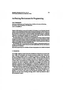
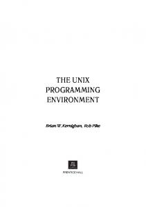
Spatial Relationships Positions are conveniently described by frame transformation graphs. In RCCL, those graphs adopt a ring structure (see figure 1).
cases:
(a) Several arms cary out different tasks occasionally synchroing with each other, either to avoid mutual collision or to move independently to meet at a rendes-vous in space-time.
rig
474
l
This graph is equivalent to the folowing equation: M T D C = Identity
Order of Evaluation. For each kinematic relationship, the order in whkh they must be evaluated is also specified. The normal order is: sensor-based functions, path planning function and, lastly, the manipulator transform update. Couping. For each kinematic relationship, the user can specify a 'coupling factor. This factor is normally set to 1, which means that all forces applied to an object attached to that relationship must be accounted for by the next object. For example, if a robot is holding an object in its gripper, all forces caused by the velocity, the acceleration and the gravity of that object will be transmitted to the next object which is the gripper, which in turn will be transmitted to the robot after having added the gripper's contribution. If an object is held by two robots, the factors, in the two forking branches will indicate how much each robot is expected to contribute dynamically. Dynamics. For each object involved in the task, the user is required to provide its dynamic model in terns of the acceleration terms, gravity terms, and velocity ternms. Pointers to functions returning these values must be specified. In the case of solid objects, this is easy, once the moments of inertia of an object are known, and standard functions are provided. In the case of the manipulators, the system provides standard functions to implement the dynamic models of the robots. For each relationship, the user may specify the maximum force that cani taken at the interface. For example, if a gripper can only generate a given gripping force, motions wiU computed such that this limit will not be violated. Of course, the normal usage of that feat'ure will be to ensure that motions wil never violate the manipulator's capabilities, which also come as standard functions. Timing tnformatvon. In a very accurate manner the user canl either specify desired velocity, motion segment timne, or scheduled arrival time. If these constraints cannot be enforced, an error condition will result, unless these constraints are explicitly relaxed. Transition Information. The properties of path transitions can be controlled by mean of two parameters as discussed below. The user can specify how close a trajectory should stick to a 'via point" and the type of trajectory wander is desirable in order to limit the acceleration. Control information. All terminating motions return an exit code which can be bound to an arbitrary external of internal condition. The execution of subsequent motions can be made conditional to a partiular exit code of the previous motion. Thus, this mechanism allows to specify alternative successors in a motion queue.
(1)
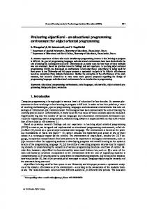
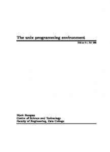
where M represents the "manipulator transform", T the transformation from the manipulator's last link to the controlled frame, the "tool transform", and C the coordinate transformation from where the tool should reach, to where the robot is located. The transform D or 'drive transform" has an initial value that reflects the position of the arm before the motion begins, and is interpolated toward the unit transforni in order to produce the desired motion. With two manipulators, as previously seen, the rings may share common transformation frames (see figure 2).
Fig. 2
In cases (b), (c), or (d), MA and M2 are manipulator transforms, T is the transform that takes into account the task constraints due to the environment as during sensor based motions or compliant motions, D is the "drive transform whose value is interpolated toward unity, such that upon motion termination, both position equations are satisfied. The principle is the same as in RCCL: a position is specified by whkh of the frames is the controLled frame and to which ap plies the motion constraints. Each actuated frame is associated with an accommodation framne to account for compliant motions, singularities, and joint motions. The total number of position controlled degrees of freedom remains always six. The various transforms are evaluated and contribute to the nominal values of the manipulator transforms. Arbitrary graphs can be created by mean of several loops. The nodes of several loops may point to the saune transform, in order to express mutual relationships.
Trajectory Computation
In RCCL as well as in Kali, the trajectories are viewed as a string of path segments connected by transitions. It is assumed that the velocity of the controled frame is the variable of concern during path segments. Accelerations are supposed to be small because the direction of the velocity should not change abruptly. On the other hand, during transitions, the acceleration is the variable of concern because of the velocity change. As a consequence the path must be allowed to wander off the ideal trajectory or the manipulator brought to a stop, that is giving up on tuning constraints. We have developed a transition computation method based on the blending of successive path segments. The type of blend is controlled by two factors. The preview factor conveys the amount of look ahead the system must perform before a transition. The acceleration factor conveys the amount of trajectory wander is admissible. These two factors, and the knowledge of the dynamics of the system lead to the automatic determination of the transition time. A smaller wander will lead to a longer acceleration period. This method is quite robust and is not affected by illdefined trajectories, such as thoses produced by tracking using sensory data, since it does not relv on bounidary conditions in position, velocity, and acceleration. The details of the miethod are
Motion Specifications The motion specifications apply to a motion system as discussed earlier. As in RCCL, they are captured by motion requests processed on a first in first out basis by a trajectory generator. The motion requests consist of records which contain all information pertaining to the cakulation of the trajectory. Goal position. It is described by a data structure describing the geometrical relationships of the goal position. Geometrical relationships fall in two cases. If there are m manipulators involved, there will be m kinematic loops described which will
have to share at least one relationship: the "drive transform", the transform that describes the common motion. For each kinematic relationship, the initial value of all transformations must be specified. If the relationship is not rigid it will be represented by what we call a 'bound transform". The user is then required to provide a pointer to a function to update it, and the transform becomes bound to that function. Transforms not bound to a function are called "free transforms". The simplest kinematic loop will include at least two non-rigid relationships, the "drive transform" and the "manipulator transform". Other non-rigid relationships are used to program sensor-based accommodation motions, parametric motions, etc...
available in a comnpanion report Synchronization
Motions are treated
475
as
(14).
processes, they are created, go
through
a sequence of states, and are eliminated from the system after a while. As it is common practke in software engineering, a process, when created, is represented as a record. Each motion is assigned an identification number that allows the controlling program to perform further references to this particular motion. Since motions are treated as individual processes, synchronisation between motions theiuselves is also easy to achieve through the combined use the iuotion control flags anid auction parameter such as velocity or time of arrival. The details are avaiable in a separate report (28).
these control lops. It is important to notice that our method stil allows us to generate joint-interpolated motions whikl using Cartesian based servoing, provided that the manipulators do not become singular. Several methods for dealing with singularities at trajectory level are currently being investigated by us and by others (29). In the case of single manipulators, the control algorithm may consists as in classical controllers of the inverse kinematics providing joint set-points to ordinary PID joint servo loops. It is however only one of the possible arrangements of our systemn.
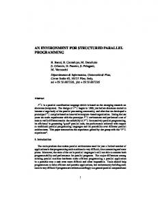
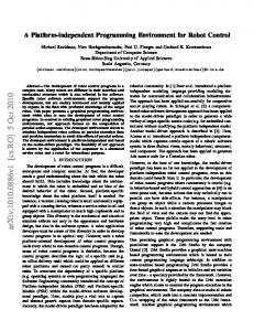
SERVOING AND CONTROL If a task requires a great deal of mechanical coupling anong the manipulators, effective control can only be achieved in a control loop which is ckeed around the entire system, and not only around each individual manipulator. Hayati (15,16) (see figure 3, extracted from (16)) has developed a multiple manipultor control scheme based on an extension of Raibert and Craig's hybrid control (17) and Khatib's operational space control (see figure 4, extracted from (18)). When using such a scheme, a moticon system can be seen as a point in the velocity and force subspaces. The input to the control is a noiminal trajectory specified in Cartesian coordinates.
ORGANIZATION Run Time Structure The run time structure consists of a set of processes, some of whih are high priority synchronous processe, some others are low priority and may execute asynchronously. The processors are distributed over an array of processrs connected by a bus. Details will be given further on in the discussion. The task alloation reflects the attempt to minimnise bus traffic, and sychronized inter-process communications. Short delays are paranmount to obtain adequate control. In many other proposed architectures, pipelining i seen as a method for inproving control by augmenting the computational through-put. Unfortunately, this approach fails to take into account that the benefits of high rats are often ost in the computations delays spent in the stages of a pipeLined architecture which caue the correction signals to be computed on stale data. To improve the control rate, we adopt a different approach based on the considetation of the physis of the plant to be controlled, on the structure of the control algorithm (18,19), and the evolution of today's computing technology. First, rapidly changing quantities (control error, for example) are updated more often than slowly changing ones (inertia characteristics, for example). Second, parallelism is achieved by observing that certain computations, within one sample period, can be performed independently from others, and by allocating them on a limited number of concurrently running processors. Although it has been observed that a great deal of paralelism can be achieved in this fashion at the cost of great hardware complexity, we have preferred to niake use make a limited use of it in favor of simplicity. Finally, the technology of processors is rapidly improving performance and we base our design on conservative projections. Synchronous Pocesses. As in RCCL, there exists a main synchronous process whose task is to compute nominal set-points for the manipulattrs. This process is time-shared for all instances of motion systems. Others synchronous processes implement the servo control algorithm. There is also also a synchronous I/O process which runs at the same frequency as the servo process. This process is in charge of gathering sensor iinformation: joint position, current, wrist force readings, etc... and post them in a shared area of memory. Asynchronou processes. The maim asychronous process is the so-caUed 'user process'. It is the process that contains the 'robot program'. Its mains functions are: presetting the transformation values, setting up the kinematic loops, issuing the motion requests, synchronizing itself with the task execution, and petforming I/0 with the exterual world. The other asynchronous processes are related to the dynamic computatlons. These processes can run asynchronously because the performance of the system wil degrade only slowly if the data they produce is a little bit 'old' (19). Five of these processes are needed per robot. The first one computes three sets of forces created by the velocity terms under various conditions: before and after a potential transition, and for the current set-point. The second one compute the current gravity terms. The third one updates the inertia matrix. One other compute the maximum force the robot can produce. Communications and Processor Allocat:orn. In ordet to make the minimum of assumptions with respect to the performance of the underlying operating system, onl two forms of communication are considered: Message passing, which is inev-itably
Plums 1. P.psend IObit P..ttlem/Pnn e..snl inok astSe aw bit-As at
Fig. 3
PwFWtnSJLw o Lrc.. Operaticl Spac Cased ArcmtSrs
FiS. 4
a
These schemes form the control error in task space and drive
highly non-linear plant. To compensate for this, feed-forward
dynamics are used to linearize and decouple the system. Our Cartesian coordinates trajectory generator with acceleration demand limitation is designed to effectively provide set-points to
476
nions. This layer also includes kinematic and dynamic models for
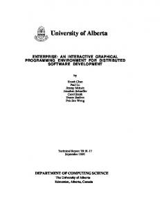
rather slow but appropriate to transfer information across different processors, and shared memory with no explicit synchronization mechanism, whkh allows to use these forms of communication: Without data loss: Type 1. Message queues from the asynchronous processes to the synchronous ones. Type 2. Message buffers from one synchronous process to its successors. Type 3. Atomic event flags. With possible data loss: Type 4. Data updated and utilized by any process with no need of explicit synchronization nmechanism. The trajectory generator communicates with synchronous because users written monitor functions need to have access to fresh external information (Type 4). No explicit synchronization is required, because the latest update of such values as force sensor readintgs, and digital I/O lines assigned to a fixed located in shared memory need to be read. The trajectory generator transmits set-points to the servo process processes at a fixed rate (Type 2). The servo process and the i/o process run at the samue nmultiple rate of the trajectory generator rate. The dynamic computations are left runntng on a dedicated processor with no explicit synchronization. They need external 10 data to obtain the robot state variables. They produce data located in fixed place in shared memory to be read at leisure by the other processes. Priorities are adjusted to insure adequate perforniiance. The user process commnunicates with the external world through ordiniary I/O over the Ethernet. This process is likely to use very little CPLT tinie and sinice it communicates mostly with the trajectory generator (Type I and 3), conveniently shares a processor with it, on which the motion queue also resides. This way, the motioni synichronizationi which mostly consists of manipulatious in the niotion queue buffer is simple to iniplement. See figure 5 for a suniniuary. I
2
our Puma robots.
and
The third software layer implements the servo control code
uses the above
layers.
The fourth layer is the heart of Kali. It consists of two libraries. The 'rings' library contain code to maintain and update in real time kinematics loops. As discussed earlier, loops are ornented graphs whose nodes point to transformation values. Each node is attached to a function which specifies the 'method' to update the value. Provision is made for the sanie function to be attached to several nodes. Also, if a value is shared by several loops, the update will take place only once. Internmediate values, results of transform multiplies, are stored into an internal hash table in order to avoid redundant compputationss. There is nlo need to keep track explicitly of the fact ttlat the same kinematic relationship may be used several times. The other library, the 'motion' library, contains the 'method' to compute siimooth interpolated Cartesian coordinate trajectories according to a variety of constraints specified in a 'motion record'. Robot programs using the 'motion' library can be extremely verbose. The fifth layer may consist a set a funiction to emulate RCCL functions in terms of third and fourth layer calls. However, it might be worthwhile customizing new sets a functions, based on specific needs. For example, niultiple arm motion primitives such as "foHlow-the-leader, move-rendez-vous, accommodatewith-each-other, lift-with-squeeze, or two-hand-twist" can be defined at that level.
COMPUTING SYSTEM From the control point of view, we encounter stringent cornputational requirements. Estimation shows that we shall require a system capable of executing at least 10 million floating point instructions per second. Such a computational requirement calls for the allocation of distributed coniputing systeni. We have selected an arrangement consisting of a number of identical single board computers based on Motorola's M020/68881 chips sharing a commion VME backplane. All the code developmnent is done in C and is made on a SUN work-station under Unix connected via Ethernet to the VME backplane. The particular system we have selected features secondary VSB buses. We nake use of these bu-ses for high-speed point to point communication between the processors without affecting the VME bus bandwidth. We have felt that this combination was offering us the best performance, complexity and cost ratio, while providing a large third party product support.
Geo~~~~~*eral 10
r-*--~ lftxrii-
i. :..t::.f ~~~~~Twnpwl |
CONCLUSION
i _- AsVNarssC u*,attns _
Srrw1ca~ COrnifltuScatfr
..,.
L
The design of a multi-manipulator multi-processor control system has been discussed. It results from the balance between a large number of various requirements. In many cases, simplicity has taken precedence over efficiency. We have have sought to achieve generality through the elaboration of a number of building blocks that can be combined in various ways, rather than attenipting to establish a rigid framework such as those offered by designs based on the selection of pre-determined options. Specific applications can be developed by mean of function libraries. imiacro processing, or dedicated languages. The initial version of Kali will be available summer 1988 through NASA's COSMIC technology development program.
..
C~meerl
Fig. 5 Software Organization Not counting the real-time operating system level, the software is divided in roughly five layers which may consist each of several libraries. The bottom layer is meant to provide a development environment for the development of closed loop control code. It provides an interface for programming closed loop control laws, usually understood by the user as a "block diagram" or a set of equations, between the user and a real time multi-processor operating system. The second function of this software layer is to establish the environment suitable for running the various synchronous and asynchronous processes described above. The second software layer is also a support layer and is totally independent from the operating system. It consists of several small utility libraries. Currently there is a library for buffered input and output of data, useful for debugging and dumping data into files. The 'geo' library is a set of function for geometrical computations on vectors, transforns, and quater-
ACKNOWLEDGMENTS John Lloyd, Laeeque Daneshmend, Ajit Nilakantan, and Tony Topper contributed to this paper.
The research described in this paper has been funded by the Jet Propulsion Laboratory under contract with the National Aeronautics and Space Administration, and by Natural Science and Engineering Research Council of Canada.
REFERENCES
(1) Hayward, V., Paul, R. P. 1987 (Winter). Robot manipulator control under unix: RCCL a robot control 'C' library, International Journal of Robotic Research, Volume 5, Number 3.
477
(20) Reboulet, C., Berthomieu, T. 1987 (October). Hybrd position force control implementation on a parallel manipulator. Nato Advanced Research Workshop on kinematicad dynamic issues in senJor baed control.
(2) Tourassous, P., Lozano-Pert'z. T, and Maser, E. 1987. Regrasping. 1987 IEEE Internatnal Conference on Robotics and Automation, Raleigh, North Carolina. pp. 1924-1928.
(3) Mason, M. T., 1981. Comphli.acte ntld force control for computer controlled manipulators. IFT! 'Trczn.gations on Systems, Man, and Cybernetics, SMC-ll loiine 19$l.1,pu. 418-432.
(2'1) Inoue, H., Tsusaka, Y., Fukuisumi, J. 1985. Parallel munipulator Robotic Research, Jrd ISRR, Cambride, MA, MIT Press. (212) Tlevelyan, J. P., Kovesi, P. D., Ong, M. C. H. 1985. Motion control of a sheep shearing robot. Robotic Research, 3rd ISRR Cambride, MA, MIT Press.
(4) Paul, R. P. 1981. Robot mans peat'r mathematics, programming, and controL. MIT Press, Cambridge.Nkiss.
(5) Salisbury, J. K., Craig, J. 1982 (Spritng). Art-iculated hands: force and Kinematic Isues. The Internatonal Journal of Robotics Research, Volume 1., Number I.
(23) Hayward, V., 1987 (July). An integrating survey of robot manipulator control and connections with their biological counterparts. McGill Research Center for Intelligent Machines Technical Report, C[M-87-13, McGill University Montrdai, Canada.
(6) Brooks, T. L. 1981 Optimal path generation for cooperating robots or redundant manipulators. Jet Propulsion Laboratory Technical Report.
(24) Lloyd, J., Parker, M., McClain, R. 1988 Extending the RCCL progamming environment to multiple robots aad processors IEEE Int. Conf. on Robotics and Autoration. Philadelphia,
(7) Mujtaba, S., and Goldman, R. 1981. AL users's manual. AIM-344, Stanford, Calif., Stanford University Artificial Inteli gence Laboratory.
Pa
(25) Zapata, R., Fourier, A., Dauches P 1987. True cooperation of robots in multi-arms task. -IEEE Int. ('nsf. on Robtics and Automation. Raleigh, Pa
(8) Alanii, R., and Chochon H. 1985 (April). Prograniming of flexible assembly cells: task modeling and system integration. IEEE International Conference on Robotics and Automation, St. Louis.
(26) Ouptill, R., Stahwara, P. 1987. Muliple robotics device, Position specification and coordination IEEE Ita. Conf. o* Robotics and Automation. Raleigh, Pa
(9) Dijkstra, E. W. 1968. Cooperating Sequential Processes. In: Programming Languages, F. Genuys (Ed.), Academic Press, New
(27) Koesman, D., Malowany, A. 1987. A multi-processor Robot control system for RCCL under iRMX. IEEE Int Coaf. on Robotics and Automation. Raleigh, Pa
York.
(10) Lee, J. S., Hayati S., Hayward, V., Lloyd, J. E. 1987. Implementation of RCCL, a robot control C library on a mncroVAX It. Intelligent Robots and Computer Vision: Fifth in a Series, D. Casasent, Editor, Proc. SPE 726
(28) Nilankatan, A., Hayward, A. 1988. Synchroising Multiple Manipulators. Second Interationtal Symposium on Robotics and Manufacturing Research, Educatio ad Applications, Albuquerque, New Mexico.
(11) IEEE Conference on Robotks and Automation, 1987, Session on Multi-Arm Robots, pp. 1236-1255.
(29) Aboaf, E. W., Paul, R. P. 1987. Living with the singulaity of robot wrists. IEEE Int. Cosf. on Robotics and Automation. Raleigh, Pa
(12) Clark, C. J., and Stark, L. 198 (April). A comparison of control lws for a cooperative robot system. IEEE International Conference on Robotics and Automation, San Francisco. pp. 390394.
(13) Zheng, Y. F., and Luh, J. Y. S. 1986 (April). Joint torques for control of two coordinated moving robots. 1985 IEEE International Conference on Robotics and Automation, San Francisco, California. (14) Hayward, V. Model based trajectory planning using preview. McGill Research Center for Intelligent Machines Technical Report, In preparation. (15) Hayati, S. 1987 (January). Dynamics and control of coordinated multiple manipulato. Jet Propulsion Laboratory/NASA workshop on Space Robotics, Pasadena, California. (16) Hayati, S. 1986 (April). Hybrid position/force control of multi-arm cooperating robots. IEEE International Conference on Robotics and Automation, San Francisco. pp. 82-9.
(17) Raibert, M. H., and Craig, 3. J. 1981. Hybrid position/force control of manipulator. Trans. ASME J. Dynamic Syst., Meas., Contr., Vol 103, pp. 126-133. (18) Khatib, O., Burdik, 3. 196 (April). Motion and force control of robot manipulaton. IEEE International Conference on Robotics and Astomation, San Francisco. pp. 1381-1386.
(19) Isaguirre, A., Hashimoto, M., Paul, R. P., Hayward, V. 1987 (September). A new computational structure for real-time dynamics. IEEE International Workshop on Robotics Trends, Technology and Applications, Madrid, Spain.
478