Missing:
PAPER KINECT-BASED UNIVERSAL RANGE SENSOR AND ITS APPLICATION IN EDUCATIONAL LABORATORIES
Kinect-based Universal Range Sensor and its Application in Educational Laboratories http://dx.doi.org/10.3991/ijoe.v11i2.4299
Mingshao Zhang, Zhou Zhang, Yizhe Chang, Sven K. Esche & Constantin Chassapis Stevens Institute of Technology, Hoboken, New Jersey, USA
Abstract—Traditional data acquisition (DAQ) systems for obtaining 3-D range information consist of sensors, DAQ measurement hardware and a processor with software. This kind of DAQ system is adapted and calibrated for various applications, thus imposing significant up-front costs that hamper its broad usage in educational laboratories. The low-cost Microsoft Kinect has become a promising alternative solution that has already been widely adopted by consumers and offers a wide variety of opportunities for being used in many other areas. The Kinect’s cameras are capable of producing high quality synchronized video that consists of both color and depth data. This enables the Kinect to compete with other sophisticated 3-D sensor DAQ systems in terms of performance criteria such as accuracy, stability, reliability and error rates. One of the most noticeable Kinect-based applications is the skeleton-based tracking of humans, which is made possible by its built-in human skeleton recognition functions. Other common usages of the Kinect are 3-D surface/scene reconstruction and object classification/recognition. However, Kinect-based developments that focus on the tracking of arbitrary objects have rarely been reported, mainly due to a lack of mature algorithms. In the first part of this paper, a three-stage approach for capturing general motions of objects will be introduced. This approach consists of point cloud pre-processing with a focus on computational efficiency, object tracking employing recognition and post-processing including motion analysis. This approach can be tailored to special cases, namely the algorithms focus more on computation efficiency when the objects of interest have simple shapes or colors, and they focus more on reliability for objects with complex geometries or textures. The second part of this paper describes the integration of the proposed DAQ system into a multi-player game-based laboratory environment. In this implementation, a physical experiment is triggered by the game avatars and the experimental data acquired by the Kinect and analyzed by the proposed algorithms are then fed back into the game environment and used to animate the experimental device. Index Terms—Engineering Education, Laboratory Development, Microsoft Kinect, Data Acquisition, Object Recognition, Motion Tracking.
I. INTRODUCTION Laboratories are widely acknowledged to have significant educational value for engineering and science students. They often use a data acquisition (DAQ) system for the measurement and analysis of certain parameters characterizing physical phenomena [1]. However, the wide
26
usage of DAQ systems is hampered by various factors, including the high cost of sophisticated sensors, the need for adapting and calibrating them for different experiments, which results in long operating times. In traditional educational laboratory setups, the sensors used to measure range data (linear/angular position, velocity, etc.) are usually simple and only capture one degree of freedom (i.e. one direction of translation or rotation) at a time. A system that can measure complex spatial motions requires at least one set of devices (i.e. sensor and its supporting hardware) for each degree of freedom. However, this makes such a system too difficult to be built, modified, calibrated and maintained. One feasible alternative solution for tracking complex motions is using a 3-D scanner, which can determine the geometry, location and posture of objects at each scan and then use multiple scans to track objects. While 3-D scanners offer these potentially powerful functions and outstanding accuracy, they also exhibit various shortcomings. Commercially available 3-D scanners with high scanning speed and accuracy are very expensive. Furthermore, all 3-D scanners require a rotating platform to be used, need to be integrated with a DAQ system and typically have a limited frame rate that prevents them from being used for tracking fast movements [2]. In light of these considerations, a low cost and easy to use sensor such as the Kinect becomes a desired substitute. Compared to other sophisticated 3-D scanners, the Kinect has a compatible range of measurement, field of view, acceptable accuracy, resolution, sensitivity, stability and error rate [3, 4, 5]. A lot of developments aiming to improve some of the inadequate performance characteristics of the Kinect have been reported, such as noise modeling [6], temporal denoising [7] and hole filling [8]. These efforts make the Kinect a more suitable scanner for use in educational laboratories. In addition, the processing of the Kinect data is flexible and can be controlled and revised just by programming approaches without any hardware modifications. A smart DAQ system composed of a Kinect and a personal computer has several advantages over traditional 3-D scanner systems, namely the setup for measurements is easier, calibration is performed automatically, no hardware modifications are needed for different experiments and the time needed for users to learn how to operate the system is short [9,10]. In order to maximize the laboratory’s learning effectiveness for the students, this Kinect-based universal range sensor can also be used to integrate physical experimental devices into a massively multiplayer online game environment (e.g. Gary’s Mod), thus creating a mixed reality collaborative laboratory environment [11]. Such a gamebased laboratory environment enables distance learning,
http://www.i-joe.org
PAPER KINECT-BASED UNIVERSAL RANGE SENSOR AND ITS APPLICATION IN EDUCATIONAL LABORATORIES which allows the sharing of limited educational resources with a larger audience and makes it easier for students to repeat experiments [12]. This laboratory environment also enables students to assemble and disassemble the experimental devices, which gives the users a similar feeling of immersion as traditional hands-on laboratories. The integration of physical experiments into a virtual laboratory system enables student collaboration and provides a hands-on feeling at the same time [13]. II. BACKGROUND ON KINECT APPLICATIONS A. Overview of Common Applications Since its release in November 2010, the Kinect has not only become one of the most popular game consoles that has been widely accepted by consumers, but it also captured the attention of researchers and developers. A large number of Kinect-based applications have emerged since then and the Kinect has been proved to have great potential in various areas. Among these applications, the most common ones can be categorized into two groups based on the methods used to process the Kinect’s raw data. Applications of the first kind are known as human skeleton tracking, which are popular for two reasons. First, the Kinect was originally designed as a game interface that uses gestures of the human body as command inputs for controlling games. Second, Microsoft provided a Software Development Kit for the Kinect, in which the kinematic information on the major joints of the human skeleton is available to users, thus easing the difficulty of the development work. These applications include human detection [14], physical rehabilitation [15], sign language recognition [16], etc. Based on the hardware components, the Kinect is essentially a structured-light scanner. The second kind of applications deals with the point cloud generated by the Kinect directly. It is mostly motivated by the intention of using the Kinect as a substitute for commercial 3-D scanners, due to their high price and unavailability to consumers. Among these applications, there are still some that focus on problems related to the human body, such as hand gesture tracking [17] and face scans [18]. Others are similar to traditional 3-D scanner applications, such as indoor environment modeling [19,20], 3D surface reconstruction [21,22,23], alternative sensor for educational experiments [24,25], etc. B. Kinect-based Motion Flow Tracking In order to use the Kinect in educational laboratories for objecting tracking, the most straightforward solution is to adopt motion tracking algorithms from computer vision. Methods that extract the optical flow for tracking the motions of objects’ in 2-D image sequences or videos have been studied extensively and a large number of algorithms have been developed, such as the Lucas-Kanade method [26] and the Horn-Schunck method [27]. Motivated by the goal of enabling the construction of 3-D images from 2-D ones through triangulation methods and also leveraging the emergence of powerful 3-D scanners, numerous algorithms for tracking motions in general 3-D space have been developed. Some of these algorithms were adapted in Kinect applications for tracking 3-D motion flows from RGB-D data, for instance by generalization of two-frame variational 2-D flow algorithms to 3-D applications [28], based on the particle scene flow [29] and by using multi-
iJOE ‒ Volume 11, Issue 2, 2015
ple Kinects to handle large arbitrary motions and subpixel displacements [30]. Many of the above-mentioned algorithms have been proved to be robust and suitable to be implemented in various applications. However, estimating all six degrees of freedom of the objects’ motions in 3-D space directly by motion flow tracking techniques is inefficient and inaccurate. Additional complications arise from the fact that complex scenes may potentially contain multiple moving objects as is common in laboratory applications, which renders it difficult to track only the motion of the objects of interest. In order to solve this problem, a system with the capability of distinguishing multiple moving objects from each other is desired. C. Kinect-based Object Recognition Object recognition is already a rather mature research topic in computer science, and many algorithms have been demonstrated to function adequately in various situations, such as Scale-invariant Feature Transform (SIFT) [31] and Speeded-up Robust Features (SURF) [32] which are used for 2-D object recognition, as well as Viewpoint Feature Histogram (VFH) [33] and spin images [34] for 3-D object recognition. Many of these algorithms have been adapted for the development of Kinect-based applications, including obstacle and game element detection [35], object recognition using a depth kernel descriptor and sparse distance learning [36], object detection based on multiple Kinects [37] as well as 3-D object recognition and 6 DOF pose estimation [38]. Most of these developments focus either on 3-D feature detection and extraction or on object recognition and classification. As will be discussed below, the 6 DOF pose estimation algorithm is a great candidate for being directly adapted into part of the motion tracking system presented here. III. METHODOLOGY FOR KINECT-BASED DATA ACQUISITION A. System Overview In order to serve as a substitute for a traditional data acquisition system in educational experiments, the proposed Kinect-based system should provide certain functions, the most important once being that it should be able to distinguish multiple moving objects both from the background and from each other, recognize among these moving objects those that are of interest, and track these objects of interest by computing the changes in their six degrees of freedoms over time. The raw data produced by the Kinect are sequences of point clouds where each frame contains a large number of points with associated color and location information. In order to achieve the above-mentioned functionality with appropriate efficiency and accuracy, the Kinect-based system consists of algorithms that can be divided into three stages as described in detail in the sections below. The first stage, namely pre-processing, includes functions such as scene segmentation to improve the computational speed and noise removal to enhance the accuracy of the computed results if needed. Depending on the complexity of the geometry and texture of the objects of interest, different algorithms are chosen for object recognition in the second stage. The post-processing is the last stage, in which the changes in objects’ six degrees of freedom are computed.
27
PAPER KINECT-BASED UNIVERSAL RANGE SENSOR AND ITS APPLICATION IN EDUCATIONAL LABORATORIES B. Data Pre-processing
2
1) Noise Removal Compared to other 3-D scanners, the Kinect has some significant disadvantages. For instance, it exhibits a slightly higher noise level and the accuracy of its measurements decreases with increasing distance or view angle. This noise is illustrated for example by the image of a flat wall that is located far away from the Kinect and thus is distorted into numerous flat subparts with different depth values (see Figure 1 left). These subparts, which actually belong to the same wall, are treated by traditional motion detection algorithms as potentially moving objects since their depth values change randomly in different frames, thus increasing the required computation time and inducing unnecessary errors. One of the commonly used noise removal algorithms is called statistical outlier removal, which is also available in the open-source Point Cloud Library (PCL) [39]. In the prototype implementation presented here, a statistical
g ( x ) = #! ( d ( x )) ( f ( xi ) " fi ) .
Here, d ( x ) = x ! xi is the Euclidian distance of the point under consideration from the remaining points of the point cloud. Then, ! ( d ) is a scalar weight function of d
1 , wherein the parameter ! is d +"2 set to a small nonzero value to prevent a possible singularity. Also, the value of ! determines the rate of the decrease in the scalar weight function ! ( d ) and thus affects the interpolating characteristic of the MLS function g ( x ) . Furthermore, fi refers to the original depth value
according to ! ( d ) =
x !"2 , min g ( x )
Figure 1.
28
2
at point i, and f ( x ) is its interpolated value, which is defined as:
µ
and standard deviation ! of the analysis of the mean distances of all points to their K (here K = 100 ) nearest neighbors is performed, and those points with a mean distance larger than a certain preset threshold (here Dthreshold = ! ) are marked as noise and therefore trimmed from the point cloud. This technique works well for removing low level measurement noise, but it is not suitable for eliminating significant measurement errors such as the wall distortion mentioned above. The result of the noise removal using this approach is illustrated in the middle image of Figure 1. However, holes are inevitably induced by the filtering of outliers, in particular along the boundaries between the subparts of the distorted wall. In addition, this algorithm has to traverse twice through the chosen neighboring points for all points of the entire point cloud, which is too computationally expensive. A feasible and popular approach to address the wall distortion problem and remediate low level noise or random measurement errors is to smoothen and interpolate 3-D points, using methods such as Moving Least Squares (MLS) [40]. In this method, for each point, a certain weighted MLS function g is minimized over a predefined 2-D domain according to:
(2)
i
f ( x) = b ( x) c
(3)
Here, b ( x ) = !#b1 ( x ) ,..., bk ( x )"$ is a polynomial basis T
vector and c = [c1 ,..., ck ] is a vector of unknown coefficients, which is used to minimize the weighted MLS function g. For instance, for quadratic interpolation in 3-D defined as space, b ( x ) is
b ( x ) = !#1 x
y xy x 2
y 2 "$ and c is computed by:
# T$ c ( x ) = % )! ( di ) b ( xi ) b ( xi ) & ' i (
"1
)i ! ( di )b ( xi ) fi
(4)
The result of the quadratic MLS interpolation for the wall example is shown in the right image of Figure 1. This example demonstrates that when interpolation of a high enough order is used over a sufficiently large search radius, the individual subparts from the original scan data are eliminated and thus no longer identified as potentially moving objects. However, this method is computationally expensive, even when using only linear interpolation.
(1)
Top view of scene; left: original as acquired by Kinect; middle: filtered using outlier noise removal; right: resampled using quadratic interpolation
http://www.i-joe.org
PAPER KINECT-BASED UNIVERSAL RANGE SENSOR AND ITS APPLICATION IN EDUCATIONAL LABORATORIES Also, the MLS method has limited effect in restoring the wall distortion when the errors are large. Unfortunately, no efficient algorithm has been developed yet to solve this particular problem. In the prototype development of the educational laboratory presented here, the Kinect is stationary with respect to and relatively far away from the background scene. Therefore, one feasible solution to address the distorted wall problem is to build a pass through filter in the depth direction to remove all the points belonging to the wall. Referring to Figure 2 as illustration, a histogram evaluation is used to analyze the distribution of depth values of the entire point cloud. A large number of points are located on or near the distant wall and thus have higher measurement errors due to their large distances. A threshold is determined using the result from histogram analysis and only those points with depth values smaller than the preset threshold are kept for further usage. Conveniently, the spurious NaN errors generated by the Kinect at points where the infrared projector cannot calculate the depth value are also trimmed. In addition, the low level measurement noise problem is also addressed in the next stage of processing, namely the change detection. 2) Selective Segmentation The Kinect generates point clouds with a pixel resolution of 640!480, resulting in a total of 307,200 points. The implementation of any object recognition or motion tracking algorithms that use point clouds of this size as input is computationally expensive. Thus, applications that require close to real-time processing speed are rendered too difficult to develop. In object recognition applications, segmentation algorithms are usually used as pre-processing methods that segment scenes (i.e. image, depth map, point cloud, etc.) into several subparts. Subsequently, the chosen object recognition and motion tracking algorithms need to be applied only within those subparts that contain the objects of interest. During the first step of implementation, the entire scene is searched in order to detect significant changes between point clouds, and only neighborhoods where motion is detected are segmented out as input for further computation. 3) Octree Change Detection Change detection in 3-D point clouds can be a difficult task due to various reasons. Specifically, the topology cannot be assumed to be the same for point clouds that originate from different sources, often occlusions (e.g. holes in point clouds) occur during data collection, and large datasets require efficient data handling routines. In light of these considerations, the octree data structure (a 3D data structure that may reduce the amount of time and memory needed for data pre-processing) shows its suitability as a point cloud data representation. Its advantages include that it can be used in point clouds stemming from any sources (i.e. different formats generated by different scanners), the process is almost automatic and requires very limited user interaction, and the computation speed can be optimized by adjusting the search radius and time [41]. A sample implementation is shown in Figure 3, where one of the recorded motion scenes is randomly chosen as reference. By comparing the remaining motion scenes with the reference, only the neighborhoods that may potentially contain a moving object are segmented out for further analysis. However, if some of the motion scenes coincidentally have the moving objects at the same
iJOE ‒ Volume 11, Issue 2, 2015
Figure 2. left: original laboratory scene; right: depth value histogram of point cloud
Figure 3. Laboratory environment; left: reference scene; middle: regular scene; right: result of octree change detection
location as the reference one, no change is detected. Thus, the resulting data are missing at this particular frame. This problem can be mediated by interpolating the resulting data. This approach dramatically reduces the required computation time in the subsequent processing steps, such as object recognition and motion tracking. C. Tracking Methods and Data Post-processing! 1) Description of Suitable Tracking Methods Traditional tracking methods focus on either the optical flow in 2-D images or the motion flow in 3-D space. In these methods, the flow can be interpreted as the location changes of different groups of 2-D pixels or 3-D points, which gives the observer a general understanding of the motions. In order to distinguish the differences between various motions in the scene and to track only the objects of interest, algorithms that were originally designed for object recognition can be adapted and integrated into the applications discussed here. Based on the complexity of the potential objects’ texture and geometry, recognitionbased tracking methods can be divided into three groups: color/texture-based tracking (suitable for simple scene scenarios but limited reliability of results in other conditions), simple geometry tracking (suitable when objects have simple geometry regardless of texture conditions), and complex geometry tracking (preferred for intricate objects or scenes, work better if integrated with texturebased tracking methods). 2) Color/Texture-based Tracking One of the most important criteria for evaluating algorithms that track moving objects is the computation speed. Among all the available methods that have been developed, recognition methods using the objects’ color and texture are the fastest. Their implementation can be as simple as building a pass through filter that only keeps the points with color values within a certain preset range. In the pass-through filter approach, there is no need to con-
29
PAPER KINECT-BASED UNIVERSAL RANGE SENSOR AND ITS APPLICATION IN EDUCATIONAL LABORATORIES struct a multi-dimensional data structure for storing the points’ values (e.g. coordinates and color) and their complicated connections with each other. Furthermore, the original data structure of the point clouds generated by the Kinect is kept and the recognition process can be implemented using a simple comparison. The limitation of this method is that the color of the objects of interest must be unique. Thus, this method can only be applied for certain simple applications and yields poor results otherwise. Similar to the color-based approaches, texture-based tracking methods can be implemented in point cloud applications by compressing the 3-D data into 2-D images (i.e. omitting the depth values). By doing so, most of the geometric relations between points are lost. Also, this approach simplifies the object recognition problem in 3-D space to its counterpart in 2-D images. All 2-D object recognition algorithms (such as the SIFT and the SURF mentioned above) can be employed to detect certain keypoints on the objects of interest in the compressed 2-D images. Then, these keypoints are traced back to the original 3-D point cloud and used to compute the changes in the positions and orientations of the objects of interest. One problem of these methods is that significant distortions may occur during the transformation between 3-D point clouds and 2-D images. In certain situations, these distortions may hamper the robustness of the 2-D object recognition algorithms and the accuracy of motion estimation. Common approaches for object recognition consist of two main stages, namely extracting and subsequently comparing keypoint descriptors. The problems caused by the above mentioned distorted transformations originate in the first stage. One feasible approach that can lead to more reliable results is to use higher dimensional keypoint descriptors such as multi-dimensional SIFT descriptors (in the case of recognition-based motion tracking, SIFT descriptors in 3-D space are sufficient). In contrast to the well known 3-D SIFT developed by Scovanner et al. [42], which added the time as an extra dimension to the original 2-D descriptors for classifying actions in video sequences y and t ), the method proposed (i.e. 3-D here refers to x , by Allaire et al. [43] extended the descriptors from 2-D y y and z ). images (i.e. x and ) to 3-D spaces (i.e. x , This technique starts by extending the scale space using the 3-D Gaussian blur operator G, followed by finding the keypoints at the maxima/minima of the Difference of
D ( x, y, z, ! )
Gaussian (DoG). The DoG image as:
is defined
D ( x, y, z, ki! ) = L ( x, y, z, ki! ) # L ( x, y, z, ki #1! ) L ( x , y , z , ki ! ) = G ( x , y , z , k i ! ) $ I ( x , y , z ) G ( x , y , z , ki ! ) =
1
(
2" ki!
3
)
e
(
)
# x 2 + y 2 + z 2 / 2( ki! )
(5) 2
Here, G ( x, y, z, ! ) is the Gaussian blur operator and ! is the standard deviation of the Gaussian distribution of the points’ grayscale value, I ( x, y, z ) is the grayscale
value of the original input image, ki and k j are scalar numbers used to define the scale of the Gaussian blur.
30
The next few steps include finding keypoints, eliminating bad keypoints (i.e., false keypoints induced by image noise or computational errors) and calculating the gradient direction and magnitude around the keypoints. In the final step, the descriptors are created, which typically consist of 64 histograms aligned in a 4!4!4 grid, each with 8 azimuth directions and 4 elevation directions, thus resulting in a feature vector containing 2,048 elements. These resulting vectors are known as SIFT keys and are used for a nearest-neighbors search aimed at identifying possible matches within images. 3) Tracking of Simple Objects In many educational laboratories, especially those that conduct physics experiments, most of the targeted moving objects tend to have simple geometries. Among the algorithms that focus specifically on extracting primitive shapes, two are widely known, namely the Hough transform [44] and the RANSAC paradigm [45]. In the prototype application presented here, the RANSAC approach is used for shape detection. This method has been proven to work effectively in 2-D as well as 3-D applications. Its advantages included that its conceptual simplicity make it straightforward to be implemented and easily to be extended, it requires very limited modification for being used in a wide range of applications and it works robustly even with the presence of high outlier proportion (i.e. high noise level). The main disadvantage of the traditional RANSAC method is that it has low computational efficiency and high memory demands, which are both less severe in this application because the size of the input point cloud is dramatically reduced by the above mentioned motion segmentation process. Also, a more efficient RANSAC method is adopted and implemented here [46]. The RANSAC paradigm can be used for detecting several different shapes, include plane, sphere, cylinder, cone, etc. Table 1 lists the important parameters for implementing the RANSAC paradigm for some simple shapes, namely the input parameters, the output parameters and their computation methods, and acceptance criteria. Here, the sphere detection is used as a prototype implementation. The RANSAC paradigm works by randomly drawing minimal point sets from the input point cloud and computing the corresponding shape primitives. Two points ( p1 , p2 ) and their corresponding normal vectors (n1 , n2 ) can be used to fully define a sphere. The center c of this computed sphere is defined as the midpoint of the shortest line segment between the two lines that are given by the above mentioned two points and their normals, and the sphere radius is calculated as described in Table 1. The computed sphere is treated as an acceptable candidate if all points are within a certain distance ! from the sphere’s surface and their normal vectors deviate by less than a certain angle ! from that of the sphere. The result of detecting a sphere is shown in Figure 4 The motion changes of this sphere can be tracked through implementing the RANSAC detection in all consecutive point cloud frames. 4) Tracking of Complex Objects Tracking methods that are limited to simple texture or primitive shape objects are not always sufficient for educational applications. For instance, in robotic experiments, the target objects tend to have complicated geometries and
http://www.i-joe.org
PAPER KINECT-BASED UNIVERSAL RANGE SENSOR AND ITS APPLICATION IN EDUCATIONAL LABORATORIES TABLE I. RANSAC PARAMETERS AND CRITERIA FOR SHAPE DETECTION Shape Input parameters (position vectors pi
Output parameters
of minimal point set, corresponding normal vectors ni)
Plane
( p1, p2 , p3 ), (n1, n2 , n3 )
(a, b, c, d ) Result vectors defining plane as:
Sphere
( p1 , p2 ), (n1, n2 ) ( p1 , p2 ), (n1, n2 )
a,
r=
c, r
c of sphere centroid and radius of p1 ! c + p 2 ! c
2
Direction of cylinder axis tion when projecting lines onto plane
( p1, p2 , p3 ), (n1, n2 , n3 ),
p1
a = n1 ! n2 , c is intersec-
p1 + tn1 and p2 + tn2
a ! x = 0 , radius r
Differences between normal vectors n1 , n2 , n3 of 3 points are less than a preset angle ! All points are within a certain distance ! of sphere’s surface and their normals deviate by less than a certain angle ! from normal of sphere All points are within a certain distance ! of cylinder’s surface and their normals deviate by less than a certain angle ! from normal of cylinder
is distance between
c c, a, ! Apex c is intersection of 3 planes defined by those 3 and
Cone
ax + by + cz = d
c, r Position vector sphere
Cylinder
Acceptance Criteria
in this plane
points and their normals, direction of cone axis
All points are within a certain distance ! of cone’s surface and their normals deviate by less than a certain angle ! from normal of cone
! p #c p #c p #c " a = $c + 1 ,c+ 2 ,c+ 3 %, p1 # c p2 # c p3 # c %' $& # i arccos (( pi " c ) a ) opening angle ! = 3 with finding keypoints by using the least square method to fit a quadratic interpolation surface to the neighboring points and trimming those points that fall outside of a certain distance t from their respective interpolation surp is computed as: faces. Then, the shape index S at point S ( p) =
Figure 4. Scene with a spherical object; left: input point cloud after octree motion segmentation; lower right: result of RANSAC sphere detection; upper right: estimated sphere parameters
textures, such as wheeled robots and helicopters. One of the most difficult tasks involved in recognizing arbitrarily shaped objects is to find an efficient way to represent their surfaces. In early approaches for 3-D object recognition, curved surfaces are segmented into planar surfaces and treated as polyhedral objects. Subsequently, various representation methods for arbitrarily shaped surfaces were explored. These approaches all struggle with two main problems, namely how to represent the surfaces and how to match them efficiently. In the application presented here, an efficient method that uses local surface patches to recognize free-form objects [47] is adopted and implemented. Like many other recognition methods, it starts
iJOE ‒ Volume 11, Issue 2, 2015
k1 ( p ) + k2 ( p ) 1 1 " tan "1 2 ! k1 ( p ) " k2 ( p )
(6)
Here, k1 and k 2 are the maximum and minimum principal curvatures of the quadratic interpolation surface, respectively. Then, a point is selected as a keypoint if its shape index satisfies either one of the following criteria: (i) S ( p ) is the local maximum and it is larger than 1 " 2 ! S or (ii) S ( p ) is the local minimum and it is less n 1 1 than ! S . Here, ! and ! are preset scalar pa" n2 rameters. For each keypoint, its N nearest neighboring points are set as a local patch and the following parameters are computed and stored in a hash table: the surface type, the centroid of this local patch and a histogram. The surface type of a local patch is obtained based on the Gaussian and mean curvatures of the feature point [48]. For each point belonging to this local patch, its shape index and the angle between its normal and the normal at the keypoint is computed. Those shape indexes and angles form the above-mentioned histogram. The hash tables are used to find matches between the target object models and the input point clouds. Then, the centroids of the matched local patches of the keypoints are used to calculate the rigid transformation of the object of interest. The result of this method is shown in Figure 5.
31
PAPER KINECT-BASED UNIVERSAL RANGE SENSOR AND ITS APPLICATION IN EDUCATIONAL LABORATORIES
Figure 5. Complex object recognition; left: input point cloud; lower right: reference robot model; upper right: estimated motion
IV. GAME-BASED PROTOTYPE SYSTEM A. Game-based Education Systems Video games attract consumers by many elements, such as exciting adventures playing out in fascinating scenarios, high-fidelity audio effects, near-real 3-D graphics, realistic real-world physics simulations as well as the strong engagement of the players. Along with these advantages, multiplayer online games also include communication modules to enable the remote interactivity between users [49]. Although most games are designed for entertainment purposes, the basic function included in game engines such as graphics support, physics simulation and story plots make the games suitable for educational usage [50]. A game-based multi-user virtual laboratory environment that integrates a remote pendulum devices was developed as a pilot application. This experiment was designed to use the Kinect to capture the motion of a Foucault pendulum and uses the algorithm package discussed above to compute the parameters of the pendulum’s motion and to animate the experiment inside of the virtual environment in real time. B. Data Analysis and Preparation for Game Environment Some of the results from the above mentioned motion tracking and object recognition cannot be used directly as input data for the game-based educational environment presented here. For instance, the result of motion tracking is a series of point clouds that contain the moving objects of interest. In a DAQ system for educational purposes, the characteristic parameters of the objects’ motions need to
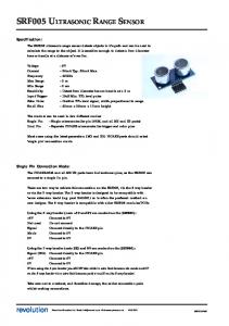
be extracted from these point clouds. These data can then either directly represent the results of the experiment or they can serve as input data for the virtual laboratory environment. Even after being extracted, the characteristic parameters of the motions still need to be analyzed and prepared in a presentable format. Consider as an illustration the case where the motion of a robot is to be tracked. As the final output of each point cloud, a location coordinate and a direction vector of the tracked robot could be computed. By drawing these coordinates and directions into the same map, the motion of the robot can be visualized. Furthermore, from the position data found at discrete time intervals, additional kinematic parameters (e.g. linear and angular velocity, acceleration, etc.) can be computed. As an illustrative example of the approach described above, a Foucault pendulum experiment involving a spherical bob was chosen as a prototype implementation (see Figure 6). Only the points that represent the spherical part are extracted from a series of point clouds and the bob positions (x, y, and z coordinate of the sphere’s centroid) are computed and recorded. The result is shown in Figure 7 Based on the small pendulum amplitudes, the bob stays in almost the same latitude (i.e. small changes in y coordinate). The noisiest part is the change in the z coordinate, which is reasonable because the Kinect has the lowest accuracy in the depth direction. From the position data, the gravitational acceleration g can then be calculated to be 9.77m / s 2 , which is acceptably accurate in light of the measurement errors caused by the Kinect and the small angle approximation used in the calculations.
Figure 6. Experimental setup of Foucault pendulum
Figure 7. Pendulum tracking result; left: result plot of x, y, z coordinates, right: result plot in x-z plane
32
http://www.i-joe.org
PAPER KINECT-BASED UNIVERSAL RANGE SENSOR AND ITS APPLICATION IN EDUCATIONAL LABORATORIES C. Communication between Kinect Device and Game Environment The massively multiplayer online game used in this application is Garry’s Mod [51] (also known as GMod), which is based on Half-Life 2’s ‘Source’ game engine and written in a revised Lua language [52] called GMod Lua. To enable the game environment to communicate with the Kinect-based DAQ software package, a Dynamic Link Library (DLL) and shared memory were implemented as middleware. The DLL is an application of shared libraries in the Microsoft Windows operating system, which consists of code, data, and binary files for the operating system, custom resources or any combination thereof. This technique is preferable for the application presented here because the C++ is used as programming language in the software package, and *.dll files compiled in C++ can be directly loaded by the GMod game server. GMod’s C Application Program Interface is also capable of embedding functions or variables into the *.dll files. A simple flow chart demonstrating the communication between the DAQ software package and the GMod game sever is depicted in Figure 8.
shared memory, which can be read/written from both the server and user sites in real-time. D. Game Environment Setup In the game environment, users (i.e. students, instructor, and teaching assistant) are represented as avatars. The users can send commands to the actuators in the physical experimental setup through the game interface (e.g. to initialize or change the input parameters for the experiment), conduct the experimental procedure, collect the feedback from the sensors (i.e. the Kinect) and observe the real-time animation of the experiments [13]. This approach mimics a hands-on laboratory and gives the users a feel of immersion, allows them to observe the physical phenomenon in action and benefit from collaborative learning. The implementation of this concept is shown in Figure 10 The users can see a real-time animation of the pendulum experiment and are presented with a summary of the computed results in the form of a pop-up window.
Figure 8. Communication between DAQ package and GMod game server
The communication scheme mentioned above can only realize simple callback functions for the variables packed in the *.dll files, but it cannot exchange data between different software platforms and different processes. In order to overcome this limitation, a shared memory was allocated, which enables the access of different processes to the DAQ software package and the GMod game sever. This approach improves the efficiency in exchanging data between different platforms by avoiding unnecessary copies of the static libraries’ instances [11]. A conceptual illustration of the structure of the shared memory between the DAQ software package and the GMod game server is shown in Figure 9 (refer to [11] for technical details of the implementation).
Figure 9. Communication structure of shared memory
There are two methods for realizing the communication between the Kinect-based experimental setup at the server site and the virtual laboratory, which could be located remotely at the user site. For some time-insensitive experiments, an off-line batch mode processing method can be used, taking advantage of its simplicity in the implementation. The Kinect DAQ package analyzes the experiment and stores the results in data files, sends them to the game server at the user site. The data are then used to animate the experimental setup within the virtual environment. Commands from the users are sent using the same method. For real-time applications, all variable (including experimental results and user commands) are stored in the
iJOE ‒ Volume 11, Issue 2, 2015
Figure 10. Foucault pendulum experiment implementation in a game environment
V. CONCLUSION AND FUTURE WORK In this paper, the recent progress made in developing object recognition algorithms, motion tracking algorithms and Kinect related applications was reviewed. Three categories of algorithms for pre-processing, recognition-based motion tracking and post-processing were implemented. Point cloud data pre-possessing was used to achieve better tracking results and higher computational efficiency. Inspired by algorithm developments in both the object recognition and motion tracking areas, recognition-based motion tracking methods for robust tracking that can be used in different application scenarios were designed. Post-processing for motion analysis and data preparation for animation in a game environment was implemented. A pilot implementation of a virtual laboratory with an integrated experiment was developed and tested. The Kinect was proven to be a suitable and powerful sensor substitute for universal range data acquisition. This game-based educational laboratory environment has shown great potential as a new education tool. In the near future, more object recognition and motion tracking algorithms will be tested and integrated into this DAQ software package in an attempt to find the best solutions for different applications. More experiments will be designed and integrated into this game-based virtual laboratory environment. Furthermore, a primitive machine learning based decision making system will be integrated
33
PAPER KINECT-BASED UNIVERSAL RANGE SENSOR AND ITS APPLICATION IN EDUCATIONAL LABORATORIES into the software package, which will enable the system to assess the complexity of a particular experiment and to automatically choose the best combination of algorithms for this experiment. ACKNOWLEDGMENTS Portions of the work presented here were carried out as part of a multi-disciplinary research project with funding from a multi-year grant by the National Science Foundation (Award No. 0817463). This support is gratefully acknowledged. Also, the authors wish to thank Dr. ElSayed Aziz and Dr. Serdar Tumkor for many stimulating discussions on the topic.
[14]
[15]
[16]
REFERENCES [1]
[2] [3] [4]
[5] [6]
[7]
[8]
[9]
[10]
[11]
[12]
[13]
34
Estrada, H. and Kim, R., 1997, “Application of Data Acquisition Systems in the Undergraduate Laboratories of Mechanical Engineering and Engineering Science,” Proceedings of the 27th Annual Frontiers in Education Conference, November 5, 1997, Pittsburgh, Pennsylvania, USA, pp 454-460. http://dx.doi.org/10.1109/ FIE.1997.644921 Blais, F., 2004, “Review of 20 Years of Range Sensor Development,” Journal of Electronic Imaging, 13(1), 231-243. http://dx.doi.org/10.1117/1.1631921 Khoshelham, K., 2011, “Accuracy Analysis of Kinect Depth Data,” Proceeding of ISPRS workshop on laser scanning, Calgary, Alberta, Canada, August 29-31, 2011. Chow, J., Ang, K., Lichti, D., and Teskey, W., 2012, “Performance Analysis of a Low-Cost Triangulation-Based 3d Camera: Microsoft Kinect System”, Proceedings of The International Archives of the Photogrammetry, Remote Sensing and Spatial Information Sciences, Melbourne, Australia, August 25 – September 1, 2012. Dutta, T., 2012, “Evaluation of the Kinect™ Sensor for 3-D Kinematic Measurement in the Workplace,” Applied Ergonomics, 43(4) 645-649. http://dx.doi.org/10.1016/j.apergo.2011.09.011 Nguyen, C. V., Izadi, S., and Lovell, D., 2012, “Modeling Kinect Sensor Noise for Improved 3D Reconstruction and Tracking,” International Conference on 3D Imaging, Modeling, Processing, Visualization and Transmission, Zurich, Switzerland, October 1315, 2012, pp 524-530. Essmaeel, K., Gallo, L., Damiani, E., De Pietro, G., and Dipanda, A., 2012, “Temporal Denoising of Kinect Depth Data”, International Conference on Signal Image Technology and Internet Based Systems, Sorrento-Naples, Italy, November 25-29, 2012, pp. 4752. http://dx.doi.org/10.1109/SITIS.2012.18 Camplani, M., and Salgado, L., 2012, “Efficient spatio-temporal hole filling strategy for Kinect depth maps,” Proceedings of Three-Dimensional Image Processing and Applications II, Burlingame, California, USA, January 22, 2012. Zhang, M., Zhang, Z., Aziz, E.-S., Esche, S. K. and Chassapis, C., 2013, “Kinect-Based Universal Range Sensor for Laboratory Experiments,” Proceedings of the ASME International Mechanical Engineering Conference & Exposition IMECE'13, San Diego, California, USA, November 13-21, 2013. Zhang, M., Zhang, Z., Esche, S. K. and Chassapis, C, 2013, “Universal Range Data Acquisition for Educational Laboratories Using Microsoft Kinect”. Proceedings of the 2013 ASEE Annual Conference & Exposition, Atlanta, Georgia, USA, June 23-26, 2013. Zhang, Z., Zhang, M., Tumkor, S., Chang, Y., Esche, S. K. and Chassapis, C, 2013, “Integration of Physical Devices into GameBased Virtual Reality,” International Journal of Online Engineering, 9(5) 25-38. http://dx.doi.org/10.3991/ijoe.v9i5.2705 Corter, J. E., Esche, S. K., Chassapis, C., Ma, J. and Nickerson, J. V., 2011, “Process and Learning Outcomes from Remotely Operated, Simulated, and Hands-On Student Laboratories,” Computers and Education, 57(3) 2054-2067. http://dx.doi.org/10.1016/ j.compedu.2011.04.009 Tumkor, S., Zhang, Z., Zhang, M., Chang, Y., Esche, S. K. and Chassapis, C, 2012, “Integration of a Real-Time Remote Experi-
[17]
[18]
[19]
[20]
[21]
[22]
[23] [24]
[25]
[26]
[27] [28]
ment into a Multi-Player Game Laboratory Environment,” Proceedings of the ASME International Mechanical Engineering Conference & Exposition IMECE'12, Houston, Texas, USA, November 9-15, 2012. Xia, L., Chen, C.-C. and Aggarwal, J., 2011, “Human Detection Using Depth Information by Kinect,” 2011 IEEE Computer Society Conference on Computer Vision and Pattern Recognition Workshops, Colorado Springs, Colorado, USA, pp. 15-22. http://dx.doi.org/10.1109/CVPRW.2011.5981811 Chang, Y., Chen, S. and Huang, J., 2011, “A Kinect-Based System for Physical Rehabilitation: A Pilot Study for Young Adults with Motor Disabilities,” Research in Developmental Disabilities, 32(6) 2566-2570. http://dx.doi.org/10.1016/j.ridd.2011.07.002 Zafrulla, Z., Brashear, H., Starner, T., Hamilton, H. and Presti, P., 2011, “American Sign Language Recognition with the Kinect,” Proceedings of the 13th International Conference on Multimodal Interfaces, Alicante, Spain, pp. 279-286. http://dx.doi.org/10.1145/ 2070481.2070532 Oikonomidis, I., Kyriazis, N. and Argyros, A. A., 2011, “Efficient Model-Based 3D Tracking of Hand Articulations Using Kinect,” Proceedings of the 22nd British Machine Vision Conference, Dundee, Scotland, UK, pp. 1-11. http://dx.doi.org/10.5244/ C.25.101 Zollhöfer, M., Martinek, M., Greiner, G., Stamminger, M. and Süßmuth, J., 2011, “Automatic Reconstruction of Personalized Avatars from 3D Face Scans,” Computer Animation and Virtual Worlds, 22(2-3) 195-202. http://dx.doi.org/10.1002/cav.405 Henry, P., Krainin, M., Herbst, E., Ren, X. and Fox, D., 2012, “RGB-D Mapping: Using Kinect-Style Depth Cameras for Dense 3D Modeling of Indoor Environments,” The International Journal of Robotics Research, 31(5) 647-663. http://dx.doi.org/10.1177/ 0278364911434148 Zhang, Z., Zhang, M., Chang, Y., Aziz, E.-S., Esche, S. K. and Chassapis, C., 2013, “Real-Time 3D Model Reconstruction Using Kinect for a Game-Based Virtual Laboratory,” Proceedings of the ASME International Mechanical Engineering Conference & Exposition IMECE'13, San Diego, California. Izadi, S., Kim, D., Hilliges, O., Molyneaux, D., Newcombe, R., Kohli, P., Shotton, J., Hodges, S., Freeman, D. and Davison, A., 2011, “Kinectfusion: Real-Time 3D Reconstruction and Interaction Using a Moving Depth Camera,” Proceedings of the 24th Annual ACM Symposium on User Interface Software and Technology, Santa Barbara, California, USA, pp. 559-568. http://dx.doi.org/10.1145/2047196.2047270 Lim, Y.-W., Lee, H.-Z., Yang, N.-E. and Park, R.-H., 2012, “3-D Reconstruction Using the Kinect Sensor and its Application to a Visualization System,” International Conference on Systems, Man and Cybernetics, Seoul, Korea, pp. 3361-3366. http://dx.doi.org/10.1109/ICSMC.2012.6378311 Ozbay, E. and Cinar, A., 2013, “3D Reconstruction Technique with Kinect and Point Cloud Computing,” Global Journal on Technology, Vol. 3, pp. 1748-1754. Zhang, M., Zhang, Z., Aziz, E.-S., Esche, S. K. and Chassapis, C., 2013, “Kinect-based Universal Range Sensor for Laboratory Experiments,” Proceedings of the ASME International Mechanical Engineering Conference & Exposition IMECE'13, San Diego, California, USA. Zhang, M., Zhang, Z., Esche, S. K. and Chassapis, C., 2013, “Universal Range Data Acquisition for Educational Laboratories Using Microsoft Kinect,” Proceedings of the 2013 ASEE Annual Conference & Exposition, Atlanta, Georgia, USA. Lucas, B. D., and Kanade, T., 1981, “An Iterative Image Registration Technique with an Application to Stereo Vision,” Proceeding of 7th International Joint Conference on Artificial Intelligence, Vancouver, Canada, pp. 674-679. Horn, B. K., and Schunck, B. G., 1981, “Determining Optical Flow,” Artificial Intelligence, 17(1) 185-203. http://dx.doi.org/10.1016/0004-3702(81)90024-2 Herbst, E., Ren, X., and Fox, D., 2013, “RGB-D Flow: Dense 3-D Motion Estimation Using Color and Depth,” IEEE International Conference on Robotics and Automation, Karlsruhe, Germany, May 6-10, 2013 http://dx.doi.org/10.1109/ICRA.2013.6630885
http://www.i-joe.org
PAPER KINECT-BASED UNIVERSAL RANGE SENSOR AND ITS APPLICATION IN EDUCATIONAL LABORATORIES [29] Hadfield, S., and Bowden, R., 2011, “Kinecting the Dots: Particle Based Scene Flow from Depth Sensors,” 2011 IEEE International Conference on Computer Vision (ICCV), Barcelona, Spain, November 6-13, 2011, pp. 2290-2295. http://dx.doi.org/10.1109/ ICCV.2011.6126509 [30] Letouzey, A., Petit, B., Boyer, E., and Team, M., 2011, “Scene Flow from Depth and Color Images,” Proceedings of the 22nd British Machine Vision Conference, Dundee, Scotland, August 29September 2, 2011, pp. 1-11. http://dx.doi.org/10.5244/C.25.46 [31] Lowe, D. G., 1999, “Object Recognition from Local ScaleInvariant Features,” Proceedings of the 7th IEEE International Conference on Computer Vision, Kerkyra, Greece, September 2027, 1999, pp. 1150-1157. http://dx.doi.org/10.1109/ICCV. 1999.790410 [32] Bay, H., Ess, A., Tuytelaars, T., and Van Gool, L., 2008, “Speeded-up Robust Features (SURF),” Computer Vision and Image Understanding, 110(3) 346-359. http://dx.doi.org/10.1016/j.cviu. 2007.09.014 [33] Rusu, R. B., Bradski, G., Thibaux, R., and Hsu, J., 2010, “Fast 3d Recognition and Pose Using the Viewpoint Feature Histogram,” IEEE/RSJ International Conference on Intelligent Robots and Systems (IROS), Taipei, Taiwan, October 18-22, 2010, pp. 21552162. http://dx.doi.org/10.1109/IROS.2010.5651280 [34] Johnson, A. E., and Hebert, M., 1999, “Using Spin Images for Efficient Object Recognition in Cluttered 3D Scenes,” IEEE Transactions on Pattern Analysis and Machine Intelligence, 21(5) 433-449. http://dx.doi.org/10.1109/34.765655 [35] Greuter, M., Rosenfelder, M., Blaich, M., and Bittel, O., 2011, “Obstacle and Game Element Detection with the 3D-Sensor Kinect,” Research and Education in Robotics - EUROBOT 2011, Vol. 161, pp. 130-143. [36] Lai, K., Bo, L., Ren, X., and Fox, D., 2013, “RGB-D Object Recognition: Features, Algorithms, and a Large Scale Benchmark,” Consumer Depth Cameras for Computer Vision, Springer, pp. 167-192 http://dx.doi.org/10.1007/978-1-4471-4640-7_9 [37] Susanto, W., Rohrbach, M., and Schiele, B., 2012, “3D Object Detection with Multiple Kinects,” Proceedings of Computer Vision–ECCV, Workshops and Demonstrations, Springer, pp. 93102. [38] Aldoma, A., Marton, Z.-C., Tombari, F., Wohlkinger, W., Potthast, C., Zeisl, B., Rusu, R. B., Gedikli, S., and Vincze, M., 2012, “Tutorial: Point Cloud Library: Three-Dimensional Object Recognition and 6 DOF Pose Estimation,” Robotics & Automation Magazine, 19(3) 80-91. http://dx.doi.org/10.1109/MRA.2012. 2206675 [39] Website of Point Cloud Library, http://pointclouds.org/, accessed on April 16th, 2014. [40] Lancaster, P., and Salkauskas, K., 1981, “Surfaces Generated by Moving Least Squares Methods,” Mathematics of Computation, 37(155) 141-158. http://dx.doi.org/10.1090/S0025-5718-19810616367-1 [41] Barber, D., Holland, D., and Mills, J., 2008, “Change Detection for Topographic Mapping Using Three-Dimensional Data Structures,” International Archives of Photogrammetry, Remote Sensing and Spatial Information Sciences, 37(B4) 1177-1182. [42] Scovanner, P., Ali, S., and Shah, M., 2007, “A 3-Dimensional Sift Descriptor and Its Application to Action Recognition,” Proceedings of the 15th international conference on Multimedia, Augsburg, Germany, September 24-29, 2007, pp. 357-360. http://dx.doi.org/10.1145/1291233.1291311 [43] Allaire, S., Kim, J. J., Breen, S. L., Jaffray, D. A., and Pekar, V., 2008, “Full Orientation Invariance and Improved Feature Selectivity of 3D SIFT with Application to Medical Image Analysis,” IEEE Computer Society Conference on Computer Vision and Pattern Recognition Workshops, Anchorage, Alaska, USA, June 2328, 2008, pp. 1-8. http://dx.doi.org/10.1109/CVPRW.2008. 4563023 [44] Hough, P. V., 1962, “Method and Means for Recognizing Complex Patterns,” In US Patent, 1962. [45] Fischler, M. A., and Bolles, R. C., 1981, “Random Sample Consensus: A Paradigm for Model Fitting with Applications to Image
iJOE ‒ Volume 11, Issue 2, 2015
[46]
[47]
[48]
[49] [50]
[51] [52]
Analysis and Automated Cartography”, Communications of the ACM, 24(6) 381-395. http://dx.doi.org/10.1145/358669.358692 Schnabel, R., Wahl, R., and Klein, R., 2007, “Efficient RANSAC for Point!Cloud Shape Detection,” Computer Graphics Forum, 26(2) 214-226. http://dx.doi.org/10.1111/j.1467-8659.2007.010 16.x Chen, H., and Bhanu, B., 2007, “3D Free-Form Object Recognition in Range Images Using Local Surface Patches,” Pattern Recognition Letters, 28(10) 1252-1262. http://dx.doi.org/10.1016/ j.patrec.2007.02.009 Bhanu, B., and Nuttall, L., 1989, “Recognition of 3-D objects in range images using a butter"y multiprocessor,” Pattern Recognition, 22(1) 49–64. http://dx.doi.org/10.1016/0031-3203(89)900381 Chang, Y., Aziz, E.-S., Esche, S. K. and Chassapis, C., 2013, “A Framework for Developing Collaborative Training Environments for Assembling,” Computers in Education Journal, 23(4) 44-59. Torrente, J., Moreno-Ger, P., Martínez-Ortiz, I., and FernandezManjon, B., 2009, “Integration and Deployment of Educational Games in E-learning Environments: the Learning Object Model Meets Educational Gaming,” Educational Technology & Society, 12(4) 359-371. Garry’s Mod, developed by Garry Newman, http://garrysmod.com/, accessed on April 16th, 2014. Ierusalimschy, R., 2006, “Programming in LUA,” 2nd Edition, lua.org.
AUTHORS Mingshao Zhang, Zhou Zhang, Yizhe Chang, Sven K. Esche, and Constantin Chassapis are with the Stevens Institute of Technology, Hoboken, New Jersey, USA. Submitted 04 December 2014. Published as resubmitted by the authors 10 March 2015.
35