He is now with the Department of Computer and. Information ... modalities is that the subject must use assistive devices such as crutches or a walker to maintain.
TO APPEAR: IEEE TRANS. ON SYSTEMS, MAN, AND CYBERNETICS, VOL. 26, NO. 11, NOV. 1996
1
Kinematic Modeling of Four-Point Walking Patterns in Paraplegic Subjects
Milo�s Z� efran, Tadej Bajd and Alojz Kralj
Manuscript received September, 1992; revised February, 1995. Milo�s Z� efran was with the University of Ljubljana, Ljubljana, Slovenia. He is now with the Department of Computer and Information Science, the University of Pennsylvania, Philadelphia, PA, USA. Tadej Bajd and Alojz Kralj are with the Faculty of Electrical and Computer Engineering, the University of Ljubljana, Ljubljana, Slovenia. DRAFT
2
TO APPEAR: IEEE TRANS. ON SYSTEMS, MAN, AND CYBERNETICS, VOL. 26, NO. 11, NOV. 1996
Abstract We present a kinematic model of a paraplegic subject walking with crutches where the subject with the crutches is modeled as a parallel kinematic structure. The model is employed to investigate if certain quadrupedal gait patterns can be implemented with functional electrical stimulation. The study is motivated by the fact that the existing crutch-assisted gait realized by the electrical stimulation is slow and energy ine�cient. Gait patterns that would improve the walking are identi ed. The main characteristic of the patterns is that some of their states are not statically stable. During such states, the subject is supported by only a leg and a crutch. It is demonstrated that if the forward motion is provided by the stimulation of the plantar exors the trajectory of the center of the body can closely follow the trajectory that is observed during walking of healthy subjects. We argue that the resulting gait is smooth and energy e�cient. In addition, the unstable states make the walking faster.
DRAFT
Z� EFRAN ET AL.: KINEMATIC MODELING OF FOUR-POINT WALKING PATTERNS
3
I. Introduction
A wheelchair is most frequently used for locomotion of spinal cord injured (SCI) subjects. However, in the early 80's it has been demonstrated [1], [2], [3] that in paraplegic subjects with the preserved excitability of the lower motoneuron, reciprocal walking can be obtained with the functional electrical stimulation (FES) | a rehabilitation technique that uses low-level electrical currents applied to the neuromuscular system. The FES provides not only support to the paralyzed person, but also active restoration of the limb movement. The stimulation is applied to the pathways (e�erent or a�erent) of the peripheral nervous system either through surface or implanted electrodes. Bajd et al. [1] report that at least four channels of the electrical stimulation are necessary to synthesize a simple reciprocal gait pattern. In other studies, up to 32 channels were used to generate the gait [2]. Alternatively, passive mechanical bracing of the paralyzed lower extremities or the combination of the FES and passive mechanical bracing can be used to enable walking of paraplegic subjects with crutches [4], [5]. Non-reciprocating walking patterns performed by the knees locked, such as swing-to or swing-through gait can also be used for ambulation of SCI subjects but the reciprocal gait assisted by the multichannel FES is considerably more aesthetic and, in addition, it has several physiological and psychological advantages [6]. The common characteristic of all described walking modalities is that the subject must use assistive devices such as crutches or a walker to maintain the balance. There is little hope that in the near future walking without the assistive devices will be possible for SCI subjects. Study of quadrupedal gaits is therefore essential to improve the existing gaits for paraplegic subjects and possibly develop new types of walking. In the last 15 years, the four-channel FES-assisted reciprocal gait has been successfully used at the Republic Slovenia Rehabilitation Institute (Fig. 1). With this type of walking, the gait is divided into three phases: double-stance, right swing and left swing. The right and the left swing are also called single-stance phases. During the double-stance phase the extensor muscles of both legs are stimulated to provide support for the body. The extensor muscles of the knee of the supporting leg are excited during the single-stance phase as well. The swing of the leg is obtained by eliciting a synergistic exion re ex response. The exion response is achieved by stimulating a�erent nerves (cutaneous or mixed peripheral nerves) at sites where they are close to the surface of the skin. The re ex results in the simultaneous exion of the hip and the knee and dorsi exion of the ankle. The exact placement of the electrodes depends on the response to the electrical stimulus and varies from DRAFT
4
TO APPEAR: IEEE TRANS. ON SYSTEMS, MAN, AND CYBERNETICS, VOL. 26, NO. 11, NOV. 1996
subject to subject. Usually, the peroneal nerve is stimulated near the popliteal fossa. The electrical stimulation during walking is delivered through surface electrodes. Fig. 1. A paraplegic subject walking with the help of a four-channel electrical stimulator.
The subject controls all the events during the gait, no memorized functions are used. On each crutch handle a push-button is mounted that controls the stimulator. When the push-button is not pressed, the knee extensors of the leg on that side are stimulated. When the push-button is pressed, exion re ex is elicited and the leg is exed and transferred forward. During the doublestance phase neither of the buttons is pressed. The knee extensors of both legs are stimulated and the legs provide support for the body. Using the arms and the preserved musculature of the trunk, the subject transfers the body weight to the leading leg. Afterwards, the push-button is pressed on the side of the trailing leg to evoke the exion re ex and achieve forward transfer of the leg. After the button is released, the swinging leg is placed on the ground and the stimulation of the knee extensors is initiated. In this way, the subject enters the double-support phase, but the two legs had switched their roles. In the next instant the subject transfers the crutch on the side of the swinging leg forward and completes the rst half of the gait cycle. The sequence is alternately repeated on each side so that a cyclic walking pattern is generated. The beginning, duration and ending of each phase of walking are totally controlled by the subject through the push-buttons. More than 90 individuals were trained with such systems [7]. Many of them routinely use the FES at home as an exercise tool and for the therapeutic purposes. Two major obstacles for the functional use of any type of FES-assisted walking are high energy consumption and low walking speed. Arms, together with the preserved musculature of the trunk, are necessary to transfer the body forward during the double support phase. Such transfer is ine�cient and results in high energy consumption. The subject also uses his/her arms to maintain the balance. The balance is maintained statically and consequently the gait is quasi-static. At each instant, the subject has at least three points in contact with the ground. The center of support is always well within the polygon formed by the contact points on the ground, a characteristics of the static balance. Furthermore, the velocity in the double-stance phase falls to zero so that the subject can re-balance him/herself. The main purpose of this study is to investigate how various quadrupedal walking patterns could be used to improve the existing four-channel gait. We should emphasize that in this paper the term walking pattern will refer to a sequence that describes when, for how long and where each leg is DRAFT
Z� EFRAN ET AL.: KINEMATIC MODELING OF FOUR-POINT WALKING PATTERNS
5
on the ground during walking. The walking pattern does not include trajectories of the limbs or joint trajectories. To evaluate di�erent walking patterns a kinematic model of a subject walking with crutches was developed. The subject walking with crutches can be represented by a platform (trunk) connected to another platform (ground) through four one-joint limbs. Therefore, the subject with the crutches can be kinematically modeled as a parallel mechanism. Such mechanisms have been extensively investigated in robotics as an alternative to the serial linkages. A property of the parallel linkages is that the inverse kinematic model is easy to compute: knowing the position and the orientation of the trunk, the angles in the four joints can be readily calculated. We will demonstrate that the inverse kinematics are needed to simulate the gait patterns. Parallel structures are thus particularly suitable for the purpose of this study. Energy consumption during the FES-assisted gait would be decreased if smooth and continuous motion of the center of the body (COB) could be achieved. To investigate if such motion is feasible within the FES we prescribed the trajectory of the COB (COB-trajectory) and simulated the motion through the kinematic model. The COB-trajectory was chosen to be similar to the trajectory that can be observed during walking of healthy subjects. It had the shape of a sinusoid with the minimum occurring approximately in the middle of the double-support phase and the maximum approximately in the middle of the swing phase. Such trajectory results in a continuous motion and yields smooth transitions between kinetic and potential energy. To further increase the walking speed, statically unstable states were introduced into the simulated walking patterns. During the unstable state the subject is supported by only a leg and a crutch. Gravity and the inertial forces sustain the motion of the body. We expect that dynamic e�ects introduced by the unstable states will shorten the double-support phase and reduce the e�ort of transferring the body forward (see also [8]). II. The Model
In the paper, the human body is modeled as a set of rigid bodies connected with rotational joints having one, two or three degrees of freedom. If we assume that the trunk of the paraplegic subject is rigid, the subject walking with crutches can be modeled as a platform connected to another (bottom) platform through four one-joint limbs. The bottom platform is a virtual polygon with the vertices corresponding to the distal endpoints of the limbs. When all the limbs (both legs and the crutches) are on the ground, the ground is the bottom platform. Kinematic structure described DRAFT
6
TO APPEAR: IEEE TRANS. ON SYSTEMS, MAN, AND CYBERNETICS, VOL. 26, NO. 11, NOV. 1996
above is typical for the parallel linkages [9], [10]. During kinematic analysis of a linkage either direct or inverse kinematics must be calculated. In direct kinematic analysis the position of a prescribed point on the linkage must be obtained as a function of the joint angles. Conversely, for the inverse kinematic analysis the angles in the joints of the linkage are calculated from the known position of the speci c point on the linkage. Which problem has to be solved depends on the intended use of the kinematic model. In our case, the primary goal is to simulate the walking patterns. Motion of the trunk is prescribed through the COB-trajectory to obtain smooth weight transfer and steady forward progression of the body. This suggests that the inverse kinematic model of the parallel structure has to be formulated. In order to specify the virtual polygon forming the bottom platform of the parallel structure, trajectories of the legs and the crutches during the swing must be prescribed since they are not given by the walking pattern. The joint angles (in particular, the angles of the legs) calculated from the inverse kinematic model will be used to propose the functional electrical stimulation of particular lower limb muscle groups that could realize the walking pattern. Through the course of developing the model we realized that some exibility of the trunk must be allowed to obtain a realistic model of a subject walking with crutches. The shape of the bottom platform of the parallel structure is speci ed through the trajectories of the distal endpoints of the limbs. In the same way, the deformations of the trunk can be described if the relative positions of the hip and shoulder joints (the vertices of the top platform) with respect to the COB are known at each instant. To completely describe the parallel structure we must determine how the two platforms are connected. We shall start with the front limbs. A front limb consists of two segments: the upper arm and the forearm which rigidly holds the crutch. The arms are connected to the trunk with the shoulder joints. For our purposes, the shoulder will be modeled as a spherical (ball-and-socket) joint. The elbow connects the two segments and will be modeled as a rotational joint. We will assume that the contact between the crutch and the ground is a point-plane contact, so it will be modeled as another spherical joint. Legs are the hind limbs of the parallel structure. They are also formed from two segments: the thigh and the shank. The hip joints connect the legs to the trunk and they will be modeled as spherical joints. The knee connects the two segments of the limb. It is a rotational joint. We assume that the feet are part of the bottom platform so the ankles connect the hind limbs to the bottom platform. The ankles will be also modeled as spherical joints. DRAFT
Z� EFRAN ET AL.: KINEMATIC MODELING OF FOUR-POINT WALKING PATTERNS
7
Special attention must be paid to the case when a limb is swinging. We assumed that the position of the endpoint of the limb is given. However, the orientation of the bottom segment of the limb is arbitrary. The joint connecting the limb to the virtual polygon must be therefore also a spherical joint. In total, the mechanism has 28 degrees of freedom. The legs form three independent closed kinematic chains. The limbs can rotate around the lines connecting the corresponding vertices of the two platforms without a�ecting the position of the top platform with respect to the bottom platform. There are thus 4 passive degrees of freedom. The mobility of the top platform with respect to the bottom platform can be calculated using Grubler formula and equals 6. To calculate the inverse kinematic model the 6 degrees of freedom specifying the position of the top platform with respect to the bottom platform must be known. The position of the COB accounts for 3 of them. The remaining 3 are speci ed by prescribing the orientation of the trunk relative to the ground. A. Equations of the Inverse Kinematic Model
We will x the reference coordinate system R to the ground with the xR-axis in the direction of walking and zR-axis normal to the ground. The local coordinate system L is xed to the trunk with its origin at the COB, the xL-axis lying in the plane of the trunk and pointing towards the head and the zL axis being normal to the plane of the trunk (Fig. 2). We will assume that the position of the COB on the trunk does not change during walking. Assume that the position and orientation of the trunk relative to the ground are given. Therefore, the position and orientation of the local coordinate system L relative to the coordinate system R ?pi of the hip and shoulder joints are known. From the anthropometric data [11], relative positions * in the local coordinate system L are known. Positions of the distal end-points of the limbs in the ? reference coordinate system R, denoted by * Bi, can be calculated from the walking pattern and the prescribed trajectories of the limbs during the swing. Let T RL denote the homogeneous matrix describing the transformation of the reference coordinate frame R to the local coordinate frame L. In the coordinate frame R the position of the point Pi ?pi in the local frame L is given by: described by the vector * * ? Pi = T RL �*?pi
(1) DRAFT
8
TO APPEAR: IEEE TRANS. ON SYSTEMS, MAN, AND CYBERNETICS, VOL. 26, NO. 11, NOV. 1996
The distance di between Bi and Pi is: di =
=
r
? ? ? ? (* Pi ? * Bi) � ( * Pi ? * Bi) T
r
? ? ?pi ? * (T RL �* Bi) � (T RL �*?pi ? * Bi) T
(2)
Fig. 2. The parallel linkage representing a paraplegic subject walking with crutches. Fig. 3. Position of the leg-joint in space.
The lengths of the lower and upper segments of each limb (li and ui) are known from the anthropometric and experimental data. It follows that the angles in the elbows and the knees can be calculated (Fig. 3) from the law of cosines: l 2 + ui 2 ? di 2 �i = cos?1 i
!
(3) 2 li ui Positions of the elbows and the knees in the space are still unde ned since the limbs can freely rotate around the lines (Bi; Pi ), as noted earlier. Observations of humans during walking suggest that the planes (Bi ; Ji; Pi ), i = 3; 4, must be perpendicular to the yRzR-plane so that the knees are moved as far as possible in the direction of walking (Fig. 3). The same will be assumed for the elbows, except that they point backwards (Fig. 3). To calculate the positions of the elbows and knees in the space, we introduce vectors D~ i joining the points Bi and Pi: ~ i = P~i ? B~ i : D (4) The lengths di were calculated in Eq. (2). The angle between the vector D~ i and the lower segment of the leg i is �i. This angle can be determined from the following equation: u sin �i : (5) � = sin?1 i i
di
The vector D~ i forms angle i with the axis xR: i = cos?1
DiX : di
(6)
Let i be the angle between the planes (Bi; Ji; Pi ) and xRyR. It is given by the following equation:
i = cos?1 DRAFT
DiZ : DiY
(7)
Z� EFRAN ET AL.: KINEMATIC MODELING OF FOUR-POINT WALKING PATTERNS
9
Now, the position of the leg joint in the space (vector J~i) can be calculated: JiX = BiX + li cos( i � �i ) JiY = BiY + li sin( i � �i ) cos( i ) JiZ = BiZ + li sin( i � �i ) sin( i )
(8)
In the above equations, + should be taken when calculating the position of the elbow and ? when calculating the position of the knee. B. Model Re nement
To assess whether a particular walking pattern can be realized with the FES the model must predict events during walking in enough detail. The rigid-body model described in the previous section is too coarse for such predictions. Two major de ciencies can be identi ed. First, contrary to the assumption the trunk is not rigid during walking. And second, feet must be included in the model because they prolong the leg when the subject walks. Deformations of the trunk will a�ect the movement of the legs and the arms during walking. The subject has full control of the upper body. Furthermore, the shoulder joint is a very dextrous joint allowing many degrees of freedom. The subject can thus easily move the crutches as required during walking. Consequently, exact prediction of the deformations of the upper body is not crucial for simulation of the walking patterns. It is much more important to describe how deformations of the trunk in uence the movements of the legs since these movements directly impact the stimulation sequences that are necessary to realize walking with the FES. Fortunately, the lumbar part of the trunk is relatively rigid during walking because the subject normally hyper-extends the pelvis. The deformations can be thus well quanti ed. Fig. 4. Deformations of the trunk that were included in the model.
Deformations of the trunk that are included in the model are shown in Fig. 4. The upper body can rotate along the spine. Furthermore, shoulder joints allow translations. When the crutch is moved forward, the shoulder rotates forward and lifts. Deformations at the level of the hip are smaller. Slight rotation of the hip and pelvic list can be observed: when the subject transfers the leg forward, the hip rotates forward and lists to the side of the swinging leg. During walking, the subject lifts on his/her toes. The lift is passive: because of the transfer of the body forward the heel is pulled up. Our model thus has to include the feet. It turns out that DRAFT
10
TO APPEAR: IEEE TRANS. ON SYSTEMS, MAN, AND CYBERNETICS, VOL. 26, NO. 11, NOV. 1996
the feet can be added to the model quite easily. When the foot is fully on the ground (meaning that the toes and the heel are on the ground) it is assumed to be part of the ground and the model of the leg need not be modi ed. It is also quite obvious that the foot will be fully on the ground when the calculated length of the leg (Eq. 2) is smaller then the sum of the lengths of the shank and the thigh (the knee is thus exed). When the calculated length is larger then the sum of the lengths of the shank and the thigh, the heel must be lifted and the leg prolonged with the foot. In this case the knee is totally extended, so the leg again consists of two segments | one segment is the foot while the other is formed from the shank and the thigh. The model does not change in structure, only di�erent lengths of the segments are used. III. Results
Several parameters have to be speci ed in order to simulate a walking pattern. The primary input is the pattern itself. An example of the walking pattern is shown in Fig. 5. The pattern describes the existing four-channel FES-assisted gait. It speci es which limb is in contact with the ground at any instant and where the limbs are positioned on the ground. The rectangles denote the feet while the circles denote the crutches. Fig. 5. Walking pattern corresponding to Fig. 6.
Besides the walking pattern itself, the quantities that have to be input to the model are: � The COB-trajectory. � The orientation of the trunk. � The trajectories of the limbs during the swing. � The parameters that specify the deformations of the trunk during walking as functions of time. The motion of the legs during the gait, the duration of the single-support phase and the step length will determine if a gait pattern can be realized with the FES. The COB-trajectory and the deformations of the trunk at the hip level prescribe the motion of the pelvis which in turn determines the motion of the legs. They will therefore directly in uence the realizability of a particular walking pattern with the FES. To achieve a smooth progression of the body and energy e�cient walking the COB-trajectory was chosen to have the same shape as the trajectory occurring during walking of healthy subjects [12]. In the sagittal plane, the COB-trajectory was a sinusoid with one period occurring during each step (two periods per gait cycle). The trajectory reached its minimum approximately in the middle of the double support phase and its maximum approximately in the DRAFT
Z� EFRAN ET AL.: KINEMATIC MODELING OF FOUR-POINT WALKING PATTERNS
11
middle of the single support phase. In the transverse plane, the COB-trajectory was a sinusoid with one period per gait cycle. The extrema of the transverse plane trajectory corresponded to the maxima of the sagittal plane trajectory so that the COB was displaced to the side of the supporting leg. The peak to peak amplitude of the COB-trajectory varied from 0.03m to 0.05m in the sagittal plane and from 0.0m to 0.1m in the transverse plane. No rotations of the trunk around the xL and zL axes were prescribed. The tilt of the trunk (rotation around the yL axis) followed a sinusoid with two periods per gait cycle. The maximum tilt occurred approximately at the moment when the crutch touched the ground after the swing. Minimum tilt occurred in the middle of the single-support phase. The mean value of the tilt from the vertical position varied between 25� and 15� and the amplitude from 5� to 10� . The trajectory of the ankle during the swing of the leg was also chosen to resemble the trajectory occurring during walking of healthy subjects [12]. It was modeled with one period of the Sin2(x) function having the peak value between 0.09m and 0.18m. The trajectory of the crutch during the swing was taken to be one period of the Sin2(x) function with the amplitude between 0.05 m and 0.09 m. The durations of the swing phases of the legs had to agree with the time that the exion re ex takes to transfer the leg forward. Similarly, the times necessary to transfer the crutches had to resemble those observed during walking of paraplegic subjects. These times were obtained from the video recordings of 5 paraplegic subjects that undertook the rehabilitation program at the Republic Slovenia Rehabilitation Institute. In this way it was established that the exion re ex lasts on average 0.4s and that the subjects need on average 0.2s to transfer the crutch. The duration of the
exion re ex and the distance for which the leg is transferred during the re ex de ne the upper limit on the walking speed that can be achieved with the FES. The pelvic list [12] and the rotations of the hips and shoulders around the xL axis all had the sinusoidal shape. The amplitude of the pelvic list varied from 0� to 10� and the amplitudes of the rotations of the hips and the shoulders from 0� to 5�. The shoulder translation varied between 0m and 0.03m. A. Simulation of the existing walking pattern
To verify if the model correctly describes events during walking we simulated the walking pattern corresponding to the existing four-channel FES-assisted gait (Fig. 5). A subject (25 years old male, 5 years after the injury, level of injury T-10,11) equipped with the four-channel electrical stimulator DRAFT
12
TO APPEAR: IEEE TRANS. ON SYSTEMS, MAN, AND CYBERNETICS, VOL. 26, NO. 11, NOV. 1996
was asked to walk in the gait laboratory. During walking, the COB-trajectory and the orientation of the trunk of the subject were measured with the OPTOTRAK1, a gait analysis system based on infrared active markers. In addition, foot-switches were mounted under the toe and under the heel of each foot of the subject. These signals determined the timing properties of the walking pattern (Fig. 5). Four walking sessions, each approximately 5m long, were performed. The signals from the foot switches enabled us to divide the data into the steps. The data were averaged over all the steps and the averages were the input for the model. The input parameters that were not measured were qualitatively estimated from the video recordings of the subject taken during the experiment. Fig. 6. Simulation of the existing walking pattern.
The simulation results are shown in Fig. 6. Half of the gait cycle is shown. The simulation starts at the moment when the right leg touches the ground after the swing. The stick gures are drawn at equal time intervals. They represent the subject in the sagittal plane while positions of the feet and the crutches on the ground are presented underneath. The average step length obtained from the measurements was 0.18m and on average it took 1.38s to complete the step. The average velocity of the subject was thus approximately 0.13m/s. At time 0.0s the double-stance phase starts after the swing of the right leg has been completed. It takes approximately 0.25s before the knee extensors completely extend the leg after it is placed on the ground. At time 0.4s the double support phase ends and the subject starts the transfer of the crutch. During the double support phase the weight is gradually shifted to the right leg and as a consequence the heel of the left leg is lifted from the ground. The swing of the crutch lasts for 0.2s. The transfer of the body weight to the right leg continues till 0.98s when the exion-re ex on the left side starts (after the push-button on the crutch has been pressed). The swing of the left leg ends at 1.43s and a new double support phase starts (the gait was not completely symmetric so the left and the right step are not of the same duration). The simulation results in Fig. 6 correspond to the events that can be observed during the fourchannel FES-assisted gait. They also agree with our description of such gait given at the beginning of the article. Therefore, we concluded that the model can be used for the kinematic analysis of a subject walking with crutches and for the evaluation of the new quadrupedal walking patterns. 1
OPTOTRAK Measuring System, Northern Digital Inc., Waterloo, Ontario, N2L 3V2, Canada.
DRAFT
Z� EFRAN ET AL.: KINEMATIC MODELING OF FOUR-POINT WALKING PATTERNS
13
B. Simulation of the new walking patterns
Several walking patterns that could improve the existing four-channel FES-assisted gait were simulated with the model [13]. All of them contained the unstable states. In the current gait pattern, arms together with the preserved muscles of the trunk are used to move the body forward during the double support phase. To statically maintain the balance the subject keeps the leg on the ground for approximately 85% of the gait cycle (cf. Fig. 6). In walking of healthy subjects each leg is on the ground only for approximately 60% of the cycle [12]. Since the duration of the
exion re ex during FES-assisted walking cannot be decreased, decrease of the stance time is the only way to increase the walking speed. In this way, the amount of time during which a leg is on the ground is decreased. In addition, the unstable states force the subject into dynamic rather than static balancing. The simulation results for the two walking patterns that are the most promising for the implementation with the FES are presented in Figs. 7 and 8. As before, each gure shows half of the gait cycle starting with the moment when the right leg touches the ground after the swing. The stick gures represent the subject in the sagittal plane while positions of the feet and the crutches on the ground are presented underneath. It should be emphasized that the simulation is performed in 3D space. The results are then projected to the sagittal plane for the presentation. Fig. 7. Simulation of the ipsilateral walking pattern.
In Fig. 7 the simulation of the ipsilateral walking pattern is shown. The pattern is called ipsilateral because the leg and the crutch are on the ground on the same side during the unstable state. The subject starts in the double-stance phase. At 0.15s the left crutch starts the swing. Shortly after, at 0.20s the left leg starts the swing and the subject enters the unstable state. The subject catches himself on the crutch at 0.35s. The unstable state thus lasts for 0.15s. Finally, at 0.5s the left leg ends the swing and touches the ground. The swing of the leg lasts for 0.3s. This is shorter than the measured duration of the exion re ex. In our opinion shorter time is justi ed since the unstable state forces the subject to put the leg on the ground as soon as possible in order to regain the balance. During the simulation, the peak-to-peak amplitude of the sinusoid in the sagittal plane was 0.04m. The COB did not swing from left to right so the trajectory in the transverse plane was a straight line. The average tilt of the trunk was 15� and it oscillated with the amplitude of 5� . The rotation DRAFT
14
TO APPEAR: IEEE TRANS. ON SYSTEMS, MAN, AND CYBERNETICS, VOL. 26, NO. 11, NOV. 1996
of the shoulders reached 5�, the rotation of the hips 3� and the pelvic list 7�. The length of the step was 0.3m and the distance between the leading leg and the front crutch was 0.5m. An important feature of the simulated gait is that the subject starts to lift on the toes of the supporting leg during the single-support phase, at 0.3s, much before the swinging leg touches the ground. With the four channels of the FES such a lift cannot be obtained. Plantar exors are the muscle group which extends the ankle. The simulation shows that improved gait cannot be generated without the stimulation of the plantar exors. The assumption that the plantar exors can be stimulated also justi es longer step length: they elongate the stance leg and provide a push-o� e�ect so that the swing leg can be placed further forward. Assuming that the plantar exors can be successfully stimulated (see [14]), the stimulation sequences that would generate the gait in Fig. 7 are as follows: At the beginning of the double support phase, knee extensors of the supporting leg (left leg) are stimulated. Also, plantar exors of the same leg are stimulated. The stimulation of the knee extensors has started 0.5s earlier and the stimulation of the plantar exors 0.2s earlier (the symmetric events in the right leg are delayed for exactly 0.5s and can be observed at 0.0s and 0.3s). At time 0.0s the stimulation of the knee extensors of the right leg is turned on so that the right leg extends. (Remember that at time 0.0s the swing phase of the right leg nishes.) At 0.20s, 0.05s after the left crutch is lifted from the ground, the stimulation of the knee extensors and plantar exors in the left leg is turned o� and the exion re ex activated. The trunk is placed over the supporting leg so that the trailing leg can be safely lifted. The exion re ex develops through the unstable state. The unstable state lasts for 0.15s and nishes after the subject restores the balance with the crutch. The stimulation of the exion re ex continues till time 0.5s when the foot is placed on the ground, the stimulation of the knee extensors is turned on and rst half of the gait cycle nishes. During the swing phase of the left leg, at 0.3s, the stimulation of the plantar exors of the right leg is turned on and the subject starts to lift on his toes. The duration of the gait cycle is 1s. The average velocity with the simulated step length of 0.3m equals 0.6m/s. This is more than 4 times faster than the current four-channel FES-assisted gait. Fig. 8. Simulation of the contralateral walking pattern.
Results of the simulation of the contralateral walking pattern are shown in Fig. 8. The name re ects the fact that the leg and the crutch on the opposite sides are on the ground during the DRAFT
Z� EFRAN ET AL.: KINEMATIC MODELING OF FOUR-POINT WALKING PATTERNS
15
unstable state. The sequence of the events is as follows: At time 0.0s the double-stance phase begins. At that instant the right foot is placed on the ground after the swing phase has ended. At time 0.1s the subject begins to transfer the right crutch forward. At time 0.15s, the transfer of the leg on the opposite side is initiated and the unstable state begins. The unstable state ends at time 0.3s when the right crutch touches the ground. The transfer of the left leg ends at 0.5s. The gait cycle lasts 1s. As with the ipsilateral walking pattern, plantar exors must be used to lift the subject on the supporting leg during the single-support phase. Again, the step length of 0.3m is used so the simulated average velocity equals 0.6m/s. Note that the swing phase of the left leg is a bit longer than in the previous case. The input parameters during the simulation were exactly the same as in the previous case: the peak-to-peak amplitude in the sagittal plane was 0.04m, there was no lateral motion in the transverse plane, the average tilt of the trunk was 15� and it oscillated with the amplitude of 5�, shoulder rotation was 5�, rotation of the hips 3� and pelvic list 7�. Also in this case, the stimulation sequences that would generate the gait can be suggested. At time 0.0s the stimulation of the knee extensors and the plantar exors of the left leg is on (being already on for 0.5s and 0.15s, respectively). At that instant, the right leg completes the swing phase so that the right knee extensors are turned on. Plantar exors of the left leg continue to push the subject forward until 0.15s, when both, the knee extensors and the plantar exors are turned o� and the exion re ex is initiated. The exion re ex goes on through the unstable state and nally ends at 0.5s when the leg touches the ground and the stimulation of the knee extensors is turned on again. Meanwhile, at time 0.35s the stimulation of the plantar exors of the right leg is turned on. The stimulation of the plantar exors lasts for 0.3s and the lift reaches the peak right before the beginning of the swing phase. In this way a push-o� from the trailing leg occurs, resulting in forward push of the body and longer step length. The action of the plantar exors resembles the push-o� phase during walking of healthy subjects. The simulation shows that both, the ipsilateral and the contralateral walking pattern result in very similar gait. The main di�erences are in the timing of the events. An important detail is that in the contralateral walking pattern the swing phase of the leg is longer than in the ipsilateral case. In the ipsilateral walking pattern, during the unstable phase the subject literally falls on the side which is not supported. The contralateral unstable phase, on the other side, still enables some balancing so that the subject is not pressed to prematurely terminate the swing phase. Shorter DRAFT
16
TO APPEAR: IEEE TRANS. ON SYSTEMS, MAN, AND CYBERNETICS, VOL. 26, NO. 11, NOV. 1996
swing phase can result in shorter step length and consequently in slower gait. Another interesting observation can be made. The contralateral walking pattern corresponds to walking that can be observed during crawling of healthy subjects on the knees and arms [15]. During the training period considerable amount of time is spent to teach the subject to coordinate the actions during the gait. Since the contralateral gait naturally occurs during crawling it is likely that less e�ort would be spent on learning such gait. C. Experiments
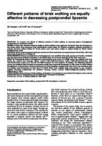
To verify if the predictions of the simulations are realizable, some further investigations were performed. First, data on the unstable state were gathered. A paraplegic subject was initially supported by two legs and a crutch. Knee extensors of both legs were stimulated to provide the support. One foot was in front of the other and the crutch on the side of the leading leg was lifted. The subject was then instructed to transfer the trailing leg forward by triggering the exion re ex. After lifting of the leg the subject entered the contralateral unstable state. OPTOTRAK measurement system was used to measure the trajectories of the chosen points on the body. Active markers were placed on the ankle, the knee, the hip and the shoulder on the side of the trailing leg. The measured horizontal displacement of the hip is shown in Fig. 9.a. The gure shows that the unstable state lasted approximately 1s and that during the unstable state the hip was displaced for 0.15m. The plantar exors were not used during the investigation. Apparently, the unstable state on Fig. 9.a was much longer than that predicted by the simulation. There are multiple reasons for the discrepancy: The investigation was done with the subject at rest. Furthermore, the subject has not been trained. In addition, dynamics of the gait and the use of plantar exors would arguably result in much shorter unstable state. Therefore, the measurements do not contradict the predictions of the simulation. Fig. 9. Horizontal displacement of the hip during the unstable state (a) and during the push-o� from the plantar
exors (b).
A second investigation was done to observe the action of the plantar exors during the stimulation. In this case, the subject used a walker instead of crutches. The subject was standing with one leg in front of the other. Knee extensors of both legs were stimulated. Then the stimulation of the plantar
exors of the trailing leg started. The same trajectories as in the previous case were measured. The horizontal displacement of the hip during the investigation is shown in Fig. 9.b. We can see that DRAFT
Z� EFRAN ET AL.: KINEMATIC MODELING OF FOUR-POINT WALKING PATTERNS
17
the activation of the plantar exors lasted approximately 0.5s and that the body was moved 0.06m in the horizontal direction. The horizontal displacement was moderate. However, considering the rather short step length of the FES-assisted gait (the step length often does not exceed the length of the foot), the e�ect of the stimulation of the plantar exors is signi cant. IV. Conclusion
Ambulation of SCI subjects can be obtained with a functional electrical stimulation but if FESassisted walking is to become an alternative to the wheelchair transportation, the energy e�ciency and the walking speed must be improved. Before a subject is able to walk with the FES he or she must go through several weeks of training to learn how to coordinate the actions during the gait. It is therefore not practical to study di�erent gait patterns directly on the subject. A kinematic model was developed to simulate a subject walking with crutches. The proposed changes to the existing walking pattern can thus be tested on the model before they are introduced into the rehabilitation program. A subject walking with crutches is modeled as a parallel structure. Inverse kinematic model of the parallel structure is used to compute the motion of the subject from the speci ed motion of the trunk and the positions of the endpoints of the legs and the crutches. The model was tested by simulating walking of a SCI subject assisted by the four-channel FES. Predictions of the model qualitatively agreed with the events during walking. The model was then used to investigate how various quadrupedal walking patterns could improve the existing gait. To obtain energy e�cient walking, the COB-trajectory during the simulation approximately followed the trajectory that can be observed during walking of healthy subjects. In this way, continuous and energy e�cient motion was obtained. Transfer between kinetic and potential energy is typical for walking of healthy subjects. During the single-support phase the subject can be viewed as an inverted pendulum. At the end of the swing, when the leg is placed on the ground, the kinetic energy accumulated during the swing phase is used for the push-o� phase and the propulsion of the body into a new swing of the inverted pendulum. Similar e�ect was anticipated during the simulation. In addition, unstable states were used in the walking patterns. During the unstable states the subject cannot statically maintain the balance and is forced into faster walking. From the simulation results, the muscle groups that are necessary for walking can be identi ed. In DRAFT
18
TO APPEAR: IEEE TRANS. ON SYSTEMS, MAN, AND CYBERNETICS, VOL. 26, NO. 11, NOV. 1996
this way, the stimulation sequences necessary to obtain such gait can be planned. Furthermore, the therapist can observe what events should trigger the start of the multichannel stimulation sequences delivered to the paralyzed lower limbs. The therapist can also use the simulation to develop a gait which is adequate for the physiological condition of the patient in the cases where the standard stimulation patterns cannot be used. The simulation results can serve to plan the sensory feedback that would provide the subject with better control over the motion. The computed angles in the joints can also directly serve as the input to the feedback controllers, if feedback schemes are used to generate the gait. Two walking patterns were identi ed as particularly suitable for the use with the FES. We have shown that they can be realized by proposing the FES sequences that would generate the motions predicted by the simulations. The two walking patterns were named ipsilateral and contralateral walking pattern, according to the position of the supporting leg and the crutch during the unstable state. The simulation results show that the existing four-channel FES is not adequate for the generation of more e�cient walking. However, if the stimulation of the plantar exors is added, both walking patterns can be generated with the FES. Stimulation of the plantar exors provides the push-o� from the trailing leg and easier transfer of the body weight to the leading leg. Consequently, the simulation predicts that smooth walking with the speed of 0.6m/s can be obtained. This is more than 4 times faster than the existing gait and approximately half the speed of healthy subjects. The contralateral walking pattern is the same as the pattern that humans use during crawling on the knees and the arms so it is expected that the time necessary to teach the subject to use such pattern would be shorter. The major de ciency of the model is that it cannot predict dynamic behavior during walking. Musculo-skeletal dynamic model would be necessary for such computation. Such a model would also predict muscle forces/torques during walking. Since forces/torques that can be generated with the FES are limited, such data would be useful to decide whether a walking pattern is suitable for implementation with the FES or not. Also the problem of stability is not addressed in our study. During the simulation the stability of walking is automatically guaranteed since the trajectories of the subject are prescribed. Musculo-skeletal models (see e.g. [16]) are di�cult to build because of the complicated structure of the human musculo-skeletal system. At present, no accurate dynamic model of the human musculoskeletal system is available. In addition, for our purposes the physiological state of a paraplegic DRAFT
Z� EFRAN ET AL.: KINEMATIC MODELING OF FOUR-POINT WALKING PATTERNS
19
patient with the applied electrical stimulation would have to be modeled. It is not realistic to expect that such models will be available in the near future. On the other hand, it is not clear whether dynamic model with a multitude of parameters would really provide additional insight into the events during the gait. In our opinion, the simplicity of the kinematic model o�sets majority of its drawbacks. Acknowledgments
This work was supported in part by the Slovene Ministry of Science and Technology, Ljubljana, Slovenia and the National Institute on Disability and Rehabilitation Research, Department of Education, Washington DC, USA.
DRAFT
20
TO APPEAR: IEEE TRANS. ON SYSTEMS, MAN, AND CYBERNETICS, VOL. 26, NO. 11, NOV. 1996
References [1] T. Bajd, A. Kralj, R. Turk, H. Benko, and J. S�ega, \The use of a four-channel electrical stimulator as an ambulatory aid for paraplegic patients", Physical Therapy, vol. 63, no. 7, 1983. [2] E. B. Marsolais and R. Kobetic, \Functional walking in paralyzed patients by means of electrical stimulation", Clinical Orthopedics, vol. 175, pp. 30{36, 1988. [3] R. Kobetic, \Advancing step-by-step", IEEE Spectrum, vol. 31, no. 10, pp. 27{31, Oct. 1994. [4] B. J. Andrews, R. H. Baxendale, R. Barnett, G. F. Phillips, J. P. Yamazaki, and P. A. Freeman, \Hybrid FES orthosis incorporating closed loop control and sensory feedback", J. Biomed. Eng., vol. 10, pp. 189{195, April 1988. [5] C. A. Phillips, \An interactive system of electronic stimulators and gait orthosis for walking in the spinal cord injured", Automedica, vol. 11, pp. 247{261, 1989. [6] A. Kralj and T. Bajd, Functional Electrical Stimulation: Standing and Walking after Spinal Cord Injury, CRC Press, Boca Raton, Florida, 1989. [7] A. Kralj, R. Turk, T. Bajd, M. S�tefan�ci�c, R. S�avrin, H. Benko, and P. Obreza, \FES utilization statistics for 94 patients", in Proc. of the Ljubljana FES Conference, Ljubljana, Slovenia, 1993, pp. 79{81. [8] T. Bajd, A. Kralj, and M. Z�efran, \Unstable states in 4-point walking", Journal of biomedical engineering, vol. 15, no. 2, pp. 159{162, Mar. 1993. [9] E. F. Fichter, \A Stewart platform-based manipulator: General theory and practical construction", The International Journal of Robotics Research, vol. 5, no. 2, Summer 1986. [10] K. H. Hunt, \Structural kinematics of in{parallel{actuated robot arms", ASME J. of Mech., Transm., and Aut. in Design, vol. 105, pp. 705{712, 1983. [11] D. A. Winter, Biomechanics of Human Movement, John Wiley & Sons, New York, 1979. [12] V. T. Inman, H. J. Ralston, and F. Todd, Human Walking, Williams & Wilkins, Baltimore, London, 1981. [13] T. Bajd and A. Kralj, \Four-point walking patterns in paralyzed persons", Basic and Applied Myology, vol. 1, no. 1, 1991. [14] T. Bajd, A. Kralj, T. Kar�cnik, R. S�avrin, and P. Obreza, \Signi cance of FES-assisted plantar exion during walking of incomplete SCI subjects", Gait & Posture, vol. 2, pp. 5{10, 1994. [15] E. Muybridge, The Human Figure in Motion, Dover Publications, Inc., New York, 1955. [16] G. T. Yamaguchi and F. E. Zajac, \Restoring unassisted natural gait to paraplegics via functional neuromuscular stimulation: A computer simulation study", IEEE Transactions on Biomedical Engineering, vol. 37, no. 9, September 1990.
DRAFT
Z� EFRAN ET AL.: KINEMATIC MODELING OF FOUR-POINT WALKING PATTERNS
21
Milo�s Z� efran received the B.E. and M.Sc. degrees in electrical engineering from the Faculty of Electrical
and Computer Engineering, University of Ljubljana, Slovenia in 1989 and 1992, respectively. In 1992 he received the B.Sc. degree in mathematics from the Faculty of Natural Sciences and Technology, University of Ljubljana, Slovenia. From 1992 he is a Ph.D. student in computer science at the University of Pennsylvania, Philadelphia, PA. He is currently a graduate fellow of the Institute for Research in Cognitive Sciences, University of Pennsylvania. His research interests include human motion analysis, robotics and optimal control.
Tadej Bajd (SM'90) graduated from the Faculty of Electrical Engineering, University of Ljubljana,
Slovenia in 1972, where he also obtained the M.Sc. and D.Sc. degrees in 1976 and 1979, respectively. He was a research assistant at Jozef Stefan Institute in Ljubljana and a visiting research fellow at University of Southern California, Los Angeles, CA and Strathclyde University, Glasgow, UK. He is presently a professor at the Faculty of Electrical and Computer Engineering, University of Ljubljana. Prof. Bajd is author and coauthor of more than 200 scienti c publications from the eld of biomedical engineering and coauthor of books on functional electrical stimulation and robotics. He was awarded several times with the Slovene national award for his scienti c achievements in the eld of functional electrical stimulation for paralyzed subjects. He is a member of the Council of ESEM and a member of IFMBE. Prof. Bajd is also a member of the editorial boards of two scienti c journals.
Alojz R. Kralj (F'90) received the diploma, M.Sc. and D.Sc. degrees in electrical engineering from the Faculty of Electrical Engineering, University of Ljubljana, Slovenia, in 1964, 1969 and 1970, respectively. He has been involved in the research in functional electrical stimulation since 1965 and has led the development of the Ljubljana methodology for FES-assisted standing and four-channel enabled gait in spinal cord injured patients. In 1973-74 he was a visiting professor at the University of Southern California and a research associate with the Rancho Los Amigos Hospital, Los Angeles, CA. From 1980 to 1986, he was a visiting professor at the Illinois Institute of Technology and Pritzker Institute of Medical Engineering, Chicago, IL. In 1986, he was a visiting professor at the Rush Medical College, Rush-Presbyterian-St. Luke's Medical Center, Department of Neurosurgery, Chicago, IL. He is currently a professor at the Faculty of Electrical and Computer Engineering, University of Ljubljana, Slovenia. At present he serves as the rector of the University. Prof. Kralj has published numerous papers and coauthored several books. He is a member of ISEK and ESEM and a member of the editorial boards of several major journals. For his work in functional electrical stimulation he has received several national and international awards. Prof. Kralj is a member of the Slovene Academy of Sciences and Arts.
DRAFT
22
TO APPEAR: IEEE TRANS. ON SYSTEMS, MAN, AND CYBERNETICS, VOL. 26, NO. 11, NOV. 1996
Figures
Photograph
Fig. 2. A paraplegic subject walking with the help of a four-channel electrical stimulator.
DRAFT
Z� EFRAN ET AL.: KINEMATIC MODELING OF FOUR-POINT WALKING PATTERNS
23
P1 P2 J1
xL
J2
zL
y
L
P3
J3
P4
J4
B1 B4
B2 B3 xR
zR
y
R
Fig. 3. The parallel linkage representing a paraplegic subject walking with crutches. DRAFT
24
TO APPEAR: IEEE TRANS. ON SYSTEMS, MAN, AND CYBERNETICS, VOL. 26, NO. 11, NOV. 1996
Pi
ui di Ji
φi
αi li
yR
βi γi
Bi xR
Fig. 4. Position of the leg-joint in space. DRAFT
zR
Z� EFRAN ET AL.: KINEMATIC MODELING OF FOUR-POINT WALKING PATTERNS
xR
25
zR
yR Fig. 5. Deformations of the trunk that were included in the model. DRAFT
26
TO APPEAR: IEEE TRANS. ON SYSTEMS, MAN, AND CYBERNETICS, VOL. 26, NO. 11, NOV. 1996
Fig. 6. Walking pattern corresponding to Fig. 6.
DRAFT
Z� EFRAN ET AL.: KINEMATIC MODELING OF FOUR-POINT WALKING PATTERNS
27
Fig. 7. Simulation of the existing walking pattern.
DRAFT
28
TO APPEAR: IEEE TRANS. ON SYSTEMS, MAN, AND CYBERNETICS, VOL. 26, NO. 11, NOV. 1996
Fig. 8. Simulation of the ipsilateral walking pattern.
DRAFT
Z� EFRAN ET AL.: KINEMATIC MODELING OF FOUR-POINT WALKING PATTERNS
29
Fig. 9. Simulation of the contralateral walking pattern.
DRAFT
30
TO APPEAR: IEEE TRANS. ON SYSTEMS, MAN, AND CYBERNETICS, VOL. 26, NO. 11, NOV. 1996
Horizontal displacement [m]
0.2
0.15
0.1
0.05
0 0
0.08
0.06
0.04
0.02
0
-0.02 0
Horizontal displacement [m]
0.5
0.2 0.4
1
0.6 1.5
0.8
2 Time [s]
1 Time [s]
2.5
1.2 1.4
3
1.6 3.5
1.8
4
2
Fig. 10. Horizontal displacement of the hip during the unstable state (a) and during the push-o� from the plantar
exors (b).
DRAFT