Nov 8, 2017 - RO] 8 Nov 2017 ... In [8] a design is suggested, which has six redundant dofs (3 in the platform .... 3Ng3(Q[12]N2g2 +L[56]Ng+A1[29]A2[8]) = 0,.
Kinematically Redundant Octahedral Motion Platform for Virtual Reality Simulations G. Nawratil and A. Rasoulzadeh
arXiv:1704.04677v2 [cs.RO] 8 Nov 2017
Institute of Discrete Mathematics and Geometry, Vienna University of Technology, Austria, e-mail: {nawratil,rasoulzadeh}@geometrie.tuwien.ac.at
Abstract. We propose a novel design of a parallel manipulator of Stewart Gough type for virtual reality application of single individuals; i.e. an omni-directional treadmill is mounted on the motion platform in order to improve VR immersion by giving feedback to the human body. For this purpose we modify the well-known octahedral manipulator in a way that it has one degree of kinematical redundancy; namely an equiform reconfigurability of the base. The instantaneous kinematics and singularities of this mechanism are studied, where especially ”unavoidable singularities” are characterized. These are poses of the motion platform, which can only be realized by singular configurations of the mechanism despite its kinematic redundancy. Key words: Stewart-Gough platform, Kinematic redundancy, Singularities, Motion simulator
1 Introduction The geometry of a Stewart-Gough (SG) platform is given by the six base anchor points Mi with coordinates Mi := (Ai , Bi ,Ci )T with respect to the fixed frame and by the six platform anchor points mi with coordinates mi := (ai , bi , ci )T with respect to the moving frame (for i = 1, . . . , 6). Each pair (Mi , mi ) of corresponding anchor points of the fixed body (base) and the moving body (platform) is connected by an SPS-leg, where only the prismatic joint (P) is active and the spherical joints (S) are passive. The distance between the centers of the two S-joints of the ith leg is denoted by ri . Note that for a SG platform, (Mi , mi ) 6= (M j , m j ) holds for pairwise distinct i, j ∈ {1, . . . , 6}. Moreover if two base points Mi and M j (resp. platform points mi and m j ) coincide, then we just write Mi, j (resp. mi, j ). A certain drawback of such 6-degree of freedom (dof) robotic platforms is the limitation of their singularity-free workspace. A promising approach for overcoming this problem is redundancy, where basically two types can be distinguished: (a) Actuation redundancy: One possibility is to add a 7th SPS-leg to the manipulator (e.g. [1, 2, 3]), but it should be noted that there exist dangerous locations for the attachments m7 and M7 (cf. [4]), which do not result in a reduction of singularities. Clearly more than one SPS-leg can be attached, but we have to 1
2
G. Nawratil and A. Rasoulzadeh
keep in mind that every extra leg may yields a restriction of the workspace due to leg constraints and leg interference [1]. Moreover [5] pointed out that this so-called branch redundancy1 causes internal loads, whose control increases considerably the complexity and costs. (b) Kinematic redundancy: This can be achieved by attaching active joints in a way that the geometry of the platform or base (or both) can be modified. Therefore they are also known as reconfigurable manipulators2 of SG type. In [8] a design is suggested, which has six redundant dofs (3 in the platform and 3 in the base). The weak points of this so-called dodekapod are that on the one hand additional mass/inertia (motor of active joints) is added to the platform and that on the other hand passive prismatic joints are used, which are difficult to implement in practice (cf. [5]). Not faced with these points of criticism are the designs suggested in [9, 10], where one base point is traced on a circle (realized by an extra R-joint [9]) or a straight line (realized by an extra P-joint [10]). We complete this review by noting a different approach to kinematic redundancy; namely the usage of parallel redundant legs introduced in [5]. Another advantage of approach (b) over (a) beside the already mentioned ones above is that (a) increases the workspace only by removing singularities, but (b) additionally enlarges the workspace itself due to the reconfigurability of the anchor points. Further differences between both concepts are pointed out at the end of Section 2.1.
1.1 Aim and basic concept Within the Doctoral College ”Computational Design” of the Vienna University of Technology, we are interested amongst other things in the optimization of motion platforms of SG type for virtual reality (VR) application of single individuals. In detail, we want to mount an omni-directional treadmill onto the motion platform (cf. Fig. 2) in order to improve VR immersion by giving feedback to the human body (e.g. simulating slopes, earthquakes, . . . ). There are different locomotion systems commercially available; e.g. Cyberith Virtualizer (cyberith.com), Omni Virtuix (www.virtuix.com), SpaceWalkerVR (spacewalkervr.com), Kat Walk (www.katvr.com) and Wizdish ROVR (www.wizdish.com). Due to safety reasons we prefer a system where the individuals are fixed inside a hip-ring by belts and straps. Thus we are only left with the Omni Virtuix and the Cyberith Virtualizer. We favor the latter system as it has one more dof, which allows to kneel/crouch/sit down or even to jump up, and a flat base plate with a suitable friction coefficient for simulating slopes. Contrary, the Omni Virtuix’s base has a very low friction (too slippery for slope simulations) and a concave shape. 1
A further possibility to imply actuation redundancy in a SG platform is to replace passive joints by active ones. No attempts to this so-called in-branch redundancy are known to the authors. 2 The modules in a variable geometry truss (VGT) can also be seen as reconfigurable manipulators (cf. [6, Fig. 9]). In this context see also [7], where a VGT is combined with a SG structure.
Kinematically Redundant Octahedral Motion Platform for Virtual Reality Simulations
3
m3 = m4 m5 = m6 m1 = m2
M4 = M5 M2 = M3 M6 = M1 Fig. 1 (Left) SG manipulator with planar semi-hexagonal base and platform. (Right) Octahedral SG manipulator, which is also known as MSSM (Minimal Simplified Symmetric Manipulator) in the literature (e.g. [11]). This parallel robot is characterized by: m1 = m2 , m3 = m4 , m5 = m6 , M2 = M3 , M4 = M5 , M6 = M1 . Therefore all attachments are double spherical joints, which form a triangle in the platform and the base. Moreover we assume that both triangles are equilateral.
All currently offered 6-dof motion simulators of SG type have a planar semihexagonal base and platform (see Fig. 1 (left)). This design is preferred over the so-called octahedral SG manipulator (see Fig. 1 (right)) as it avoids double S-joints, which have a lot of disadvantages regarding costs, stiffness and joint-range. Nevertheless we focus within this concept study on the octahedral design (as many other academic studies e.g. [7], [9, Section 4], [11, 12, 13, 14, 15, 16, 17], . . . done in the past), due to its kinematic simplicity. But this application-alien abstraction can also be brought back to real-world solutions as pointed out in Section 3. Due to the arguments given above we want to use concept (b) of kinematic redundancy in order to increase the singularity-free workspace of the octahedral manipulator. Having our practical application in mind, the resulting reconfigurable manipulator should still be of kinematic simplicity (the symmetry of the manipulator should not be destroyed) and cheap ; i.e. we want to get by with standard components (less or even no expensive custom products). Taking all these requests under consideration, we came up with the design illustrated in Fig. 2. We use three additional active P-joints (green), which are driven simultaneously by only one motor mounted at the center of the base. Therefore the base triangle remains equilateral during the reconfiguration process. The proposed manipulator can be seen as a combination of a SG hexapod and a so-called hexaglide (e.g. [18]). As the linear sliding of the points Mi,i+1 along the lines gi,i+1 can be realized by parallel guiding rails, the whole structure can still be built very stiff with a high load-carrying capacity. Moreover the complete additional equipment for the performance of the reconfiguration (motor, rails, . . . ) is placed on the resting base such that the legs and platform are not stressed by additional mass/inertia. Remark 1. Let us assume that the three additional prismatic joints are passive instead of active (but still coupled). Moreover we lock the six P-joints of the legs. Then the base has in each pose of the manipulator at least a 1-dimensional self-motion with respect to the platform, due to the equiform reconfigurability of the base. These relative motions (of the base with respect to the platform) are studied in [16]. �
4
G. Nawratil and A. Rasoulzadeh
hip-ring Virtualizer’s base
motor -box
Fig. 2 Octahedral SG manipulator with a 1-dof kinematic redundancy (equiform reconfigurability of the base) and a Virtualizer mounted on top. In practice one S-joint of an SPS-leg is replaced by an universal joint (U), thus all double S-joints can be replaced by concentric SU-joints (blow-ups).
2 Instantaneous kinematics and singularities The ith leg of the 7-dof reconfigurable manipulator fulfills the basic relation ri (τ)2 = kni (τ) − Mi (τ)k2 , where ni is the coordinate vector of mi with respect to the fixed system. Differentiation with respect to the time τ yields: ˙ i) ri r˙i = (ni − Mi )(n˙ i − M
⇒
˙ i ), r˙i = li (n˙ i − M
(1)
where li is the unit-vector along the ith leg (pointing from the base point to the platform point). As the velocity of ni can be expressed in terms of the instantaneous b) of the platform with respect to the fixed system by n˙ = q b + q × ni we screw (q, q get: ˙ i = li q b + li (q × ni ) ⇒ r˙i + gg b +bli q, r˙i + li M ˙ i li = li q (2) where gi is the unit-vector along gi , g˙ the velocity along gi and bli the moment vector of the ith leg. Note that (li ,bli ) are the spear coordinates of the ith leg. Thus we end up with: T T bl r˙1 g1 l1 l1 � � 1 q .. .. .. .. . with J := . (3) . + g˙ . = J b . q blT lT r˙6 g6 l6 6
6
This equation relates the velocities r˙1 , . . . , r˙6 , g˙ of the active P-joints with the instanb) of the platform. If we fix all prismatic joints the left side of taneous screw (q, q Eq. (3) equals the zero vector. Then an infinitesimal motion of the platform is only possible if the Jacobian matrix J of the octahedral manipulator is singular; which is well studied problem (e.g. [13, 15] or [11, pages 202–204]).
Kinematically Redundant Octahedral Motion Platform for Virtual Reality Simulations
5
2.1 Unavoidable singularities Definition 1. If for a given pose of the platform the corresponding configuration of the mechanism is singular for all kinematically redundant dofs, we call this singular pose of the platform an ”unavoidable singularity”. To the best knowledge of the authors there are no studies on ”unavoidable singularities” in the literature, with the following two exceptions: • In [5, Section V(D)] it is stated that for the octahedral manipulator with three redundant legs ”any Cartesian pose of the moving platform can be reached with a non-singular configuration of the mechanism”. Moreover, it is ”conjectured that this result can be extended to mechanisms whose spherical joints on the platform do not coincide by pairs”, but this is disproved in Appendix A. • For the kinematically redundant SG manipulator of [9], there exist up to 40 positions of the platform causing an unavoidable singularity for a given orientation (cf. [9, Section 4.4.2]). Some special orientations causing a higher-dimensional set of unavoidable singularities were studied in [9, Section 4.4.3]. For the proposed mechanism of the paper at hand, we can chose an appropriate scaling factor and coordinate systems in the fixed and moving space in a way that: m1,2 = (1, 0, 0)T ,
√ T 3 2 , 0) , √ M6,1 = g( 12 , − 23 , 0)T ,
m3,4 = (− 12 ,
T
M4,5 = g(−1, 0, 0) ,
√ T 3 2 , 0) , √ M2,3 = g( 12 , 23 , 0)T ,
m5,6 = (− 12 , −
(4) (5)
hold, where g > 0 is the reconfiguration variable (= radius of the circumcircle of the equilateral base triangle). Based on this coordinatization we can compute the entries of J by (li : bli ) := (Rmi + s − NMi : Mi × li ) with the rotation matrix 2 e0 + e21 − e22 − e23 2(e1 e2 − e0 e3 ) 2(e1 e3 + e0 e2 ) R = 2(e1 e2 + e0 e3 ) e20 − e21 + e22 − e23 2(e2 e3 − e0 e1 ) , 2(e1 e3 − e0 e2 ) 2(e2 e3 + e0 e1 ) e20 − e21 − e22 + e23 N = e20 + e21 + e22 + e23 and the translation vector s = (x, y, z)T . Note that (e0 : e1 : e2 : e3 ) 6= (0 : . . . : 0) are the so-called Euler parameters. Then the singularity condition Σ : det J = 0 has the following structure: √ Σ : 83 3Ng3 (Q[12]N 2 g2 + L[56]Ng + A1 [29]A2 [8]) = 0, (6) where the number in the brackets gives the number of terms. Note that Q and A2 depend linearly on x, y, z and that L and A1 are polynomials in z2 , xz, yz, x, y, z. Theorem 1. The unavoidable singularities of the 1-dof kinematic redundant octahedral manipulator of SG type studied in the paper at hand are listed in the following table containing the positions of the unavoidable singularities in the 3rd column for the orientations given in the 2nd column and the 4th column gives the dimension of the singularity set:
6
G. Nawratil and A. Rasoulzadeh row
orientation
position
dim
1 2 3 4
e1 = e2 = 0 e1 = e2 = 0, e0 = ±e3 e0 = e3 = 0 e0 = ±e3 , e2 = ∓e1
z=0 arbitrary arbitrary z = 2e1 e3
3 3 4 3
5 6 7
e0 = ±e3 , e2 = ∓e1 e0 = ±e3 , e2 = ∓e1 √ e0 = e3 , e1 = (2 ± 3)e2 √ e0 = e3 , e1 = (2 ± 3)e2 √ e0 = e3 , e1 = (2 ± 3)e2 √ e0 = −e3 , e1 = (−2 ± 3)e2 √ e0 = −e3 , e1 = (−2 ± 3)e2 √ e0 = −e3 , e1 = (−2 ± 3)e2
z = − 3 3 e1 1 , x = 0 z = −4e1 e3 , y = ±2(e21 − e23 ) 4e2√ e3 z = 1∓ 3
8 9 10 11 12
e (2e2 +2e2 ±y)
√ 16e22 ±8e22 3+y−4e23 √ √2 e3 , z = ±8e ± 3 √3−1 2 2 2 √ 2e (e +4e2 ±2e2 3−y) √ x = ∓y 3, z = 3 3 e (1± 3) 2 √2 e3 z = ∓4e 3−1 √ 16e2 ∓8e2 3−y−4e23 8e2√ e3 , z = 1± x = 2 ∓2 √3 3 √ √ 2e (e2 +4e2 ∓2e22 3+y) x = ∓y 3, z = 3 3e (±2√3−1) 2
x=
13 e0 = e2 = 0 14 e1 = e3 = 0 15 e0 = e1 = 0 16 e2 = e3 = 0 17 e0 e1 + e2 e3 = 0 18 e22 e23 − 3e22 e20 + 8e2 e1 e0 e3 − 3e21 e23 + e21 e20 = 0 19 20 21 22
e0 =
e2 e3 e1
e0 = − e1e2e3 arbitrary arbitrary
z = e1 e3 z = −e0 e2 y=z=0 y=z=0 z of Eq. (7) z of Eq. (7) y = 2e2
e21 +e23 e1 ,
z=
e2 −e2 = 2e1 3e2 2 ,
e3 (e41 −6e21 e22 +e42 ) e1 (e21 −e22 )
2 2 3 2 2 3 2 2 3 3 2 2 4 4 3
y 3 z = −4e1 e3 z of Eq. (7), x of Eq. (8), y of Eq. (9) 3 z of Eq. (7), x of Eq. (10), y of Eq. (11) 3
with z=
(e20 + e23 )(e31 e3 − 3e1 e22 e3 − 3e21 e2 e0 + e32 e0 ) , (e23 − e20 )(e22 + e21 )
(7)
x=
(e20 + e23 )(e23 e21 − e23 e22 − 4e1 e2 e0 e3 − e41 + 6e22 e21 − e42 − e20 e21 + e20 e22 ) , 2(e22 + e21 )(e20 − e23 )
(8)
y=
(e23 + e20 )(e1 e2 e23 + e21 e3 e0 − e22 e3 e0 + 2e31 e2 − 2e1 e32 − e1 e2 e20 ) , (e22 + e21 )(e23 − e20 )
(9)
x=
e43 e21 − e43 e22 + 3e23 e21 e22 − e23 e42 + 2e3 e0 e31 e2 + 2e3 e0 e1 e32 − e41 e20 + 3e21 e22 e20 − e40 e21 + e40 e22 , (10) (e22 + e21 )(e20 − e23 )
y=
2e43 e1 e2 + 3e23 e31 e2 + e3 e42 e0 − e23 e1 e32 − e3 e0 e41 − 2e40 e1 e2 + e20 e31 e2 − 3e20 e1 e32 . (e22 + e21 )(e23 − e20 )
(11)
Proof. For an unavoidable singularity the conditions Q = L = A1 A2 = 0 have to hold. This system of equations can be solved explicitly3 for x, y, z. The detailed case study yielding the above table is presented in Appendix B. Note that for a given orientation the positions are (unions of) affine subspaces of R3 . � 3
In contrast to [9], where the unavoidable singularities are obtained as the numeric solution of an univariate polynomial of degree 40.
Kinematically Redundant Octahedral Motion Platform for Virtual Reality Simulations start
7
end
g
min start
singularities
max
motion parameter
end
start
end
Fig. 3 Singularity avoidance by kinematical redundancy: In the upper left picture the given motion of the platform between the start- and end-pose is displayed. Without reconfiguration of the base the manipulator will pass two singular configurations, which are highlighted in red. They correspond to the two intersection points of the blue horizontal line and the red singularity curve in the diagram in the upper right corner. One can avoid these singularities by performing a reconfiguration of the base indicated by the dashed line in the diagram, but then there is a collision of legs in the end-pose, which is illustrated in the lower left picture. The green parabola in the diagram corresponds to a solution, which is free of leg-interference and singularities. The robot-configuration of this solution with g = max is displayed in the lower right picture. An animation can be downloaded from: http://www.geometrie.tuwien.ac.at/nawratil/reconfiguration.gif
As the unavoidable singularities are low-dimensional varieties (cf. Theorem 1) in the 6-dimensional workspace, they can always be bypassed during path-planning. But this does not imply the existence of a singularity-free path as the singularity variety is a hypersurface in the mechanism’s configuration space.4 Due to topological reasons two points of the configuration space can be separated by this hypersurface. In contrast, actuation redundancy reduces the dimension of the singularity variety by the number of redundant dofs (cf. [1, Section 3]) and therefore a singularity can always be avoided during path-planning. But in the case of a given path of the platform, kinematic redundancy is superior to actuation redundancy, as kinematically redundant dofs can be used to avoid singularities (if possible) and to increase the performance of the manipulator during the 4
For our mechanism this is a 7-dimensional space, as a mechanism configuration is given by the pose of the platform (6 dofs) and by the size of the base triangle (1 dof).
8
G. Nawratil and A. Rasoulzadeh
Fig. 4 Axonomatic view (left) and top view (right) of a kinematic equivalent mechanism to Fig.2. On this design further studies (e.g. construction of a small scale prototype, optimal reconfiguration of the base for a given motion, . . . ) are based.
prescribed motion (cf. Fig. 3). The study of the optimal reconfiguration of the base of the proposed mechanism during a given motion is dedicated to future research. Remark 2. Note that a so-called modular parallel robot [19] also changes its geometry with respect to a given end-effector motion, but there is no reconfiguration of the robot’s base/platform during the motion of the end-effector. �
3 Conclusion This paper contains a concept study of an octahedral SG manipulator with one degree of kinematic redundancy (equiform reconfigurability of the base) for VR simulations of single individuals (see Fig. 2). In a side-note we also proposed SU-joints (see Fig. 2) as an alternative to the problematic double S-joints within the octahedral structure. Clearly a deeper study of these SU-joints (regarding stiffness, joint-range, dynamic behavior, . . . ) has to be done in order to judge their applicability. Another possibility is the substitution of all double S-joints by double U-joints (e.g. see [12, Fig. 16] and [14, Section 4]) and to replace the P-joints by cylindrical joints, with a passive rotation and an active translation component. But we pursue another strategy for the technical realization; namely the usage of a design which is totally free of double joints but kinematically equivalent to the octahedral manipulator (cf. [20]). Therefore the resulting design illustrated in Fig. 4 can be built with standard components; i.e. without expensive custom products. Acknowledgements The first author is supported by Grant No. P 24927-N25 of the Austrian Science Fund FWF. The second author is funded by the Doctoral College ”Computational Design” of TU Vienna. Moreover the authors want to thank Hannes Kaufmann of the ”Center for Geometry and Computational Desgin” at TU Vienna for fruitful discussions on VR motion simulations.
Kinematically Redundant Octahedral Motion Platform for Virtual Reality Simulations
9
References 1. Dasgupta, B., Mruthyunjaya, T.S.: Force redundancy in parallel manipulators: theoretical and practical issues. Mech. Mach. Theory 33(6) 727–742 (1998) 2. Zhang, Y., Gong, J., Gao, F.: Singularity elimination of parallel mechanisms by means of redundant actuation. 12th IFToMM World Congress, Besancon, France, June 18–21 (2007) 3. Cao, Y., Zhou, H., Li, B., Long, S., Liu, M.: Singularity elimination of Stewart parallel manipulator based on redundant actuation. Adv. Mat. Res. 143-144 308–312 (2011) 4. Husty, M., Mielczarek, S., Hiller, M.: Redundant spatial Stewart-Gough platform with a maximal forward kinematics solution set. Advances in Robot Kinematics: Theory and Applications (J. Lenarcic, F. Thomas eds.), pages 147–154, Kluwer (2002) 5. Schreiber, L.T., Gosselin, C.: Kinematically Redundant Spatial Parallel Mechanisms for Singularity Avoidance and Large Orientational Workspace. Trans. Robot. 32(2) 286–300 (2016) 6. Merlet, J.-P.: Redundant parallel manipulators. Lab. Robotics Automat. 8(1) 17–24 (1996) 7. Stoughton, R.S., Salerno, R., Canfield, S., Reinholtz, C.: A redundant, 6-dof parallel manipulator structure with improved workspace and dexterity. Proc. of the 5th Int. Symposium on Robotics and Manufacturing, Maui, Hawai, USA, August 14-18 (1994) 8. Bande, P., Seibt, M., Uhlmann, E., Saha, S.K., Rao, P.V.M.: Kinematics analyses of Dodekapod. Mech. Mach. Theory 40(6) 740–756 (2004) 9. Wang, J., Gosselin, C.M.: Kinematic Analysis and Design of Kinematically Redundant Parallel Mechanisms. J. Mech. Design 126 109–118 (2004) 10. Kotlarski, J., Heimann, B., Ortmaier, T.: Influence of kinematic redundancy on the singularityfree workspace of parallel kinematic machines. Front. Mech. Eng. 7(2) 120–134 (2012) 11. Merlet, J.-P.: Parallel Robots. Second Edition, Springer (2006) 12. Fichter, E.F.: A Stewart Platform-Based Manipulator: General Theory and Practical Construction. Int. J. Robot. Res. 5(2) 157–182 (1982) 13. Hunt, K.H., McAree, P.R.: The Octahedral Manipulator: Geometry and Mobility. Int. J. Robot. Res. 17(8) 868–885 (1998) 14. Lee, J., Duffy, J., Hunt, K.H.: A Practival Quality Index Based on the Octahedral Manipulator. Int. J. Robot. Res. 17(10) 1081–1090 (1998) 15. Downing, D.M., Samuel, A.E., Hunt, K.H.: Identification of the Special Configurations of the Octahedral Manipulator using the Pure Condition. Int. J. Robot. Res. 21(2) 147–159 (2002) 16. Hamdoon, F. M., Abdel-All, N. H.: An Investigation of an Octahedral Platform Using Equiform Motions. J. Geom. Graphics 8(1) 33–39 (2004) 17. Jiang, Q., Gosselin, C.M.: Geometric Optimization of the MSSM Gough-Stewart Platform. J. Mech. Robot. 1 031006 (2009) 18. Hebsacker, M.: Entwurf und Bewertung Paralleler Werkzeugmaschinen – das Hexaglide. Dissertation, ETH Z¨urich (2000) 19. Merlet, J.-P.: Determination of the optimal geometry of modular parallel robots. Proc. of the IEEE Int. Conference on Robotics and Automation 1 1197–1202 (2003) 20. Rojas, N., Borras, J., Thomas, F.: The Octahedral Manipulator Revisited. Proc. of the IEEE Int. Conference on Robotics and Automation, Saint Paul, Minnesota, USA, May 14-18 (2012)
10
G. Nawratil and A. Rasoulzadeh
mi−1
mi a
Mi−1
Mi,b
Mi,a
mi−1
mi
Mi,b
Mi,a Mi−1 Fig. 5 Non-redundant legs are displayed in black and redundant ones are illustrated in red. In the upper row the axonometric views and in the lower row the top views of a non-singular configuration (left) and an unavoidable singularity (right), respectively, are given.
Appendix A As already mentioned in the first bullet of Subsection 2.1, the authors of [5] stated in Section Section V(D) that for the octahedral manipulator with three redundant legs ”any Cartesian pose of the moving platform can be reached with a non-singular configuration of the mechanism”.5 Moreover, it is ”conjectured that this result can be extended to mechanisms whose spherical joints on the platform do not coincide by pairs”. In this section we construct a counter example to the conjecture. According to Assumption 1 of [5, Section V(D)] the base anchor points have to fulfill the following property: Mi,a , Mi,b , Mi−1 are collinear for i = 1, 3, 5 (mod 6),
(12)
where Mi−1 is the base point of a non-redundant leg and Mi,a , Mi,b denote the two base anchor points of a redundant leg. The geometric structure of the redundant leg 5
This is only true under Assumption 2 of [5, Section V(D)]. Without this assumption all poses where the platform and the base are coplanar are ”unavoidable singularities”.
Kinematically Redundant Octahedral Motion Platform for Virtual Reality Simulations
11
can be seen in Fig. 5 (upper left). It should only be noted that the orange cylinders represent passive rotational joints and that the 3 gray bars linked by this joint are coplanar. We start with a semi-hexagonal platform parallel to the base plane δ . Then we determine the corresponding base point(s) of m j as follows: We construct a plane ε j orthogonal to δ , which touches the circumcircle of the semi-hexagonal platform in m j . The intersection line of ε j and δ is illustrated in Fig. 5 (left) in red (for j = 1, 3, 5) and blue (for j = 2, 4, 6), respectively. Under consideration of (12) we select the base point(s) on these intersection lines. Then we rotate the platform by −90 degrees about the center axis a and end up with a singular configuration (so-called Fichter singularity [12]) illustrated in Fig. 5 (right). It can easily be checked that this is an unavoidable singularity.
Appendix B We split the proof of Theorem 1 into two subsections. In the first one very special cases are discussed and in the second one we attack the general case.
Special cases 1. Within this first item we study all cases where at least two of the four Euler parameters are zero. a. e1 = e2 = 0: Then Q and L are fulfilled identically and we remain with A1 A2 = 0, which factors into z3 (e20 + e23 )(e0 − e3 )(e0 + e3 ) = 0.
b. c.
d. e. f.
(13)
For z = 0 the legs are in a field of lines, whose carrier plane is the base (⇒ row 1 of the table given in Theorem 1). For e0 = ±e3 we get the Fichter singularity (cf. [12]); i.e. rotation of the platform by ±90◦ about the z-axis (⇒ row 2). e0 = e3 = 0: This is already a singular configuration (⇒ row 3), which is not of practical relevance as the platform is upside down. e0 = e2 = 0 and e1 e3 6= 0: It can easily be seen that Q = L = A1 A2 = 0 can only hold for z = e1 e3 (⇒ row 13). The lines are in a singular linear line complex. e1 = e3 = 0 and e0 e2 6= 0: Analogous considerations as in item (1c) yield z = −e0 e2 (⇒ row 14). The lines are in a singular linear line complex. e0 = e1 = 0 and e2 e3 6= 0: It is not difficult to verify that the unavoidable singularities are given by y = z = 0 (⇒ row 15). e2 = e3 = 0 and e0 e1 6= 0: Analogous considerations as in item (1e) yield y = z = 0 (⇒ row 16).
12
G. Nawratil and A. Rasoulzadeh
2. e0 = e3 6= 0: In this case Q factors into √ √ 2e33 (e1 + e2 )(e1 − 2e2 − 3e2 )(e1 − 2e2 + 3e2 ).
(14)
We remain with the following three cases: a. e2 = −e1 and e3 6= 0: Now we get L = 4e21 e3 (z − 2e1 e3 )(e1 z + 2e21 e3 + 2e33 + ye3 ), A1 A2 = 4xe1 e3 (z − 2e1 e3 )(2e1 e3 y − e23 z + e21 z),
(15)
thus the following cases can occur: i. e1 = 0: We get again the Fichter singularity. ii. z = 2e1 e3 and e1 6= 0: In this case all legs intersect a line and therefore they belong to a singular linear line complex (⇒ row 4, upper sign). iii. e1 z + 2e21 e3 + 2e33 + ye3 = 0 and (z − 2e1 e3 )e1 6= 0: We can solve this equation for z and then A1 A2 can only vanish without contradiction for x = 0 (⇒ row 5, upper sign) or y = 2e21 − 2e23 (⇒ row 6, upper sign). Therefore √ we get two lines in the position space. b. e1 = (2 + 3)e2 and (e1 + e2 )e3 6= 0: By inspecting L and A1 A2 in a similar way as done in very detail in item (a) we get the following solutions: 4e2 e3 i. z = − √ : In this case all legs intersect again a line and therefore they 3−1 belong to a singular linear line complex (⇒ row 7, upper sign). √ 16e2 +8e2 3+y−4e2
8e2 e3 3 ii. x = 2 2√3 and z = √ : For a given orientation we get a 3−1 line in the position space (⇒ row√8, upper sign). √ 2e (e2 +4e2 +2e2 3−y) : For a given orientation we get iii. x = −y 3 and z = 3 3 e (√2 3+1)2 2 again √ a line in the position space (⇒ row 9, upper sign). c. e1 = (2 − 3)e2 and (e1 + e2 )e3 6= 0: Exactly the same computations as in item (b) yield the solutions given in the rows 7, 8, and 9, but now for the lower signs.
3. e0 = −e3 6= 0: This is the same discussion as in item (2). The resulting solutions are given in the rows 4, 5 and 6, but now for the lower signs, and in the rows 10, 11 and 12 (upper and lower signs).
General case We start by solving Q = 0 for z which yields Eq. 7. The denominator vanishes only for the special cases (1a), (1b), (2) and (3), respectively. We insert this expression for z into L = 0 and A1 A2 = 0 and consider the greatest common divisor of the resulting numerators, which reads as follows: (e0 e1 + e2 e3 )(e22 e23 − 3e22 e20 + 8e2 e1 e0 e3 − 3e21 e23 + e21 e20 ).
(16)
Kinematically Redundant Octahedral Motion Platform for Virtual Reality Simulations
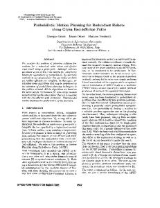
Fig. 6 For the orientation given by the Euler parameters e0 = √ − 16525105
√ 4 105 175 ,
e1 =
√ 105 21 ,
e2 =
13
√ 8 105 105 ,
the unavoidable singularities of row 21 and row 22 are illustrated in the left and e3 = 148327 12304 right figure, respectively. The position of row 21 equals x = − 130830 , y = − 66032 65415 , z = 13083 and 40969 85772 12304 the one of row 22 is given by x = 65415 , y = − 65415 , z = 13083 .
If one of these two factors vanish we get the solutions given in the rows 17 and 18, respectively. The remaining factor of L has 40 terms and is linear in x. As the coefficient of x equals 2(e22 + e21 )(e0 − e3 )(e0 + e3 )(e0 e1 − e2 e3 )(e0 e2 + e1 e3 )
(17)
we have to distinguish the following three cases: 1. e0 e1 − e2 e3 = 0: If one of the ei ’s is equal to zero, this equation implies that also a second one has to vanish. Therefore we get one of the already discussed special cases (1a,b,c,d). As a consequence we can set e0 = e2e1e3 . Then the numerator of L simplifies to e43 (e1 − e2 )(e1 + e2 )(e22 + e21 )3 (2e2 e21 − ye1 + 2e2 e23 ).
(18)
As e1 = ±e2 implies e0 = ±e3 we can only end up with a case studied in the special case (2) and (3), respectively. Therefore we only remain with 2e2 e21 − ye1 + 2e2 e23 = 0 which implies row 19. 2. e0 e2 + e1 e3 = 0: For the same reasons as in item (1) of the general case we can set e0 = − e1e2e3 . Analogous considerations imply the condition 2e1 e22 − 2e1 e23 + ye2 = 0 resulting in row 20. 3. (e0 e1 − e2 e3 )(e0 e2 + e1 e3 ) 6= 0: In this case we can solve L = 0 for x. Plugging the resulting expression into A1 A2 yields two factors, which are linear in y. They imply the solutions given in row 21 and 22, which are illustrated in Fig. 6. End of all cases.
�