such as underwater rovers [1], the tether dynamics must be incorporated into the ... The specific area of tethered space robots has been explored by Nohmi et al., ...
KINEMATICS AND DYNAMICS OF TETHERED SPACE MANIPULATORS Ming-Yin Priscilla Woo* and Arun K. Misra† Department of Mechanical Engineering, McGill University ABSTRACT Kinematics and dynamics of a rigid two-link robot manipulator connected to a spacecraft by a rigid, straight tether are considered. This system is different from a conventional four-joint system since in most practical situations, torques can be applied at only two of the joints. A two-point boundary value problem is solved to determine the torques required to move the end-effector from one arbitrary position to another. INTRODUCTION Space manipulators have existed for more than two decades, assisting astronauts in many endeavours. Their operations can significantly benefit from a longer reach of the robotic arm, which can be accomplished with little mass and fuel costs by the addition of a tether. This also allows for the arm to operate at a greater distance from the spacecraft, thus reducing the risk of collision. On the other hand, the tether also brings along more dynamic complexities. Furthermore, unlike a rigid manipulator link, applying torques at the ends of the tether involves additional considerations. Many robotic systems are attached to command posts with cables, through which information such as navigation directives or collected data is communicated. Usually, the effect of a slack tether on the rest of the robotic system is minimal, but in some cases, such as underwater rovers [1], the tether dynamics must be incorporated into the model. The specific area of tethered space robots has been explored by Nohmi et al., covering aspects such as the casting [2] and trajectory planning [3] of such systems. In this study, a model is developed to investigate the kinematics and dynamics of a tether-connected space manipulator system. Specifically, the end-effector trajectory and the tether tension are examined under varying conditions. In addition, a method to determine a feasible trajectory between two desired end-effector positions is presented. * †
M. Eng. Student Professor and Chair
link 1: m1 , a1
φ4 φ3 mb
E
ma
mc
tether: mt , l link 2: m2 , a2
φ2 moff circular orbit
local vertical
b
φ1
yo
zo
xo
C
spacecraft: I px , I py , I pz
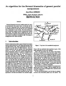
Figure 1: Model of the System DYNAMICAL MODEL Description of the System The system studied is composed of a two-link robotic manipulator, a tether and a spacecraft as illustrated in Figure 1. The links of the robot arm are modelled as rigid rods and the tether is assumed to be straight and rigid. A point mass is located at each joint in the system and at the end-effector. The centre of mass of the system C traces a circular orbit of radius Rc around Earth and is considered to be coincident with the centre of mass of the spacecraft. The spacecraft has mass m p and principal moments of inertia, I px , I py and I pz . The tether is of mass mt and constant length l and it is anchored at an offset from the centre of mass of the spacecraft as indicated by vector b . The link connected to the tether, that is link 1, has mass m1 and length a1 , and the link with the end-effector, link 2, has mass m2 and length a2 .
There are point masses located at both attachment points of the tether, at the joint of the robot arm and at the end-effector. The one at the anchor point of the tether (on the spacecraft) has mass moff , while at the other end of the tether there is a mass ma . The point mass at the elbow of the manipulator has mass mb and the one located at the endeffector, the payload at point E, has mass mc . Only planar motion of the system is considered in this study. The angles φ1 , φ2 , φ3 and φ4 reflect the motion at joints 1, 2, 3 and 4 respectively. They also characterize the orientation of the offset vector b , the tether and links 1 and 2 respectively in relation to the local vertical indicated by the xo -axis.
Formulation of the Equations of Motion The equations of motion are too lengthy to be stated here and can be found in detail in [4]. Developed using Lagrange’s Method, they can be summarized in the form of:
A ( q ) q + f ( q, q ) = Q ,
(1)
where A is a 4x4 matrix function of q and f is a 4x1 vector function of q and q . Both A and f are also dependent on the mass and length parameters of the system. The T generalized coordinates vector is chosen to be q = {φ1 φ2 φ3 φ4 } and the associated T generalized forces vector Q = {Q1 Q2 Q3 Q4 } is a function of the non-conservative external torques that cause the motion prescribed by q , namely:
τ1 − τ 2 τ −τ Q= 2 3 , τ3 −τ 4 τ4
(2)
where τ i is the torque applied at each joint to cause the angular displacement indicated by q . All other external influence is considered to be negligible.
FEASIBLE TRAJECTORIES WITH TORQUE CONSTRAINTS Constraint Equations To closely model a realistic tethered space manipulator, a constraint is added to prevent the rigid rod representing the tether from sustaining any arbitrary torque. This is
desired since applying bending moments to a tether is not very practical. Hence, we restrict the torques applied at the tether attachment points to zero, that is, τ 2 = τ 3 = 0 . From these constraints, the following system of two equations is obtained: A*q + f * = 0 ,
(3)
corresponding to the second equation and the sum of the third and fourth equations of the system described in Eq. (1). Therefore, from Eq. (3), the joint angular acceleration vector can be derived as: q = − ( A* ) f * , +
where ( A* ) = AT ( AAT ) +
−1
(4)
is the pseudo-inverse of A* .
The expression obtained for q from this equation corresponds to the minimum norm, least squares solution, i.e. the solution that has the smallest value of q that minimizes the error norm A*q + f * . Note that this particular value of q corresponds to only one solution among the infinite solution space of the underdetermined system defined by Eq. (3). It is selected for this work due to its relative mathematical simplicity. The joint angles and joint angular rates can then be solved for by numerical T integration, in terms of w ≡ {q q} , as: w=
q − A* ( q )
+
f * ( q, q )
,
(5)
from which the end-effector position can be determined from q by geometry.
Catalogue of Trajectories To study the feasible paths of the space manipulator, the end-effector trajectory is plotted for varying initial conditions. The initial configuration of the system is specified to be at equilibrium and since there can be no torques applied at joints 2 and 3, it is also assumed that the initial angular rates φ2 o and φ3o at these two joints are zero. The torques required on the spacecraft and at the elbow joint of the manipulator are also calculated. A sample of the collection of trajectories generated by a Shuttle-based system described by the parameters in Table 1 and initial joint angular rates in the range of
Table 1: Properties of the Tethered Manipulator System Spacecraft
Tether
Robot-Arm
Point Masses
m p = 1.2 × 10⁴ kg I px = 4.05 × 10⁴ kg ⋅ m 2 I py = 5 × 10⁴ kg ⋅ m 2
mt = 0.3kg l = 100 m b = 2m
m1 = 30 kg a1 = 10 m m2 = 30 kg a2 = 10 m
moff ma mb mc
I pz = 7 × 10⁴ kg ⋅ m 2
= 10 kg = 20 kg = 15kg = 15kg
Orbit Rc = 7000 km
−0.3 ° s ≤ φ1o , φ4 o ≤ +0.3 ° s is reproduced in Figure 2. The tethered manipulator is set to start at the fully extended vertical configuration, with the end-effector at a starting position of Pini (122.0,0.0 ) and a total travel time of 1000 s.
Due to the rigid rod modelling of the tether, the tether tension must be monitored during each run to ensure that it remains positive throughout the simulation. A trajectory 6
. φ1o = +0.3 º/s
yE, measured along LH (m)
4
. 2 φ1o = +0.2 º/s P
0 −2
ini
. φ
1o
= +0.1 º/s
−4
. φ
= 0 º/s 1o . φ1o = −0.1 º/s
−6
−8 . φ = −0.2 º/s 1o . −10 φ = −0.3 º/s 1o
−12 105
110
115
120
125
x , measured along LV (m) E
Figure 2: Trajectory plots for the system starting at Pini (122.0,0.0 ) with initial joint angular rates φ1o = 0, ± 0.1, ± 0.2, ± 0.3 ° s , φ2 o = φ3o = 0 ° s and φ4 o = −0.1° s
requiring the tether to submit to compressive forces is deemed invalid. Other trajectory evaluation criteria include path shape and the required joint torques.
Determination of a Trajectory Given the Initial and Final End-Effector Positions Ultimately, a more practical problem involving this tethered system is determining the end-effector path joining specified start and end positions with the restriction that the tether cannot sustain bending moments. This can be described in mathematical terms by a two-point boundary value problem (TPBVP): a set of differential equations for which a solution must be found such that it satisfies the conditions at both the initial and final points. In this case, the differential equations are given by Eq. (3) and the conditions to be met are the desired initial and final end-effector positions. The solution proposed for the TPBVP governing the system with the torque constraints on the tether employs the Shooting Method [5]. The given quantities are the initial position Pini ( xE ,o , yE ,o ) and desired final position Pfin ( xE ,desired , yE ,desired ) of the end-effector, and the initial angular rates φ2 o = φ3o = 0 by assumption. The goal is to T determine the initial joint angular rates vector qo φ1o , φ4 o = φ1o 0 0 φ4o necessary to satisfy both Eq. (5) and the prescribed final position Pfin .
(
yE, measured along LH (m)
16
) {
}
Pfin
12 8 4 0 104
Pini 108
112
116
120
124
xE, measured along LV (m)
Figure 3: End-effector trajectory solution between initial position Pini (122.0,0.0 ) and final position Pfin (105.0,15.0 )
0.046
tether tension (N)
0.15
τ (N⋅m)
0.1 0.05 0 −0.05
0
500 t (s)
(a)
1000
0.045 0.044 0.043 0.042
0
500 t (s)
1000
(b)
Figure 4: Results for initial conditions φ1o = 6.56 × 10⁻² °/s , φ4 o = 1.49 × 10⁻¹ °/s : (a) joint torques: –––– τ 1 ; ⋅⋅⋅⋅⋅⋅ τ 2 and τ 3 ; – – – τ 4 ; (b) tether tension For example, if it is desired for the system described in Table 1 to start from Pini (122.0,0.0 ) and then move to Pfin (105.00,15.0 ) in a time span of 1000s with the restriction that bending moments cannot be applied on the tether, one solution is found to be φ1o = 6.56 × 10⁻² °/s and φ4 o = 1.49 × 10⁻¹ °/s . The solution path taken by the endeffector is illustrated in Figure 3. The required joint torques and the tension exerted in the tether are plotted in Figure 4.
CONCLUSIONS The main purpose of this work was to examine the planar kinematics and dynamics of a robotic manipulator tethered to an orbiting spacecraft. The goal was to determine a feasible end-effector path between two points such that the tether does not experience bending moments or compressive forces. In particular, it was desired to establish the initial angular rates at joints 1 and 4 such that the task is accomplished. Additional conditions are that the angular rates of joints 2 and 3 must start at zero. The solution algorithm developed for the trajectory determination problem involves a globally convergent Newton’s Method, which requires a first guess at the initial angular rates of joints 1 and 4. With the collection of trajectories accumulated from the previous analyses, it is possible to decide whether a feasible path exists between the end-effector at its extended vertical position and the desired end point. Further calculations are made to ascertain the exact initial joint angular velocities required to join the desired initial and final end-effector positions.
NOMENCLATURE a1 , a2 : A , A* : b : C : E : f , f* : I px , I py , I pz : l : mi : Pini , Pfin : q : Q : Rc : w : xE , yE : xo , yo , zo : φi : τi :
length of link 1, link 2 of the robotic manipulator 4x4, 2x4 matrix function of q and system mass and length parameters vector indicating tether offset from centre of mass of system centre of mass of system end-effector 4x1, 2x1 vector function of q , q and system mass and length parameters moment of inertia of spacecraft about xo -, yo -, zo -axis tether length mass of system components, where i = p, t, 1, 2, off, a, b, c initial, final position of end-effector generalized coordinates vector generalized forces vector distance of centre of mass of system from centre of Earth vector composed of q and q end-effector position coordinates orbital frame axes joint angles joint torques
REFERENCES 1. Buckman, B.J., and Nahon, M., Formulation and Validation of a Lumped Mass Model for Low-Tension ROV Tethers, Int. J. of Offshore and Polar Eng., 11, 282–289, 2001. 2. Nohmi, M., Nenchev, D.N., and Uchiyama, M., Tethered Robot Casting Using a Spacecraft-Mounted Manipulator, AIAA J. of Guidance, Control, and Dynamics, 24, 827–833, 2001. 3. Nohmi, M., Nenchev, D.N., and Uchiyama, M., Path Planning for a Tethered Space Robot, 1997 IEEE Int. Conf. on Robotics and Automation, Albuquerque, NM, pp. 3062–3067, April 1997. 4. Woo, M.-Y.P., Dynamics of Tethered Space Manipulators, M. Eng. Thesis, Dept. of Mech. Eng., McGill Univ., Montréal, Canada, 2003. 5. Press, W.H., Teukolsky, S.A., Vetterling, W.T., and Flannery, B.P., Numerical Recipes in C: The Art of Scientific Computing, 2nd ed., Cambridge Univ. Press, New York, NY, pp. 757–759, 1992.