However, lateral undulation, also known as serpentine locomotion, is ill- ... Key words: Snake robot, kinematics analysis, snake scale, narrow space, gait.
American Journal of Applied Sciences 7 (5): 669-674, 2010 ISSN 1546-9239 © 2010Science Publications
Kinematics Model of Snake Robot Considering Snake Scale Raisuddin Khan, M. Watanabe and A.A. Shafie Department of Mechatronics Engineering, Faculty of Engineering, International Islamic University Malaysia, Jalan Gombak, 53100 Kuala Lumpur, Malaysia Abstract: Problem statement: In snake robot research, one of the most efficient forms of locomotion is the lateral undulation. However, lateral undulation, also known as serpentine locomotion, is illsuited for narrow spaces, as the body of the snake must assume a certain amount of curvature to propel forward. Approach: To overcome the inability to adapt to narrow spaces, a novel type of a gait was introduced in this study. Scales, often overlooked in snake locomotion research, play an important role in snake movement by increasing backward and lateral friction while minimizing it in forward direction. In this study a new kinematic structure of a snake robot was proposed that uses scales underneath the alternate links. Mathematical model of the structure for kinematics analysis was also presented. Results: Kinematics analysis of the proposed snake model showed that snake motion was possible with minimum of two actuators. However, higher numbers of actuators help distributed the driving load and provided a redundant structure for managing accidental failure of any link. Lateral displacement of the links was found to be less than the width of its body. Conclusion: Thus this structure as well as the mathematical model was expected to help built snake robots for narrow space applications like pipe inspection, disaster scenario mapping. Key words: Snake robot, kinematics analysis, snake scale, narrow space, gait robot was developed based on rectilinear motion (Liu and Liao, 2004). Even different gaits not found in natural snakes have been examined by the likes of Chen motion (Chen et al., 2004); where a movement known as lateral rolling is studied. Interestingly enough, studies on concertina locomotion is surprisingly absent. Coming back to the application of snake movements, the advantages of the serpentine movement has been abundantly demonstrated. The movement is efficient and can be utilized in various environments. There is, however, a limitation. As Hirose evaluated, the snake is only able to propel forward when it assumes the serpenoid curve. Unlike a simple sinusoidal curve, the curvature of this curve changes sinusoidally over its length. Thus if the snake is to travel along a certain axis, then it must displace its body both above and below this axis to form the curve. The problem arises here, if the minimum perpendicular displacement is not maintained, the snake will not move forward. Even with the increase of links, the minimum perpendicular displacement will be much greater than the width of the body. The immediate approach to solving the issue of narrow space may be to use a different type of locomotion. Two possible candidates come forth, the
INTRODUCTION Having developed the active chord mechanism to model the movement of lateral undulation (Hirose and Umetani, 1976); Hirose went on to conduct further research on the same type of locomotion (Hirose et al., 1993; Hirose and Morishima, 1990; Hirose and Mori, 2004). Numerous studies based on Hirose’s work have also cropped up during the years. Initially Hirose used passive wheels on his snake robots and Saito et al. (2002) research; looked as achieving the same locomotion without any such wheels, with the body of the robot in direct contact with the ground. Other variations include the application of the same type of locomotion to different surfaces such as a sloped surface (Ma and Tadokoro, 2006) or uneven surfaces (Chernousko, 2000). In recent years, Hirose teamed up with other Japanese researchers to develop a 3-D version of his active chord mechanism (Yamada and Hirose, 2006). However, all these works are principally based on one type of locomotion: Lateral undulation. This is not to say that other modes of locomotion have not been studied. Many years back, Burdick et al. (1993) developed a model for the sidewinding movement; while somewhat more in the recent past a
Corresponding Author: Raisuddin Khan, Department of Mechatronics Engineering, Faculty of Engineering, International Islamic University Malaysia, Jalan Gombak, 53100 Kuala Lumpur, Malaysia
669
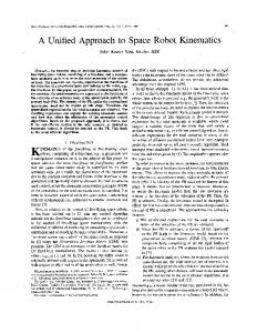
Am. J. Applied Sci., 7 (5): 669-674, 2010 The circles in the diagram represent the ends of the cross-members where the directional friction elements are added. Much like the scale this addition at the underside of the designated end of these members will result in low friction in the forward motion and high friction in other directions. One way this could be achieved would be fixing a sharp nail-like object with its pointed end sticking out at an angle. If it is attached at an incline with the pointed end heading backwards, this end could move forward without generating the “digging in” effect, while in the backward direction this effect would be great. In the lateral directions too, though not as great as in backward, the pointed object would tend to restrain movement. Another important factor is that these nail-like protrusions are added only to alternating links. In the above illustration this is indicated by the difference in shade: black representing the links with frictional elements and gray without.
rectilinear and the concertina, since sidewinding also requires the body to undergo a curve of even greater amplitude. The movement of lateral undulation and rectilinear motion are completely different and it would be unwise to try and implement both sets of movement in one robot. The concertina too has issues when considered in practical terms. Sinus-lifting is used in this type of motion, which means the robot must lift part of its body above the ground. To bypass this vertical degree of freedom, perhaps mechanisms could be added where friction could be controlled. Though it may be possible to design such a structure, it would hamper the ability of the robot to undertake lateral undulation. A robot developed exclusively for concertina motion would end up being highly inefficient in environs where space is not an issue. To overcome this conflict between the mechanics of concertina and lateral undulation, a completely different type of locomotion is introduced here considering the directional friction element of the snake scales on the underside of the body. The scales are arranged in a manner such that friction is low in the forward direction while high in reverse and lateral directions. Using this idea and adding additional elements to the generic design of the serpentine robot, a strategy for a novel type of locomotion is proposed. The strategy is evaluated through kinematic studies and its viability is supported through a prototype (Watanabe, 2008).
The inverse kinematics: In ascertaining the inverse kinematics, the first three links are considered as in Fig. 2. Let point A(a, b) denote the position of the bottom end of the cross-member of the first link, D(d, e) the position of the counterpart of Link 3, and H(h, k) the position of the joint between Link 1 and 2. If actuated in the correct direction, both the frictional elements at A(a, b) and D(d, e) will dig into the ground and the respective links will experience a moment about those points, hence rotating with those points as the centers. The horizontal length of each member is 2l and the vertical width 2w. To simplify the derivation let us assume w = l. The dimension r therefore denotes the base of the isosceles triangle ABH with side w and l. Then φ denotes the angle between the horizontal x-axis and the line connecting points A (a, b) and H (h, k). Furthermore, another design strategy that evolves directly from the geometrical relationship found in Fig. 2 is that of attaching the frictional elements only to alternate links. As is apparent from the Fig. 2, Link 1 and Link 3 rotate in arcs about point A and H respectively. Link 2 on the other hand does not move in a defined arc about a fixed point, and hence must be free to move. To facilitate this unimpeded movement, no frictional appendages are added. Moving on with the kinematics, following the geometric relations in Fig. 2, the coordinates of H(h, k) would be:
MATERIALS AND METHODS Structure of the snake segment: A new structure of snake robot is proposed here. The proposed structure is based on links which have cross-members. Each link is designed in the shape of cross with its vertical member having the same dimensions as the horizontal member and intersecting at the midpoints of both. In Fig. 1 a five-link structure is exemplified.
( r cos ϕ + a, r sin ϕ + b )
(1)
The length of segment c connecting D(d, e) and H(h, k) would be given by the expression: Fig. 1: Top view of the five-link model with an enlarged side view of the frictional elements
c=
670
( h − d )2 + ( k − e )2
(2)
Am. J. Applied Sci., 7 (5): 669-674, 2010 Link 2, is therefore evaluated by adding the angles concentric to point H. It would be important to note that though this angle appears to simply be
π in the initial 4
configuration, as Link 1 rotates about A in the clockwise direction, as in Fig. 3, this angle would clearly change. Angle θ can then be evaluated by subtracting π from the following expression: Fig. 2: Geometric relationship of the links for solving inverse kinematics
π⎞ π ⎛ ρ + ξ + ⎜ϕ − ⎟ + 2⎠ 4 ⎝
(8)
Thus angle θ can be expressed as: π⎞ π ⎛ ρ + ξ + ⎜ϕ − ⎟ + − π = θ 2⎠ 4 ⎝
(9)
Which when rearranged would give the final equation: θ=ϕ+ρ+ξ−
Fig. 3: Exaggerated view of the joint H for determining angle θ
(3)
⎛ 4l2 + r 2 − c 2 ⎞ γ = cos −1 ⎜ ⎟ ⎜ ⎟ 4lr ⎝ ⎠
(4)
⎛ r 2 + c 2 − 4l2 ⎞ λ = cos −1 ⎜ ⎟ ⎜ ⎟ 2rc ⎝ ⎠
(5)
ϕ2 = λ + ψ +
(6)
⎛ k−e⎞ ψ = tan −1 ⎜ ⎟ ⎝h−d⎠
(7)
π 2
(11)
The angles for following links can then be calculated using the same method on φ2 as was illustrated here with φ. Thus from the first angle φ, all other positions and angles between links can be determined. However, this still constitutes as inverse kinematics, since the angle that is actuated in the model is θ, and the resulting configuration and position of the structure is denoted by φ. Thus to anticipate the position of the members from the actuated angle θ, a forward kinematics needs to be developed. However, though the forward kinematics is not readily apparent, the maximum angle for θ is evident. As mentioned earlier, for the links to avoid singular positions and keep moving forward, at maximum deflection, the segment r of Link 1 must be in line with, i.e. parallel to, the lengthwise member 2l of Link 2. Keeping this in mind, it becomes clear that the range is:
Drawing a right triangle with its hypotenuse as segment c, two more angles are obtained: ⎛h−d⎞ ξ = tan −1 ⎜ ⎟ ⎝ k −e⎠
(10)
Similarly, referring back to Fig. 2, φ2, the Link 3 equivalent to the angle φ for Link 1, is:
Using the cosine rule on the triangle formed between the points D(d, e), H(h, k), and the joint between Link 2 and 3, the three angles ρ, γ, and λ can be determined as: ⎛ 4l2 + c 2 − r 2 ⎞ ρ = cos −1 ⎜ ⎟ ⎜ ⎟ 4lc ⎝ ⎠
5π 4
From all this, θ, the angle between the extension of the lengthwise axis of Link 1 and the central member of
−
671
π π ≤θ≤ 4 4
(12)
Am. J. Applied Sci., 7 (5): 669-674, 2010
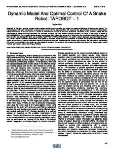
Fig. 4: Estimating forward kinematics from the ϕ Vs θ curve The forward kinematics: As is apparent from the above the variable ϕ is embedded deep into the equation. It appears in three separate places each time within an inverse trigonometric expression. To arrive at an expression with ϕ as a function of θ requires one to solve six quadratic equations simultaneously using a method involving resultants of polynomials. However, when the two variables are plotted on a graph as shown in Fig. 4 maintaining the range stated in (12), the curve does not appear too problematic. Thus, using regression techniques, a six-order polynomial equation is developed to estimate the relationship between the two variables. The forward kinematics is thus estimated as: ϕ = 0.065θ6 + 0.0708θ5 + 0.0302θ4 + 0.0537θ3 + 0.059θ2 − 0.5613θ + 2.2924
Fig. 5: Novel gait executed actuating two joints only The joint between Link 2 and 3 is actuated in the opposite direction so as to neutralize the effect of the moment on Link 3 from Link 1. If the remaining joints are not actuated links 3, 4 and 5 remain in line and only move forward along the axis of the lengthwise members. The following gait presents a few drawbacks, however. The entire movement rests on the action of only two actuators. Perhaps for a five-link robot the load may be bearable, but as the number of links increases, two actuators would not be able to carry the load and move forward.
(13)
Over the range mentioned in (12), this approximation has a maximum error of 0.08% and an average error of 0.004%.
All joints in motion: For this gait to be viable, all actuators must contribute to the forward movement. The same type of movement as the above is implemented here but repeated with all links. As is apparent from the first two links in the simpler version, the first joint traverses the full range of motion, while the second joint does not. To achieve maximum forward displacement on each thrust it would be wise to actuate the joints through its full range. Thus, the robot does not begin with a linear configuration, but rather in an oblique zigzag formation where the joint angles begin at their maximum or minimum values as shown in Fig. 6.
RESULTS Implementing the novel gait with two joints: Given the kinematics, the control algorithm for the joint actuators may be developed to push the robot forward. In this first example only the first two joints are actuated to achieve motion. As displayed in Fig. 5, actuating the first joint creates a moment on the first link. This moment then translates into the ends of the cross-members and the side that tends to move backwards would “dig in” and thus the whole link would rotate about that point. In the diagram, the “dug in” ends are marked with arrows. 672
Am. J. Applied Sci., 7 (5): 669-674, 2010 REFERENCES Burdick, J.W., J. Radford and G.S. Chirikjian, 1993. A ‘sidewinding’ locomotion gait for hyper-redundant robots. Proceeding of the IEEE International Conference on Robotics and Automation, May 2-6, IEEE Xplore Press, Atlanta, GA., pp: 101-106. DOI: 10.1109/ROBOT.1993.291864 Chen, L., Y. Wang, S. Ma and B. Li, 2004. Studies on lateral rolling locomotion of a snake robot. Proceeding of the IEEE International Conference on Robotics and Automation, Apr. 226-May 1, Hilton New Orleans Riverside, New Orleans, LA., USA., pp: 5070-5074. DOI: 10.1109/ROBOT.2004.1302521 Chernousko, F.L., 2000. Snake-like motions of multibody systems over a rough plane. Proceeding of the 2nd International Conference on Control of Oscillations and Chaos, July 5-7, IEEE Xplore Press, St. Petersburg , Russia, pp: 321-326. Hirose, S. and A. Morishima, 1990. Design and control of a mobile robot with an articulated body. Int. J. Rob. Res., 9: 99-114. hppt://www.ijr.sagepub.com/cgi/content/abstract/9/ 2/99 Hirose, S. and M. Mori, 2004. Biologically inspired snake-like robots. Proceeding of the IEEE International Conference on Robotics and Biomimetics, Aug. 22-26, IEEE Xplore Press, Shenyang, pp: 1-7. Hirose, S. and Y. Umetani, 1976. Kinematic control of active cord mechanism with tactile sensors. Proceeding of the 2nd RoMAnSy Symposium, Warsaw, pp: 241-252. Hirose, S., P. Cave and C. Goulden, 1993. Biologically Inspired Robots: Snake-Like Locomotors and Manipulators. Oxford University Press, ISBN: 10: 0198562616, pp: 240. Liu, C.Y. and W.H. Liao, 2004. A snake robot using shape memory alloys. Proceeding of the IEEE International Conference on Robotics and Biomimetics, Aug. 22-26, IEEE Xplore Press, USA., pp: 601-605. http://sciencestage.com/d/4680159/a-snake-robotusing-shape-memory-alloys.html Ma, S. and N. Tadokoro, 2006. Analysis of creeping locomotion of a snake-like robot on a slope. Autonom. Robots, 20: 15-23. http://portal.acm.org/citation.cfm?id=1117922.111 7924 Saito, M., M. Fukaya and T. Iwasaki, 2002. Serpentine locomotion with robotic snakes. IEEE Control Syst. Mag., 22: 64-81.
Fig. 6: The novel gait with more than 3 links DISCUSSION For the movement of the above snake model minimum of three links are required in contrast to the large number of links required by the existing snake models. As such this model is suitable for reprogramming in the case of malfunction of few of the links. Further observation into the shape of the robot shown in Fig. 6 shows that in executing the above gait lateral displacements of the links are low, which seems to be an advantage over the existing models of snake robots. Such a feature will help this robot move through narrow spaces. Again, the correct direction of actuation on the joints would produce a moment allowing the nail-like protrusions to “dig in.” As this occurs, the links would rotate about their respective centers. However, the links will not rotate at the same speeds. Due to geometrical constraints, the latter links can only begin to turn after the earlier leading links have started to undergo rotation. The leading first link will be the quickest to start the rotating process and slow down as it reaches the end of its range, while the latter links will start off slow and speed up as it approaches its final position. CONCLUSION A new link structure of snake robot is proposed in this paper along with its mathematical model for the solution of forward and inverse kinematics considering friction effects of snake scales. It has been shown that kinematically desired snake locomotion can be achieved through the computed joint angles of minimum of two links. This new structure is able to keep the lateral displacement low unlike the snake model with serpenoid shape that require large lateral displacement during executing motion and. 673
Am. J. Applied Sci., 7 (5): 669-674, 2010 Watanabe, M., 2008. Design and control of a snake robot for narrow space application. Proceeding of the 3rd International Conference on Mechatronics, ICOM’ 08, Malaysia. http://www.iiu.edu.my/ICOM/2008/
Yamada, H. and S. Hirose, 2006. Development of practical 3-dimensional active cord mechanism: ACM-R4. J. Robot. Mechatron., 18: 305-311.
674