Invited Review
JTTEE5 13:337-360 DOI: 10.1361/10599630419670 1059-9630/$19.00 © ASM International
P. Fauchais, M. Fukumoto, A. Vardelle, and M. Vardelle (Received January 15, 2003; in revised form April 24, 2003) This paper summarizes our knowledge at the beginning of 2003 about splat formation. First, the analytical and numerical models related to the impact and flattening of single particles on smooth or rough substrates with different tilting are recalled. Then, the different diagnostic methods, including imaging, are briefly described. The last part of the paper is devoted to the results and their discussion. Studies are related to the effect of various parameters on particle flattening. They include the characteristics of particles prior to impact: normal impact velocity, temperature, molten state, oxidation state, etc.; the parameters related to the substrate: tilting angle, roughness, oxide layer composition, thickness and crystallinity, desorption of adsorbates and condensates, wetting properties between impacting particle and substrate, etc.; and, finally, the parameters related to the heat exchange between the flattening particle and the substrate. They depend on previous parameters and control the propagation of the solidification front within the flattening particle, eventually modifying its liquid flow. It is obvious from this review that, if our understanding of the involved phenomena has been drastically improved during the last years, many points have still to be clarified. This is of primary importance because all the coating properties are linked to the particle flattening, splat formation, and layering.
Keywords
splat formation, sprayed particles, particle flattening
1. Introduction Plasma spraying is a well-established means of forming thick coatings (∼300 µm) used, for instance, for their resistance to corrosion, oxidation, and wear; friction, electric, magnetic, and ionic conduction properties; thermal protection; coefficient of thermal expansion tailored to service conditions; and strength with free-standing spray-formed components.[1] They are used in many industrial applications: mechanics, aeronautics, aerospace, chemistry and oil, electronic, military, automotive, medical, marine, and mining, and their development has continuously increased over the last decade.[2-4] In general, a successful application of thermal-sprayed coatings to engineering usage depends strongly on the quality of the adhesion between the coating and the substrate or the previously deposited layers. In most cases, the adhesion/cohesion is of the mechanical type; surface pits and grooves of a rough surface are filled with the spreading molten material due to the impact pressure. Subsequent solidification leads to mechanical interlocking. However, interdiffusion and possibly chemical reactions across the substrate or previously deposited layers may occur if the heat transfer from the impinging molten particles cause a local melting of the layer underlying the flattened particle. The latter is also called a lamella or “splat.” To summarize, the adhesion/cohesion of coatings is strongly linked, as well as many other properties (thermal, electrical, mechanical, etc.), to the quality of contact between the piled-up P. Fauchais, A. Vardelle, and M. Vardelle, SPCTS, UMR 6638, Univ. of Limoges, 123 Av. A. Thomas, 87000 Limoges, France; and M. Fukumoto, Toyohashi, Univ. of Technology, Toyohashi, Japan. Contact e-mail:
[email protected].
Journal of Thermal Spray Technology
splats. At impact, depending on its diameter, morphology, temperature, velocity, and chemistry, each particle flattens and the high pressure inside it forces melted material to flow laterally and ductile material to deform. The kinetic energy of the particle is transformed into work of viscous deformation and surface energy.[1,5] The flattening is controlled by mechanical and thermal constraints. The former are linked to the underlying surface roughness and its relative inclination toward the particle trajectory. The latter induce material solidification that depends on splat thickness, thermal diffusivities of both sprayed material and underlying solid layer, and quality of contact between the latter and the flattening particle. The quality of contact at the interface is a function of the particle impact pressure and varies drastically and nonuniformly along the contact surface during impact. The contact quality is also dependent on droplet wetting on the substrate and desorption of the adsorbates and condensates at the surface of the underlying layer. In addition, the contact between the piled-up splats is controlled by the relief of the quenching stress induced by the thermal contraction of splats upon cooling. The stored elastic strain energy can be released by various mechanisms: microcracking, plastic yielding, creep, etc.[6,7] The phenomena taking place at impact have different reference times:[1,5] one to a few microseconds for splat flattening, 3-10 microseconds for splat solidification, one-tenth to a few milliseconds for layer or pass formation, a few seconds to a few hours, depending on part size, for next layer or pass formation. Moreover, most phenomena are cross-linked. Thus, even though the study of splat formation and layering initiated in the ’70s, there is room for enhancing knowledge in this field. This paper is devoted to the presentation of what is our actual knowledge in splat formation. In the following sections the models, measuring techniques, and main results related to splat formation are successively described. The latter emphasize the importance of thermal contact resistance, effects of the oxide layer
Volume 13(3) September 2004—337
Peer Reviewed
Knowledge Concerning Splat Formation: An Invited Review
Peer Reviewed
at the surface, surface material diffusivity and roughness, and, lastly, parameters controlling deposition and/or splashing of the liquid material at impact.
scales ranging between a few micrometers and a few millimeters, and even centimeters in certain cases. Thus, models generally deal with:
2. Models
•
The complete modeling of coating formation is complex due to time scales ranging from microseconds to seconds and length
•
molten droplet at impact with its rebound, deposition, or splashing, single particle flattening with the taking into account of solidification before the end of flattening and possible splashing,
Nomenclature Latin alphabet
a ai A/C b c cl cpi CR dp D ef EF h hc K Kf Kfc Lp Ma ph pt P r Ra Re ReN Rt Rth S SF Stei tc
tps Tm To
ratio of flattening velocity vf to droplet impact velocity vp thermal diffusivity (i = s for solid phase, i = l for liquid phase), m2/s adhesion/cohesion of a coating, MPa splat thickness, m sound velocity, m/s sound velocity within the liquid droplet, m/s specific heat at constant pressure (i = s for solid phase and i = l for liquid phase), J/kg ⭈ K cooling rate, K/s impacting droplet diameter, m diameter of a splat supposed to be cylindrical, m thermal effusivity; ef = ( · cp · ⌲)1/2 elongation factor; ratio of the long length to the short one of an elliptically shaped splat convective heat transfer coefficient, W/m2 ⭈ K convective heat transfer coefficient for a perfect wetting ( = 0), W/m2 ⭈ K Sommerfeld parameter at impact K = We1/2 Re1/4 flattening splashing parameter critical value of Kf latent heat of solidification, J/kg impact Mach number; Ma = vp/cl water hammer pressure; ph = l · cl · vp, Pa transition pressure, Pa splat perimeter, m radius, m roughness average, µm Reynolds number; Re = vp · dp · /µ. At impact v = vp, upon flattening v = vf Reynolds number of the particle related to the normal component of the impact velocity vN roughness: distance between the highest peak and the deepest undercut, µm thermal contact resistance, K ⭈ m2/W splat surface, m2 splat shape factor; SF = P/4 · · S Stephan number; Stel1 = cp (Tp − Tm)/Lp for the liquid phase, Stes = cps(Tm − To)/Lp for the solid phase time at which an expansion wave propagates into the high pressure region lowering the pressure tc = dp · vp/4c2l1 preheating time, s melting temperature, K mean coating temperature, K
338—Volume 13(3) September 2004
Tp Tps Ts Tt vf vN vp vs Vm We
droplet temperature, K preheating temperature, K substrate temperature, K transition temperature, K maximum flattening velocity, m/s velocity component normal to the substrate (vN = vp · cos ), m/s particle impact velocity, m/s solidification velocity, m/s heating rate, K/s Weber number; We = · v2 · d/; at impact, v = vp; upon flattening, v = vf Greek symbols
K µ µo l p
dimensionless radius = 2 · r/dp contact or wetting angle, degrees thermal conductivity, W/m ⭈ K surface tension, J/m2 particle viscosity, Pa · s particle viscosity at melting temperature Tm, Pa ⭈ s kinematic viscosity; = µ/, m2/s flattening parameter or degree; = D/dp liquid droplet density, kg/m3 droplet density, kg/m3 angle between the normal to the substrate and the impacting particle trajectory or spray angle, degrees Abbreviations
AFM cw CCD dc EDS FP-S HVOF IM OM PDPA PECVD PSZ PVD rf SEM SS TEM XRD
atomic force microscopy continuous wave charge coupled device direct current energy dispersive x-ray spectroscopy flattening particle-substrate high-velocity oxyfuel flame interferometric microscopy optical microscopy phase Doppler particle analyzer plasma enhanced chemical vapor deposition partially stabilized zirconia physical vapor deposition radio frequency scanning electron microscopy stainless steel transmission electron microscopy x-ray diffraction
Journal of Thermal Spray Technology
• •
single splat cooling with nucleation at hypercooling temperature, splat layering, and deposition process.
Splat formation depends strongly upon the impacting particle temperature and velocity. Other factors also include the influence of oxidation on wetting properties and composition complexity (uniform composition and morphology or composite material), which affects heat propagation within the particle. Such parameters are linked to the spray technique used: flame, highvelocity oxy-fuel (HVOF), radio frequency (rf), or direct current (dc) plasma spraying, etc.,[1] and particle size. As soon as the particle temperature Tp is close to, but below, the melting temperature, spreading requires a high impact velocity (depending on particle diameter). Over melting temperature, the viscosity µ of the liquid phase decreases rapidly when Tp increases according to µ = µo · exp(E/RTp) where E is an activation energy and µo the viscosity at the melting point. Therefore, the spreading requires much lower impact velocities. The oxidation depends on the transport phenomenon controlling it.[8,9] For particles with a temperature close to the melting temperature, oxidation is diffusion-controlled and occurs in a shell at the particle periphery. It is generally limited to a few oxide weight percent. On the contrary, for fully molten particles, it may be promoted by convection within the liquid droplet. This phenomenon is about one order of magnitude more than with diffusion. The latter occurs as soon as the velocity difference between the particle and the flame (HVOF) or the plasma jet (dc) is high enough to induce a particle Reynolds number higher than 20 and when the ratio of the kinematic viscosities of the plasma and molten particle is higher than 50.[9] In addition, the oxidation level is also a function of the oxygen entrained by the jet which (a) increases with the jet velocity,[10,11] (b) diminishes with a shrouding gas, and (c) is, according to some authors, faster with atomic oxygen than with molecular oxygen. Atomic oxygen is essentially observed in dc plasma jets11 flowing in air.
2.1 Analytical Models of Splat Formation Several review papers[5,12-15] present the different theories developed. 2.1.1 Droplet Impact Perpendicularly to a Smooth Substrate Without Solidification. In all these models, the splat solidification is assumed to start only when flattening is completed. Incompressible Models. Upon impact, the liquid droplet can rebound, deposit, or splash, at least partially. This splashing corresponds to the ejection of tiny droplets mostly in the impact direction. In the following it will be called “impact splashing.” These phenomena are related, at least for a water or an ethanol droplet,[15-18] to critical values of the Sommerfeld parameter K of the particle at impact defined as K = We1/2 · Re1/4
(Eq 1)
where We and Re are the Weber and Reynolds numbers, respectively. K < 3 corresponds to rebound. 3 < K < 58 results in deposition, and K > 58 induces splashing.
Journal of Thermal Spray Technology
Under plasma spraying conditions, the limit between deposition and splashing is not so precise, but the trend is the same.[18] Moreover, with alumina particles sprayed by a dc plasma jet, calculated values of K vary between 50 and 1800,[18] which means that impact splashing is more the rule than the exception. Allen19 has suggested that splashing may be the result of Rayleigh-Taylor instabilities that occur when a fluid accelerates into a less dense one. Diameter of the Resulting Splat. The first papers, as summarized in Ref 12, were devoted to investigate droplet flattening onto a smooth surface. Such models allowed the calculation of the flattening degree = D/dp, where D is the diameter of the splat, assumed to be cylindrical, and dp is the diameter of the impacting droplet. This parameter is expressed as a function of the particle Reynolds number Re that quantifies the viscous dissipation of the inertia forces. Relationships of the type = C · Re␣
(Eq 2)
were established. According to the different authors, C varies between 0.8 corresponding to the mean diameter of an extensively fingered splat and 1.2941 for disk-shaped splat, and ␣ is either 0.2 or 0.125 or 0.167 (for more details see Ref 13). These models were improved by taking into account the liquid material surface tension by introducing the Weber number. The latter expresses the conversion of kinetic energy into surface energy. In these theories, the Weber number appears as We−1. However, it can be neglected, at least at the beginning of flattening, when the impact velocity vp is high as in dc plasma spraying, supersonic rf plasma spraying, and HVOF spraying. In that case, Eq 2 holds. Some theories also introduce the contact angle between liquid and solid at equilibrium that has an appreciable effect at the end of the flattening process. Compressible Models. Dykhuizen[12] and Armster et al.[15] recall that, due to their complexity, these models have only been used to study the initial impact and no results on final splat sizes have been obtained. Such calculations have shown that the maximum impact pressure of a spherical droplet is larger than the classic water hammer pressure p · cl · vp, where cl is the sound velocity in the liquid phase, p the density of the impacting liquid, and vp the particle velocity at impact. According to the review of Armster et al.,[15] compressibility governs the very first moment after a drop hits a surface. On impact the velocity of the liquid is suddenly changed and the liquid is compressed by the wave propagating into the drop. The compressibility is characterized by the impact Mach number (vp/ cl). For example, according to Armster et al.[15] for a liquid metal drop (l ∼ 8000 kg/m3), cl = 3000 m/s impacting at 300 m/s, Ma = 0.1, but the impact hammer pressure is already p ∼ 7 × 10⁹ Pa ∼ 70 000 atm. This pressure starts to be released after a time tc ∼ dp ⭈ vp/[4(cl)2]. With the above example and a droplet radius of 20 µm tc ∼ 3 × 10⁻¹⁰ s, which is very short compared with the flattening time ∼10−6 s. At that time tc, the radius of the contact zone equals rc = dp · vp/(2cl) = dp · Ma/2. In the preceeding example rc = 2 µm. This value has to be compared with the 20 µm of the splat radius. 2.1.2 Droplet Impact Perpendicularly to a Smooth Substrate With Solidification As soon as solidification starts before flattening is completed, the flattening process is drastically modified.
Volume 13(3) September 2004—339
Peer Reviewed
•
Peer Reviewed
Cooling Rate. The cooling of the flattening droplet is mainly due to heat conduction to the substrate or the previously deposited layers. The cooling rate has been predicted using analytical or one-dimensional (1D) heat transfer models. It depends on the following effects.[19-23] First, cooling rate depends on the quality of the contact between the splat and the underlying material. A very simple model[14] gives the cooling velocity as Vs = hTp/(Lp)
(Eq 3)
where Lp is the latent heat of solidification, Tp the particle temperature, the density of material, and h the heat transfer coefficient at the interface. This expression shows that h has a drastic effect on the solidification rate at the interface. Solidification generally starts at the end of the flattening process;[5,12-15] i.e., when surface energy becomes important. If the contact is uniform, h can be expressed in terms of the wetting angle through h = 0.5 hc (1 + cos )
(Eq 4)
hc being the heat transfer coefficient for perfect wetting ( = 0). Instead of h, the thermal contact resistance Rth = 1/h is often used. Rth makes it possible to quantify the quality of contact between the splat and the underlying layer. A perfect contact corresponds to Rth ∼ 10−8 m2 K/W while a poor contact is about 10−6 m2 K/W. Secondly, during phase transition the latent heat of fusion is released. This provides a heat source that needs to be compared with other sources. The Stephan number is a measure of the solidification time. It is defined as the ratio of the sensible to the latent heat Stes = cps(Tm − Ts)/L where cps is the heat capacitance of the solid phase, L the latent heat of fusion, Tm the melting temperature, and Ts the temperature of the substrate. It is also sometimes defined for the liquid phase as Stel = cpl(Tp − Tm)/L where cpl is the heat capacitance of the liquid phase, and Tp the impacting droplet temperature. Third, the ratio of splat to substrate thermal diffusivities characterizes the cooling rate, especially for a perfect contact. Lastly, a great effect is linked to splat thickness. The cooling rate (CR) decreases drastically when the splat thickness increases. Therefore, CR will be much lower with subsonic rf plasma-deposited splats than with dc plasma-deposited splats. Also, CR should be higher at the periphery of the flattening droplet, provided that the contact is perfect. At the splat rim, where the contact pressure is very low and the surface tension is at a maximum, splat curling occurs and the contact of the flattening particle with the substrate is very poor, thereby inducing a slower liquid cooling through the already solidified part of the splat and a rounded rim due to the surface tension. Outside the rim area within the splat, the contact splat-substrate is good and splat thickness is lower. Therefore, in principle, solidification would start there. However, in this area the reduced radius = 2r/dp might be higher than 2 (Section 2.2.1). Then the contact pressure may not be sufficient to overcome the pressure resulting from flash evaporation of condensates or adsorbates at the surface and the disturbance of the spreading process by asperities and surface defects, resulting in a high local thermal contact resistance. Thus, solidification will start in an area where the flattening droplet is thinner but the impact pressure higher. Solidification Process. According to the high CRs achieved in plasma spraying (up to 109 K/s at the very beginning of the
340—Volume 13(3) September 2004
cooling process), the flattening droplet undergoes hypercooling, generally resulting in heterogeneous nucleation starting at contact with the underlying material.[22,24,25] The rate of nucleation and crystallization can be calculated from the classic theory of nucleation when assuming a steady-state process. The critical free-energy change required to reach the critical size of embryos is linked to the contact angle that affects the lowering of the activation energy required for nucleation. Reciprocally, the experimentally observed size of the columns within splats, allows the determination of the values of and cooling rates. Splashing During Flattening Process. At the end of the flattening process, the starting solidification, especially close to the splat periphery where it is thinner, may impede the liquid flow and splashing will occur.[26] However, it will proceed almost parallel to the substrate surface and result in extensively fingered splats. A similar phenomenon will occur when the liquid flow encounters surface asperities. 2.1.3 Droplet Impact Perpendicular to Rough Surfaces. Approximate equations describing the time evolution of the splat thickness and radius during the flattening process, and taking into account the surface roughness,[27] have been proposed in the literature. It is assumed that roughness increases the shear stress due to the friction between the flattening droplet and rough surface. A mathematical model including different geometrical asperities has been developed by Fukanuma[28] and recently improved.[29] The main problem is the estimation of the roughness relative to the splat thickness, and a fractal dimension indicator has been proposed.[30] These models show that the surface roughness promotes splashing at impact and during flattening. Splats are extensively distorted. As they are thicker (up to three times) than those obtained on smooth substrates, their cooling rate is decreased. 2.1.4 Off-Normal Impacts. Models of off-normal impacts have been developed for smooth surfaces. They generally neglect solidification that is assumed to start when flattening is completed.[15,31-35] Expressions of the elongation factor (EF; ratio of the long length to the short one of the splat assumed to be elliptical) have been established. This ratio is independent of the splat size and depends only on the spray angle .[32-34] Other theories relate the mean splat thickness to a Reynolds number, ReN in which the considered velocity is the normal component of vp (vN = vp · cos , where is the angle between the normal to the substrate and particle trajectory: vN = vp when the substrate is orthogonal to vp: = 0). As a matter of fact, the splat thickness varies along the longer axis of the ellipse and is thicker in the liquid material flow direction. Thus, the onset of solidification occurs most likely in the thinner part of the splat. It will promote horizontal splashing in the liquid flow direction, especially when increases. Experimentally, it has been shown that the effect of the spray angle on coating properties is weak as long as > 45°. Above that value, coating porosity and roughness increase while mechanical properties decrease.[33,36] 2.1.5 Impact Pressure. As summarized by Dykhuizen,[12] Sobolev et al.,[14] and Armster et al.[15] (Section 2.1.1), the impact pressure determined by compressibility effects can be very high. It generates a pressure pulse distributed along a radius rm generally smaller than the final splat radius. The contact pressure spreads out and dissipates quickly with droplet flattening. For a given impact Reynolds number, the pressure at the end of
Journal of Thermal Spray Technology
Peer Reviewed
the flattening process increases with the surface roughness and decreases with an increase in the solidification velocity. According to these results, the splat adhesion will be the best in its central part. In the periphery, the impact pressure will not necessarily overcome the capillary pressure due to roughness and gas pressure. The latter results from the fast evaporation of adsorbates and condensates at the substrate surface or trapped between splat and substrate. This results in poor contact.
2.2 Numerical Simulations of Droplet Impact Various numerical studies have dealt with the impact of a thermal-sprayed particle on a smooth surface and, recently, on rough surface with the layering of splats. 2.2.1 Impact of a Droplet Perpendicular to a Smooth Substrate. Different studies[37-42] assume a two-dimensional geometry and a perfect contact between splat and substrate (Rth = 10−8 m2 K/W). Moreover, the simultaneous heat interaction of the droplet with the substrate is not taken into account. The most advanced models solve the flow equations by considering convective, viscous, and surface tension processes. They allow the prediction of the effect of particle parameters on splat formation. The projected trends agree well with the analytical models. However, they cannot predict the breakup or splashing of the flattening particle onto the surface. In addition, these models enable the calculation of the contact pressure time-evolution for different flattening particle radii.[43,44] The predictions of analytical models are also confirmed. The low contact pressure at the interface for a reduced radius = 2r/dp > 2 is not necessarily sufficient to overcome the gas and capillary pressures resulting in a poor contact, especially at the splat periphery. 2.2.2 Impact of Droplets Perpendicular to a Substrate Already Covered With Deposited Splats. The most sophisticated models involving three-dimensional flow, cooling of the flattening particle with a thermal contact resistance at the splatsubstrate interface, flattening splashing based on the RayleighTaylor instability theory, and impact of a molten droplet on a previously deposited splat, have been developed by Mostaghimi and his co-workers.[26,45-51] Such calculations show the drastic influence of the beginning of solidification relative to the droplet flattening stage on the flattening splashing phenomenon as well as the effect of the substrate roughness, represented by the already deposited splats. The solidification process is controlled by the thermal contact resistance. According to the assumptions of Pasandideh-Fard et al.,[26] splashing is mainly observed when the thermal contact resistance Rth is close to zero. A slower solidification rate, when Rth is on the order of 10−6 m2 K/W, results in much less breaking or flattening splashing. However, these results, as it will be seen in Section 4.2.3., are at variance with experiments.
2.3 Deposition Process The models of coating formation generally use simple analytical correlations to predict the final size of the splat after impact and a set of physically based rules for combining the impact events to make the deposit (see the review in Ref 5). The results depend strongly on the rules and assumptions used. Moreover, phenomena such as cracking in ceramics, creeping, plastic yield-
Journal of Thermal Spray Technology
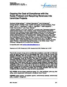
Fig. 1 Collection of particles at a given location using a 10 mm hole in a fixed steel plate and moving graphite shutter with a 32 mm hole; the mean velocity and temperature of the impacting particles are followed by a DPV 2000[56]
ing, interfacial sliding in metals, and impact angle favoring shadow effect and splashing are neglected. A simple 1D thermal model related to splat layering[52] makes it possible to calculate the temperature history during coating formation and relate it to stress development.
3. Diagnostics 3.1 Observation of Isolated Splats 3.1.1 General Remarks. The simplest way to obtain information about splat formation is to observe splats on a substrate using optical microscopy (OM), interferometric microscopy (IM), scanning electron microscopy (SEM), atomic force microscopy (AFM), surface profilometry, and transmission electron microscopy (TEM). The observation of splats requires that they be separated from each other. This imposes a powder feed rate below 50-100 g/h to limit the number of collected particles. To obtain an outlook of the sprayed spot, the method proposed by Roberts and Clyne[53] and improved by Bianchi et al.[54] can be used. It consists in moving the torch and the substrate in two opposite directions with a slot in between them. Thus, the deposition spot, which in dc spraying represents an ellipse with a long axis of about 20 mm, can be enlarged, at least along one direction, up to 80120 mm. This allows the collection of a few thousand splats resulting from particles that have traveled in different zones of the plasma jet and, therefore, exhibit different velocities, temperatures, and diameters at impact. If one does not care about the radial position of the collection, a glass plate traversing the jet rapidly (for example, fixed on a pendulum) is a good solution. If the collection position is important, a hole in a plate, a few millimeters in internal diameter and positioned relative to the torch axis, can be a good solution provided it is protected by a water-cooled or a graphite shield which intercepts plasma jet and particles. The shield is opened for less than 1 s to collect a few particles.[55] A modified particle-collecting apparatus was proposed by
Volume 13(3) September 2004—341
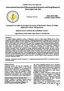
Peer Reviewed Fig. 2 (a) Observation by optical microscopy of zirconia splats collected on a smooth Ra < 0.05 µm hot (Ts ∼ 300 °C) stainless steel substrate; (b) shape factor distribution of 5000 splats from image analysis[54]
Fukumoto[56]; it is shown schematically in Fig. 1. This device is made up of a fixed steel plate with a 10 mm hole and a moving graphite shutter with a 32 mm hole. It is placed between the plasma torch and substrate and enables the collection of particles with rather homogeneous properties. The number of particles deposited on the substrate in one pass of the shutter is around 50. Almost no increase in the substrate temperature is detected when using this collection method. The observation of splats allows the investigation of the role of the substrate material; i.e., its specific preparation (chemistry, roughness, desorption of adsorbates, and condensates), temperature, oxidation stage, and oxide layer composition. More information is obtained if the parameters of particles during the impact and flattening processes are determined, as described in Section 3.2. 3.1.2 Information Determined by the Various Techniques. OM allows the observation of many splats (1005000) on a smooth surface (Ra < 0.2 µm) and the determination of their shape factor (Fig. 2) and flattening degree by image analysis. The shape factor SF is defined by the dimensionless parameter: SF = (4S)/P2
(Eq 5)
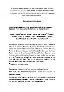
where P is the perimeter of the splat and S its surface. For a disk-shaped splat, SF = 1 and SF decreases when the splat is jagged. Sometimes the shape factor is defined as 1/SF and in that case, an extensively fingered splat has a shape factor higher than 1. Surface profilometry enables the measurement of the splat geometry and, also, an estimation of adhesion if the splat is pulled off by the profilometer tip.[57] IM is a non-contact surface profilometer (a scanning whitelight interferometer) and can be used for sizes over 0.1-1 µm. AFM is mainly used as a profilometer with a contact tip a few atoms wide, allowing the observation of details in the 0.1 µm size or less, such as the columnar structure of the splat or details of a crack or rim[55] (Fig. 3). SEM allows the observation of details that are not observable
342—Volume 13(3) September 2004
Fig. 3 Observation by AFM of the columnar structure within a small area (5 × 5 µm2) of a splat presented in Fig. 2[55]
by OM or IM and the study of splats on rough surfaces (Rt ∼ 100 µm). However, the samples need a specific preparation, especially ceramic ones. TEM requires careful preparation, for example, by a modified wedge polishing technique to bring the sample near electron transparency followed by ion milling. It allows the study of the interface between the splat and substrate as well as of the local chemistry by energy dispersive x-ray spectroscopy (EDS)[58] (Fig. 4).
Journal of Thermal Spray Technology
It is important to underline that the columnar or equiaxed structure of the splats, size of the columns or grains, and regularity will provide information on the splat-cooling rate. The orientation of the columns will indicate the direction along which the heat was withdrawn. For ceramic materials, the spacing between the cracks resulting from the quenching stress[1] will also indicate the cooling rate.
3.2 Observations of Sprayed Droplets at Impact Experimental data on droplet impact under thermal spray conditions are scarce, due to the difficulty of obtaining accurate information on micrometer-sized particles impacting at velocities in the hundreds of meter per second range. Thus, experiments have been developed with millimeter-sized particles impacting at a few meters per second but with about the same Reynolds and Peclet numbers as those of thermal sprayed particles. However, the importance of the phenomena involved, such as the degree of undercooling, nucleation delay, and con-
Journal of Thermal Spray Technology
Volume 13(3) September 2004—343
Peer Reviewed
Fig. 4 Observation by TEM[58] of the interface between a zirconia splat and a stainless steel substrate (smooth Ra ∼ 0.05 µm and preheated at 450 °C): (a) 30 nm scale, (b) 500 nm scale. The bright interface layer is overexposed due to its lower thickness.
tact resistance, is not the same in systems differing by two or three orders of magnitude for the particle impact velocity and diameter.[12] Five typical experiments are briefly presented as follows in this section. 3.2.1 Experimental Arrangements for the Study of Particle Impact and Flattening Under Thermal Spray Conditions. The aim of these arrangements is to estimate the flattening time, evolution of the flattening degree (ratio of the splat diameter if disk shaped, or equivalent diameter if fingered, to the original particle diameter) and cooling rate evolution both of the impinging particle and resulting splat. Of course, such information can be completed by the observation of the resulting splat using the techniques described in Section 3.1. An initial experimental setup proposed by Moreau et al. uses a fast pyrometer (∼100 ns in response time) focused onto the substrate to measure the parameters of a single particle prior to its impact and determine its temperature evolution during the flattening and cooling stages.[59-63] The light emitted by the particle is focused onto the tip of an optical fiber covered with an optical mask opaque to near-infrared radiation except for three slits. Figure 5 shows the experimental setup and the principle of measurement. On a glass substrate, the splat-diameter evolution during its cooling can also be measured, independently of thermal radiation, by using the attenuation of a laserdiode beam.[63] A second setup developed by Vardelle et al. consists of a pyrometer focused onto the substrate and a phase Doppler particle analyzer (PDPA).[64,65] The latter allows the measurement of the velocity and size of the particle independently of its temperature, while particle temperature before and during impact is measured by a fast (50 ns) two-wavelength pyrometer (Fig. 6). 3.2.2 Imaging of Droplet Impact Mode: Rebound, Deposition, and Vertical Splashing. To observe these phenomena, it is necessary to use an imaging device that allows the visualization of particles with known velocity, temperature, and diameter when they impact on substrates of which the temperature, roughness, and tilting angle are monitored. The impact of a single particle is observed in a controlled-atmosphere chamber (Fig. 7).[18,66,67] The particle parameters prior to impact are measured by two-color pyrometry and phase Doppler particle analyzer (Section 3.2.1). The particle image during impact, splashing, deposition, or rebounding is obtained by a fast camera (exposure/delay time 100 ns to 1 ms) with possible multiexposures. The camera is triggered by the PDPA and/or pyrometer. As the exposure time is short (down to 100 ns) and the image of the particle is focused on the camera lens with the help of a long distance microscope; the hot particles have to be illuminated by a 2-W continuous wave (cw) laser beam. The camera axis is parallel to the substrate, or more precisely, to its axis when it is inclined. Thus, the camera can visualize the phenomena occurring in the direction orthogonal to the substrate and not those parallel to it. 3.2.3 Measurements of Millimeter-Sized Particles at Impact. Figure 8 shows the setup developed by Fukumoto et al.[56,68-71] and used in a controlled-atmosphere chamber where soft vacuum (1 kPa) or atmospheric pressure (105-107 kPa) can be maintained. The millimeter-sized particles are produced by melting a 2 mm diameter wire of metal with rf equipment. Substrates are heated by a resistor and kept at a given temperature
Peer Reviewed Fig. 5 (a) Schema of the thermal-spraying experimental set-up using one pyrometer for the study of particle impact,[61] (b) schema of the pyrometer field of view. The particle is seen through the three slits of the optical mask and moves toward the substrate.[61] (c) Schematic signal of the particle thermal emission collected through the three-slit mask as shown in (b).
measured by a K-type thermocouple. To examine the effect of substrate wettability with almost no change in thermal diffusivity, they are coated with thin physical vapor deposited (PVD) films (a few tenths of micrometer) of different materials such as gold. A high-speed camera allows the observation of the droplet impact behavior, especially flattening, splashing, and diameter evolution during flattening. A similar setup has also been recently developed by Mehdizadeh et al.[72]
4. Results and Discussions 4.1 General Remarks Flattening and solidification of individual particles thermal sprayed onto a substrate and subsequent layering control the coating formation and its thermomechanical and service properties. The phenomena involved are very complex and depend on many parameters. The impacting particle parameters include temperature and
344—Volume 13(3) September 2004
Fig. 6 (a) Schema of the experimental set-up using a pyrometer and a phase Doppler particle analyzer (PDPA) for the study of particle impact,[65] (b) schematic signal of the particle thermal emission before and after impact[65]
its distribution within the particle, velocity, diameter, oxidation at the particle surface with a liquid or solid oxide layer, oxidation within the particle due to convection, and uniformity (or nonuniformity) of particle composition for composite material. The substrate parameters include surface temperature, roughness relative to particle size, tilting toward the impacting particle direction, oxidation state with respect to composition, thickness and roughness of the oxide layer, and presence of condensates and/or adsorbates at the substrate surface or presence of organic products. In the following, the roughness is characterized by the Ra. However, as briefly discussed in the Appendix, very different-looking topographies can exhibit the same Ra measurement. Thus other definitions of roughness should probably be used, such as fractal. Also, some phenomena at impact are related to both types of parameters: for example, (a) at the early stage of the impact; rebound, deposition, or partial impact splashing are important and (b) at the intermediate stage of the impact when the Weber
Journal of Thermal Spray Technology
Peer Reviewed
Fig. 7
Schema of experimental setup to visualize the impact of particles with known parameters (temperature, velocity, diameter)[67]
number is still high (We > 100), particle flattening involving mainly the molten liquid flow. At the end of flattening, two phenomena become critical. On the one hand, particle solidification is important and it depends, to a great extent, on the thermal contact resistance Rt between the flattening particle and substrate (FP-S) or the previously deposited layers. However Rt, which is often used in models, is an integrated value representing the FP-S true contact. When Rt is small (∼10−8 m2 K/W), it can be assumed that more than 50-60% of the final splat surface, mainly its central part, is in contact with the substrate or the underlying layer. When Rt increases, the surface area percentage corresponding to a good FP-S contact is drastically reduced and can be unevenly distributed. In the area of good contact, the underlying surface heating is good, the cooling rate is high, and the grain or column sizes in the splat are small, in the range of a few hundreds of nanometers. However, as the flattening process cannot be completed when the solidification starts in the thinnest area, the liquid flow can be impeded and splashing occurs. This type of splashing is called “flattening splashing.” Similarly, any asperity of the surface will impede the flow of the liquid material and promote splashing. It is also important to underline that the quality of the FP-S contact depends strongly on the vaporization of condensates, adsorbates, and organic products present at the surface. A very good contact can also result in the melting of a thin layer of the substrate or oxide layer at the substrate surface and thus promote the adhesion by a
Journal of Thermal Spray Technology
Fig. 8 Schematic drawing of the experimental setup to study the impact of a millimeter-sized particle[71]
Volume 13(3) September 2004—345
Peer Reviewed
Fig. 10 Variation of the adhesive strength of the coating with substrate temperature[74] (Ni sprayed material with a size distribution 10-44 µm; stainless steel AISI304 substrate) Fig. 9 Splashing at impact of alumina droplets impacting on a hot stainless steel substrate preheated at 600 K with (a) K = 139, (b) K = 229, (c) 776, and (d) 1346[18]
chemical reaction between the molten layer and the flattening particle (Section 4.3.1). On the other hand, the particle surface tension and wettability can dramatically modify the liquid flow.
4.2 Droplets Impacting Perpendicular Onto a Smooth Substrate 4.2.1 Rebound, Deposition, and Splashing at Impact. As emphasized in Section 2.1.1, for a droplet that does not undergo solidification, the Sommerfeld parameter K characterizes the phenomena at impact. With the setup described in Section 3.2.2, Escure et al.[18,66,67] have investigated the deposition and splashing conditions for K values ranging between 4 and 1800. The deposited particles were alumina and the substrates, either stainless steel or alumina. The temperature of the stainless substrate was varied between 600 and 1100 K and that of alumina substrate between 600 and 2300 K. At 600 K, stainless steel and alumina substrates are over the transition temperature, as defined in Section 4.2.2, and corresponding to splats that exhibit no flattening splashing (disk-shaped splats). On alumina substrate at 2300 K, no solidification can occur before flattening is completed. Typical results are shown in Fig. 9 for K values between 139 and 1346. It can be seen that the quantity of splashed droplets (in the 1 µm range) increases with K. For impacting particles with a mean diameter of ∼30 µm, splashed droplets reach heights of about 3 mm. The size of the splashed droplets is in the micrometer range and corresponds to a rather small quantity of the impacting material. Moreover, these small particles reach a distance high enough from the substrate to be outside the dynamic boundary layer and, thus, entrained by the plasma flow. Contrary to what has been observed with ethanol droplets,[16] the transition between deposition and splashing is not exactly at
346—Volume 13(3) September 2004
K = 57.7. Whatever may be the substrate temperature, deposition occurs for K between 4 and 70 while splashing is observed down to K = 10 and is the rule for K > 70. This dispersion might be due to (a) the fact that the smooth surface becomes rough after the impact of 5-10 particles and (b) the measurement accuracy of K on the order of 30%. 4.2.2 Transition Temperature. When spraying different materials on smooth (Ra < 0.5 µm) substrates made of different materials, the following phenomena are observed. Below a substrate temperature, linked to substrate and impacting droplet materials, splats are extensively fingered while above this temperature, they are almost disk shaped. The splat fingers corresponding to splashing parallel to the substrate surface, are termed as flattening splashing. The latter differs from the “impact splashing” defined in Section 4.2.1. The most interesting feature lies in the drastic change from fingered-splat pattern to the almost disk-shaped one at a certain narrow temperature range when the substrate temperature increases. The transition temperature Tt at which the splat shape changes was defined and introduced by Fukumoto et al.[56] The fact that the splat pattern varies with the substrate temperature has been recognized by many investigators such as, for example, Houben.[73] However, this transition temperature has not been well understood until the recent years where the change in the splat pattern near the transition temperature has become a great concern. Many authors have shown that, when disk-shaped splats were obtained on a smooth substrate (Ra ∼ 0.05 µm) preheated at temperature Ts higher than the transition temperature Tt, the adhesion of coatings of the same material sprayed on the same rough substrate also preheated at Ts was 2-5 times higher than that sprayed on a substrate preheated at Ts < Tt.[74-77] Figure 10 shows the effect of substrate temperature on the coating adhesion. The adhesion strength changes progressively with substrate temperature. Its dependence on substrate temperature corresponds quite well to that of the splat shape on a smooth substrate. Thus, investigation of the flattening mechanism of the sprayed particles is significantly meaningful for the practical use of thermal spray coatings.
Journal of Thermal Spray Technology
Peer Reviewed
Fig. 11 Relationship between the thermal conductivity of substrate and the transition temperature[83]
The observation of bottom surfaces of splats shows that, generally, they exhibit numerous pores and rapidly solidified structures at low substrate temperature. It seems that splat solidification starts at points unevenly distributed at the bottom of the flattening particle and the resultant solidified part affects drastically the flowing behavior of the molten part. Almost no pores can be observed with a solidification structure looking quite flat and dense over more than 50-60% of the bottom surface of splats, at substrate temperatures higher than Tt. In the latter case, solidification occurs most likely when flattening is almost completed. Similar observations of rapidly solidified microstructures in the bottom part of splats have been made by Safai[78] and Sampath.[79] Inada and Yang[80] suggested that the rapidly solidified layer at the bottom surface affects the flow behavior of the upper molten part. The most recent numerical simulations by Mostaghimi support this hypothesis.[81] It is inferred that the rapidly solidified layer formed just after the impingement on the substrate plays an important role for the flattening process. Preheating a metallic substrate over the transition temperature Tt may result in the formation of an oxide layer at the substrate surface. The latter results in the formation of jagged splats and, correlatively, a decrease in coating adhesion.[54] The most probable explanations concerning the transition temperature deal with the desorption of adsorbates and condensates at the substrate surface, wetting of the substrate by the liquid material, and solidification effects.[68-87] The flattening behavior and the grain or column size of the resulting splat have been observed systematically for many particle/substrate material combinations (for example, Ref 68, 83, 88-90). Influence of Intrinsic Properties of Substrate and Particles With No Substrate Melting. The flattening and solidification behavior of nickel (Ni) particles (in the millimeter-size range) were observed on different substrates when the wetting at the particle/substrate interface was kept constant. It was achieved by depositing a thin coating ( Tt) or at 348 K (Ts < Tt) with (a) particle velocity and (b) particle temperature[106]
formed at the University of Limoges in France[23,54,55,64,65,75,101-107] for zirconia particles, and at IMI, Boucherville, Canada[60-63] for Mo particles. For example, for zirconia particles (22 and 45 µm), impacting on polished (Ra < 0.05 µm) 304L stainless steel substrate, the cooling rates were between 4 and 10 times higher when the substrate was preheated at 573 K compared with 348 K below the transition temperature as shown in Fig. 19. The diskshaped splats obtained when Ts > Tt exhibited excellent contact with the substrate (more than 80% of this surface) except in the splat rim (Fig. 2a). The corresponding columnar structure exhibited regular column sizes in the 100 nm range. On the contrary, splats collected on substrates with Ts < Tt presented only a small contact area in the 10-20% range, with much bigger grain sizes in the area of poor contact.[54] Similar results, at least for the size of the columnar structure, were obtained recently[58] for zirconia splats. The cooling rates of zirconia droplets were also studied when spraying on a partially stabilized zirconia substrate, the roughness of which was slightly higher than that of a stainless steel substrate (Ra = 0.2 µm against 0.05). The cooling rate, for a particle impacting with about the same velocity, temperature, and diameter on stainless steel and zirconia substrates preheated at 600 K (that is, over Tt for both substrates) was 113 K/µs on the partially stabilized zirconia (PSZ) substrate instead of 643 K/µs for the stainless steel substrate. In both cases, splats exhibited perfect disk shapes. When performing the calculation of the cooling rate of a splat on both substrates, assuming a perfect thermal contact resistance (Rt = 10−8 m2 K/W), the difference in cooling rates was explained by the thermal diffusivity values, a,
Journal of Thermal Spray Technology
Kf = Wef0.5Ref0.25 = (bvf2/) 0.5(bvf /µ)0.25 = 0.75b0.75vf1.25/0.5µ0.25
(Eq 6)
The maximum flattening velocity vf changes with substrate temperature. Its relationship with the impact velocity vp can be expressed as vf = a · vp
(Eq 7)
where a is the ratio of the maximum flattening velocity to the impact velocity of particle that takes into account the effect of the substrate temperature change. Therefore, a is a function of both substrate temperature and impact velocity: a = f (Ts, vp). Furthermore, it is assumed that the splat thickness b is constant during the flattening process and is equivalent to that obtained when the flattening is completed. The particle deforms from a spherical to a cylindrical shape just after the impact and the splat
Journal of Thermal Spray Technology
thickness b can be calculated from the conservation equation of mass: b = 2dp3/3D2
(Eq 8)
where D is the splat diameter. It is then assumed that the equation of Madejski for the flattening ratio[107] can be used D/dp = 1.29 × Re0.2
(Eq 9)
By substituting Eq 9 into Eq 8, the expression of b is given by b = 0.4 × dp × Re−0.4
(Eq 10)
and by substituting Eq 10 into Eq 6, the new criterion Kf, based on the flattening parameter, is given as Kf = 0.75b0.75vf1.25/0.5µ0.25 = r0.75(0.4 × dp × Re−0.4)0.75 (a × vp)1.25/0.5 µ0.25 = 0.5a1.25Re−0.3( × dp × vp2/)0.5( × dp × vp/µ)0.25 = 0.5 × a1.25Re−0.3K
(Eq 11)
K being the Sommerfeld parameter at impact (Eq 1 in Section 2.1.1). To evaluate Kf and the splat morphology, a concrete value of a is required. However, the flattening velocity of the thermal spray particle cannot be measured because the flattening is too fast (about 1 µs in dc spraying). Therefore, a value was measured by the free-falling droplet experiment under Reynolds and Peclet numbers equivalent to those experienced in thermal spraying. The experimental results are shown in Fig. 20(a) for Ni droplets impacting on a stainless steel substrate. It is found that a decreases monotonically with increasing Ts. Also, a remarkable change in a value occurs transitionally at the substrate temperature of Tt. This change corresponds to the change in the splat shape from splashed splat to disk-shaped splat. That is, once the disk-shaped splat is formed, the flattening velocity suddenly decreases. Thus, the flattening splashing is due to the rapid flow of the liquid during flattening. For thermal spray particles, it is expected that a similar change of a near Tt occurs. Figure 20(b) shows the calculated results of Kf. As Ts increases, Kf decreases gradually with a discontinuity for a substrate temperature of Tt. When Ts = Tt, the critical value of Kf is calculated as about 7. This corresponds to Kfc that is the criterion for the flattening splashing. On the one hand, if Kf of the splat is smaller than Kfc(=7), a disk-shaped splat is formed; on the other hand, if it is larger than 7, flattening splashing will occur. 4.2.5 Other Parameters Affecting Particle Impact. Besides the previously cited parameters, other parameters may also affect the transition between a fingered splat and a perfect diskshaped one as well as splat adhesion. Crystalline Structure of the Substrate. Alumina particles were sprayed onto polished (Ra ∼ 0.4 µm) plasma sprayed coatings.[108] The latter were either as-sprayed (with more than 99 wt.% of ␥ phase) or preheated at 1373 K at a rate of 5 K/min, annealed for 6 h and cooled at a rate of 5 K/min resulting in a 100% ␣-columnar structure. Some were also preheated to 1873
Volume 13(3) September 2004—351
Peer Reviewed
of both substrates (aPSZ = 0.7 × 10⁻⁶ m2 s−1 against aSS = 5.2 × 10⁻⁶ m2 s−1).[23] Similar calculations of the splat cooling on a stainless steel substrate preheated over Tt showed that all disk-shaped splats corresponded to Rt ∼ 10−8 m2 K/W, while all fingered splats (Ts < Tt) corresponded to Rt ∼ 10−6 m2 K/W. Such results are in contradiction with the calculations performed by the team of Mostaghimi.[26,49,50] In their last paper,[26] where they have studied both numerically and experimentally the impact of Ni particles on stainless steel, they found, from modeling, that splashing occurred if Rt = 10−8 m2 K/W while disk-shaped splats were obtained for Rt = 10−6 m2 K/W. In the latter case, solidification only occurs when flattening is completed. However, they recognized[100] that when spraying alumina on stainless steel, splashing that occurs for Ts < Tt is not predicted by their model. Such measurements support the conclusion made in the previous Section (4.2.2) about the role of the wetting and desorption of adsorbates and contaminants on the flattening and cooling of the impacting droplet. 4.2.4 Modified Sommerfeld Parameter for Flattening Splashing. The impact splashing is characterized by a Sommerfeld parameter K higher than 58 even if splashing can occur for lower K values (Section 4.2.1). The flattening splashing is not at all linked to the particle impact velocity because when varying it between 30 and 300 m/s for the same material and substrate,[54,75] splats are disk shaped as soon as substrate temperature is over the transition temperature Tt. Thus the flattening splashing occurring for Ts < Tt when flattening is almost completed is linked to the flattening velocity vf of the liquid flow. This velocity vf depends on the initial particle impact velocity vp but also on the liquid thickness controlling the splat cooling rate (with impact velocity ratios up to 10 times, the splat thickness ratios are between 3 and 4 for the same droplet impact temperature Tp). A new criterion Kf, based on the flattening information of the particle, has been introduced. It was obtained by using the maximum flattening velocity vf and splat thickness b into the grouping of K instead of the impact velocity vp and particle diameter dp. Kf is defined as
Peer Reviewed Fig. 20
Change of flattening behavior with substrate temperature: (a) measurement result of a, (b) evaluation result of Kf[70]
Table 1 Characteristics of Splats and Resulting Coating Adhesion When Spraying Alumina on Different Alumina Substrates Alumina Substrate Manufacturing Process Plasma spraying PECVD
Substrate Phase ␥ alumina(b) ␣-columnar(b) ␣-granular ␣-columnar(c)
Ra, nm 400 400 400 6
Splat Morphology Columnar: regular ∼100-150 nm Columnar: irregular ∼150-300 nm Columnar: very irregular ∼100-400 nm “Lace” or “ring” splat
Adhesion/Cohesion, MPa(a) 35 ± 3 3±1 Detached 60 ± 5
(a) Ten measurements were performed for each condition. (b) For the polished plasma-sprayed substrates, the substrate columns are oriented in almost all directions. (c) For the PECVD substrate, columns are all parallel to the particular impact direction.
K at a temperature ramp of 5 K/min, annealed for 3 h, and cooled at a rate of 5 K/min resulting in a ␣-granular structure with grains between 3 and 5 µm. A plasma-enhanced chemical vapor deposition (PECVD) coating (∼3 µm thick) was also deposited on a stainless steel 304L substrate at 573 K. It presented a columnar structure with column diameters in the range of 100-150 nm and a Ra of 6 nm. The results obtained with splats and corresponding coatings are summarized in Table 1. On the PECVD-coated substrate, the coating adhesion is excellent even if splats exhibit lace or ring structure as shown in Fig. 21. Such a structure might be due to the evaporation of gases entrapped in the PECVD film and escaping through the flattening alumina droplet. A possible explanation lies in the wetting properties, but they cannot be measured. Molten Particles With a Shell More Viscous Than Their Core. When spraying ceramic materials with a low thermal conductivity such as zirconia or alumina with an air barrier disposed just in front of the substrate, particles are intensively cooled at their surface due to low heat conduction. This results in a thin shell that is more viscous than the particle core. The resulting splats, compared with those sprayed without the air barrier on the same smooth substrate at a temperature over Tt, are still disk-shaped but partially fingered.[109] When spraying
352—Volume 13(3) September 2004
stainless steel particles, the air barrier does not modify the disk shape due to a much better thermal conductivity and almost no heat propagation phenomenon.
4.3 Liquid Droplets Impacting Perpendicular to a Rough Substrate Two types of roughness have to be distinguished: low values, corresponding arbitrarily to Ra < 0.2 µm, and larger values. Low roughness can be created by a polishing procedure. Low roughness is related to the material; for example, ceramics or bond coats sprayed in air exhibit porosities regardless of the polishing procedure. These porosities modify the wetting behavior. For instance, zirconia splats sprayed on a polished MCrAlY bond coat sprayed in air, exhibit fingers even if the bond coat is preheated over the transition temperature.[58] The substrate roughness is also related to the oxide layer formed at the surface of a metallic substrate. The oxide thickness, composition, morphology, and roughness depend on the substrate material, polishing procedure, and thermal treatment to preheat the substrate over the transition temperature. High roughness is created by grit blasting and grooving. However, after the grit blasting procedure, activated metallic
Journal of Thermal Spray Technology
Substrate
Surfacing
Heating
Ra, nm
Reference
Aluminium
Polished Polished Polished Polished Polished Polished Ground Electropolished
None In air at 673 K In vacuum at 673 K None In air at 673 K In vacuum at 673 K In air at 673 K In air at 673 K
5 13 13 0.9 3.2 5.5 50 400
71 71 71 71 71 71 23 23
SS-304L
Fig. 21 (a) Lace or (b) ring structure of alumina splats collected on a stainless steel substrate coated with a 3 µm thick PECVD alumina film (Ra ∼ 6 nm)[108]
surfaces will develop oxide layers whose thickness and composition will also depend on the preheating treatment. 4.3.1 Effect of a Low Roughness (Ra < 0.2 µm) on Splat Formation. A low roughness surface is not necessarily bad for particle wetting. As described by Fukumoto et al.,[71] the classic Young’s equation for a smooth surface is changed, but the contact angle decreases compared with that on a smooth surface. The induced better wetting plays a role on the flattening behavior and resulting splat shape. The roughness varies with the polishing technique and preheating procedure, if any, as shown in Table 2. Of course, the roughness depends strongly on the thickness and morphology of the oxide layer formed at the substrate surface. The characteristics of this oxide layer are linked to the substrate material, surrounding atmosphere for preheating, and the way it is preheated: flame, plasma jet, or furnace, heating rate Vm, preheating temperature Tps, and preheating time tps.[54,55,105,109-112] For example, with 304L stainless steel substrates,[54,55,109] two types of oxide layers are observed: at 573 K a Fe3−xCrxO4 spinel and a pure hematite of 30-50 nm thickness depending on the preheating time and, at 773 K, dual oxide layers with sesquioxide Fe2−xCrxO3 (x ∼ 0.1) and a Ni chromite spinel of 50-100 nm thickness. The oxide layer composition does not vary with the preheating time for a given preheating temperature. A similar result was observed by Fukumoto et al.,[71] who analyzed the oxide layers formed on 304L stainless steel substrate by Auger analysis. They found that if the composition was almost constant, the thickness of the oxide layer increased with heating time. It is obvious that the increase of the oxide layer thickness, resulting in a modification of its roughness, will modify the wetting of the impacting droplet. With low-carbon iron substrates (1040 steel), depending on the preheating parameters Vm, Tps, and tps, the relative thickness of both oxide layers formed: hematite at the top and magnetite at the bottom can be varied.[111] The adhesion of the alumina coating on a rough substrate reaches 34 ± 4 MPa when the hematite content is high and 40 ± 8 when it is low.[112] In fact, on smooth substrates,[112] the hematite layer is very brittle and adhesion defects occur within it as soon as the thickness is higher than 150 nm, with splats detaching from the substrate and leav-
Journal of Thermal Spray Technology
ing a hole in such layers. By using a preheating atmosphere of CO2, FeOx is found instead of hematite or magnetite and the adhesion can reach 50 ± 5 MPa on an initially polished substrate. However, it is worth noting that FeOx grows as rather large crystals with a Ra > 0.1 µm. Results similar to those of low-carbon steel were obtained on cast iron substrates. This roughness promotes the adhesion. As a matter of fact, as emphasized by Mehdizadeh et al.,[113] a droplet mainly adheres to a rough substrate due to mechanical interlocking between the surface and bottom of the splat. A rough estimation of the condition of the molten material penetration within the surface undercuts or pores can be established. It consists of comparing the stagnation pressure in an impacting droplet, which drives liquid into the substrate undercuts or pores, and the surface tension force that restrains the liquid. Assuming that the pore radius r is equivalent to the roughness r ∼ Ra, the condition for a pore to be filled with liquid is Ra > 4 × /( × vp2)
(Eq 12)
For example, with alumina particles impacting at 2800 K and 200 m/s, it becomes Ra > 25 nm, which is the case with FeOx oxide. At last, an important point must be emphasized; when the oxide layer is thin (a few tens of nm), it can be melted by the impacting droplet and if a chemical reaction takes place between the melted oxide layer and droplet, adhesion can be promoted even on smooth substrates. For example, partially stabilized zirconia was strongly bonded to the 20-30 nm thick thermally grown oxide layer formed at the surface of a 316L stainless steel substrate preheated at 723 K. TEM measurements showed that the interface oxide layer was composed of elements coming both from the ceramic splat (Zr) and substrate (Cr,Fe) under the splat.[58] Similar results were obtained with alumina coatings[114] sprayed on polished Ti-6Al-4V (in wt.%) alloy, the adhesion of the alumina coating being 36 ± 5 MPa for an initial Ra ∼ 10 nm due to the oxide layer against 18 ± 5 MPa for an initial Ra ∼ 50 nm. On a polished 316L substrate with an oxide layer 20 nm thick, an alumina coating peeled off during spraying; when the substrate was covered with a 3 µm thick PECVD alumina coating (Ra ∼ 6 nm), the adhesion reached 66 ± 6 MPa. The good adhesion on polished Ti-6A1-4V is probably due to the melting of the TiO2 layer resulting in the formation of Al2TiO5, while no FexAlyCrzOw oxide can be formed with the spinel at the surface of the 316L substrate. 4.3.2 Effect of a High Roughness (Ra < 0.2 µm) on Splat Formation. Compared with a smooth substrate the behavior
Volume 13(3) September 2004—353
Peer Reviewed
Table 2 Roughness of Substrates After Different Mechanical and/or Heat Treatments
Peer Reviewed
Table 3 Effect of the Preheating Temperature and Time on Splat Morphology and Adhesion/Cohesion of Alumina or Zirconia Coatings Deposited on Stainless Steel Substrates23,110,111 Substrate Material
Roughness Ra, µm
Preheating Time, s
Preheating Temperature, K
Sprayed Material(a)
Adhesion/Cohesion, MPa (b)
Splat Shape on Smooth Substrate
Column Size, nm
Cast iron
6 6 12 12 12
90 300 60 120 600
500 500 573 773 773
Alumina Alumina Zirconia Zirconia Zirconia
60 ± 5 22 ± 4 50 ± 2 65 ± 4 45 ± 2
Disk Fingered Disk Disk Lace(c)
100-150 Irregular 125-250 125-250 125-250
SS 304L
(a) Size between 22 and 45 µm; fused and crushed particles. (b) Ten data points for each value (c) Similar to Fig. 21(a) for alumina
will be completely different. The spreading of the droplet is limited by surface irregularities, resulting in smaller and thicker splats, as well as an important flattening splashing behavior and a poorer contact than on smooth substrates. It is also impossible to analyze the oxide layer formed at the rough substrate surface. Adhesion of Coatings. Since the study of individual splats on rough substrates is more difficult than on smooth ones, only a few results have been published. Of course, more results exist concerning the adhesion of coatings on rough substrates (industrial conditions), as well as on the oxide layer composition and splat structure when the same smooth substrate is preheated under the same conditions as those used for the rough one. Also, the roughness size must be adapted to the sprayed particle mean size. Thus the Rt (distance between the highest peak and deepest undercut: Rt ∼ 7-8 × Ra) has to be smaller than the splat mean size. When spraying alumina particles (22-45 µm) in air on a cold cast iron substrate, the coating adhesion increases with Ra but tends to a limit (∼20 MPa) when Ra is higher than 12 µm.[115] The importance of the substrate roughness on the adhesion of alumina coatings on Al or stainless steel was also described by Fukanuma et al.[116] The importance of the preheating temperature and time is illustrated in Table 3. It is observed that cast iron is very sensitive to the preheating time with a fast development in oxide layers; the adhesion/cohesion is almost divided by a factor of 3 as soon as the preheating time is multiplied by 3. The stainless steel oxidation is not so drastic and when the preheating time is multiplied by 5 the adhesion/cohesion is only reduced by 30%. In good connection with the remarks about oxide layers (Section 4.3.1), it might also be possible that roughness promotes the substrate or oxide layer melting, especially for the peaks under splats. Splat Cooling Rate. Studies of splats collected on roughened surfaces are rather scarce. They are devoted to Mo splats sprayed onto glass or Mo substrates,[61] alumina,[75] and zirconia splats on stainless steel substrates.[23,58,65,105] Splat morphologies (flattening degree or shape factor, see Eq 5) have been determined by SEM. Splat cooling rates have been measured by fast pyrometry and the orientation of the columnar growth has been determined by TEM. All the results are in good agreement. For example, compared with results obtained on smooth substrates splats are more extensively fingered on hot substrates (Ts > Tt) and are completely exploded on cold ones.[23,105] Another feature is that the splat flattening degree decreases with an increase in substrate roughness (Fig. 22a and b obtained respectively with zirconia splats on stainless steel and Mo ones on glass).
354—Volume 13(3) September 2004
Finally, the splat cooling rate decreases when roughness increases (Fig. 23), which is in good agreement with the theory; i.e., the cooling rate increases when the splat thickness decreases and, thus, it varies as the reverse of the flattening degree. It is worth noting that, if on a smooth stainless steel substrate (Ra ∼ 50 nm) at 573 K, the cooling rate (CR) reaches 643 K/µs, it drops to 133 K/µs when Ra ∼ 640 nm, but it is still 123 K/µs when Ra ∼ 9 µm. A similar result is observed on a zirconia substrate: CR = 113 K/µs for Ra = 0.2 µm and CR = 86 K/µs for Ra = 4 µm. Since the thickness of splats increases with Ra, these results, which would be worthy of confirmation, indicate a better local contact on rough hot substrates. The observation of zirconia splats on a grooved stainless steel substrate[58] shows that curved columnar grains are shaped by the local direction of heat flow. As well the interfacial cracks developed at the relatively smooth part of the splat surface/interface do not develop in the rough part where interlocking strengthens the interface. At the opposite end of behavior, roughness can generate shrinkage-induced failure of the ceramic/metal interface.
4.4 Liquid Droplets Impacting Off-Normal to a Substrate Experimental results for liquids impacting off-normal to substrate are scarce. 4.4.1 Impacting Particles and Splats. The splashing of alumina droplets at impact has been studied by Escure et al.[18] The results are quite similar to those obtained with orthogonal substrates except that the velocity that has to be taken into account in the Sommerfeld parameter is the normal velocity vN = vp cos . Of course, splashing occurs with similar height (∼3 mm) in a direction between the substrate normal and impact direction. After about 1 mm of flight, the splashed tiny particles (∼1 µm) are entrained by the plasma flow and part of them may become incorporated into the coating. On stainless steel polished (Ra < 0.1 µm) substrates preheated over the transition temperature, when the spray angle increases from 0° to 75°, splats have an elliptical shape, the ratio of the long to the short axes increasing when the spray angle increases.[55,108,117] For different materials (alumina, zirconia, titania, Al, Ni, and Cu), the relationship between the long and short axes shows a strong linearity over a wide range of splat sizes. This observation implies that the elongation factor EF does not depend on particle diameter and impact velocity but only on spray angle.[117] The splat thickness increases slightly along the inclined surface. The elliptical shape can only be un-
Journal of Thermal Spray Technology
Peer Reviewed Fig. 22 Flattening degree of (a) zirconia splats on stainless steel substrates for different roughness,[105] (b) Mo splats on Mo from smooth to coating surface with two grit blasted substrates (fine and coarse) in between. [6]
derstood if the beginning of solidification occurs before flattening is completed. As soon as the spray angle is higher than 30°, flattening splashing along the substrate occurs in the direction of the molten material flow, i.e., where the splat is thicker,[55] and its importance increases with an increase of the spray angle. At an impact angle of 30° the contact area of a zirconia splat over a stainless steel substrate exhibits no defects with 100% contact except in the rim. Under the same conditions, an alumina splat exhibits elongated crystals 2 × 4 µm2 in the direction of the molten flow, corresponding to an area of poor contact where heat flow must go through the already solidified area. For the whole splat, the good contact surface area represents less than 80% of the surface excluding the rim. Compared with the same alumina splats collected on a substrate orthogonal to the impact direction, the column sizes are more irregular.[108] The elliptical shape and the poor contact area are probably related to the droplet wetting. As soon as the substrate exhibits a Ra > 0.2 to 0.4 µm, then the flattening splashing phenomenon becomes severe even with impact angles of 30°. 4.4.2 Coatings. Coating properties vary with the spray angle.[33,36,56,118-119] Besides the increase of splashing and decrease of contact with substrate, already observed for splats when the impact angle decreases, another phenomenon occurs.[33] When the main particle spray jet impinges on the target surface at an angle over 45°, a large amount of splashing occurs, especially for rough substrates. The splashed material, called “overspray,” redeposits over large areas on the target surface. The redeposited overspray, composed of isolated columns with
Journal of Thermal Spray Technology
large spaces between them, exhibits poor contact with the substrate. Therefore, the next bead deposited on this material exhibits a poor adhesion. The resulting coating properties vary with the spray angle, different sprayed materials, and spray process. To summarize the results of Smith et al.[118] obtained with different materials: (a) changes in deposition efficiency, surface roughness, porosity, and microstructure were small to insignificant for spray angles within the range 0-30°; (b) at 45°, deposition efficiency was down by 5-15%, surface roughness was increased by 1-3 µm, and porosity was up 1-3%; and (c) substantial changes were observed at 60° for many of the cases studied, but for a few instances the changes were still relatively small. Similar remarks were made by Ilavsky et al.[119] about alumina-titania coatings where the porosity and microcrack distribution varied slowly up to 40° and drastically up to 60°.
4.5 Splat Layering Many models dealing with splat layering have been developed (Section 2.3 and Ref 5, 49, 51, 52, 120). They all use simplifying assumptions, and most of them neglect the effects of residual stresses induced by quenching, expansion mismatch, temperature gradients, and phase change.[6,7,121] Stresses can be relaxed by microcracks, macrocracks, creep, and yielding and modify significantly coating properties. No experiments have been developed to follow the layering of splats with, for example, the measurement of the cooling rate of a splat on the previously deposited ones.
Volume 13(3) September 2004—355
Peer Reviewed Fig. 23 (a) Evolution of cooling rate with flattening degree for a stainless steel substrate and two zirconia substrates, which temperature is over the transition temperature and roughness are different.[105] (b) Evolution of cooling time with surface roughness for Mo particles onto Mo substrates.[61]
5. Conclusions For almost a decade, thermally sprayed splats have been studied intensively. They have been investigated after formation, thanks to the observation of structure (columnar or equiaxed) and grain sizes, morphology, real contact area with the substrate, interface with the substrate, chemistry, flattening degree, profile, and with respect to many other experimental variables. They have also been studied during formation with the estimation of the cooling rate, flattening degree, flattening droplet shape, and velocity time evolution. Many of these experiments have been performed with large drops (∼2 mm) exhibiting the same Reynolds and Peclet numbers as sprayed particles at impact. Among these studies, almost 98% are related to impacts on smooth (Ra < 0.2 µm) substrates orthogonal to the impact direction, about 2% deal with smooth inclined substrates (off-angle impact), and less than 0.1% are concerned by the impact of droplets on rough surfaces (Ra > 0.2 µm). The most important results include work on particle impact onto substrates that can be smooth, smooth and inclined, and rough.
356—Volume 13(3) September 2004
For impact on smooth (Ra < 0.2 µm) substrates orthogonal to the impacting particle trajectory the following topics have been discussed: 1. Upon impact for molten alumina droplets, in most spraying conditions, impact splashing occurs for Sommerfeld parameters K higher than 70 and also, but not systematically, for 10 < K < 70. This splashing orthogonal to the substrate corresponds to the projection of tiny droplets (∼1 µm) at distances up to 3 mm, i.e., about 100 times the impacting droplet mean size. The quantity of splashed material increases with the K values (K can be as high as 1800 for alumina particles sprayed with a dc plasma torch). Experiments in progress show that similar results are obtained with different materials. 2. The droplet flattening with, in general, solidification starting before flattening is finished is very complex and depends on two types of parameters: a. Parameters related to the droplet at impact, i.e., diameter, temperature and velocity but also morphology (composite or uniform material) and surface chemistry. Examples include the formation of a molten or solid oxide or nitride shell or an almost already solidified shell when a poor thermal conductivity material crosses an air barrier or has started to cool when the stand-off distance is too high. b. Parameters related to the properties of the substrate or already-deposited layers controlling the interaction with the impacting droplet through three main physical features. First there is the wetting between the droplet and substrate, which depends on substrate material roughness and porosity. This wetting also depends on the phase composition and crystalline structure of the substrate relative to those formed when nucleation takes place within the flattening droplet. A second physical factor is the oxide layer at the substrate surface through its composition, thickness and morphology, which depend, at least when preheating is achieved by the flame or plasma jet, on the preheating rate, preheating temperature, and preheating time. The third factor is the presence of condensates and adsorbates at the substrate surface. 3. The solidification is linked to the heat transfer between the splat bottom and substrate. Thus, solid growth depends on the contact between the flattening particle and the substrate. This contact can be reduced by the evaporation of condensates and adsorbates, by pores that are not filled by the spreading liquid (the stagnation pressure must be higher than the surface tension forces depending on pore radius), and by asperities behind which the liquid flow is no more in contact with the substrate. It is then very difficult to determine what will be the true contact between the splat and substrate. All results show the existence of a transition temperature for the substrate below which splats are extensively fingered and over which they are disk-shaped. This transition temperature Tt can be attributed to the desorption of adsorbates and condensates and wetting conditions. 4. The splashing occurring during the particle flattening, and parallel to the substrate, that takes place for preheating temperatures below Tt, is linked to the flow of the liquid material at the end of the flattening. It occurs when the
Journal of Thermal Spray Technology
References 1. P. Fauchais, A. Vardelle, and B. Dussoubs: “Quo Vadis Thermal Spray,” J. Therm. Spray Technol., 2001, 10(1), pp. 44-66. 2. M.L. Thorpe: “Thermal Spray: Industry in Transition,” Adv. Mater. Proc., 1993, 3, pp. 50-61. 3. F. Kassabji, G. Jacq, and J.P. Durand: “Thermal Spray Applications for the Next Millenium: A Business Development Perspective,” in Thermal Spray: Meeting the Challenges of the 21st Century, C. Coddet, ed., ASM International, Materials Park, OH, 1998, pp. 1677-80. 4. M. Ducos and J.P. Durand: “Thermal Coatings in Europe, Business Prospection,” in Thermal Spray 2001, New Surfaces for a New Millenium, C.C. Berndt, K.A. Khor, and E.F. Lugscheider, ed., ASM International Materials Park, OH, 2001, pp. 1267-71. 5. A. Vardelle, C. Moreau, and P. Fauchais: “Deposit Formation Dynamics,” MRS Bull., 2000, July, pp. 32-37. 6. T.W. Clyne: “Numerical Treatment of Rapid Solidification,” Metall. Trans., 1994, B15, pp. 369-80. 7. T.W. Clyne and G.C. Gill: “Residual Stresses in Thermal Spray Coatings and Their Effect on Interfacial Adhesion: A Review of Recent Work,” J. Therm. Spray Technol., 1996, 5, pp. 401-16. 8. R.A. Neiser, M.F. Smith, and R.C. Dykhuizen: “Oxidation in Wire HVOF Sprayed Steel,” J. Therm. Spray Technol., 1998, 7(4), pp. 537-45. 9. G. Espié, B. Hammoyer, P. Fauchais, J.C. Labbe, and A. Vardelle: “Oxidation of Iron Particles During APS: Effect of the Process on Formed Oxide. Wetting of Droplets on Ceramic Substrates,” in “Ther-
Journal of Thermal Spray Technology
10.
11.
12. 13.
14.
15. 16. 17. 18. 19. 20. 21. 22.
23.
24.
25.
26. 27. 28.
mal Spray, New Surfaces for a New Millennium,” C.C. Bernett, K.A. Khor, and E. Lugscheider, ed., ASM International, Materials Park, OH, 2001, pp. 881–88. H. Voggenreiter, H. Huber, S. Beyer, and H.J. Spies: “Influence of Particle Velocity and Molten Phase on the Chemical and Mechanical Properties of HVOF Sprayed Structural Coatings on Alloy 316L,” in Thermal Spray: Science and Technology, C.C. Berndt and S. Sampath, ed., ASM International, Materials Park, OH, 1995, pp. 303-08. A. Denoirjean, O. Lagnoux, P. Fauchais, and V. Sember: “Oxidation Control in Atmospheric Plasma Spraying: Comparison Between Ar/H2/He and Ar/H2 Mixtures,” in Thermal Spray: Meeting the Challenges of the 21st Century, C. Coddet, ed., ASM International, Materials Park, OH, 1998, pp. 809-14. R.C. Dykhuizen: “Review of Impact and Solidification of Molten Thermal Spray Droplets,” J. Therm. Spray Technol., 1994, 3(4), pp. 351-61. P. Fauchais, A.C. Leger, M. Vardelle, and A. Vardelle: “Formation of Plasma-Sprayed Oxide Coatings,” in Proc. of the Julian Szekely Memorial Symp. on Materials Processing, H.Y. Sohn, J.W. Evans, and D. Apelian, ed., TMS, Warrendale, PA, 1997, pp. 571-92. V.V. Sobolev and J.M. Guilemany: “Flattening of Droplets and Formation of Splats in Thermal Spraying: A Review Of Recent Work— Part 1,” J. Therm. Spray Technol., 1999, 8(1), pp. 87-101; “Flattening of Droplets and Formation of Splats in Thermal Spraying: A Review Of Recent Work—Part 1,” J. Therm. Spray Technol., 1999, 8(2), pp. 301-14. S.Q. Armster, J.-P. Delplanque, M. Rein, and E.J. Lavernia: “ThermoFluid Mechanisms Controlling Droplet Based Materials Processes,” Int. Mater. Rev., 2002, 7(6), pp. 265-301. C. Mundo, M. Sommerfeld, and C. Tropea: “Droplet-Wall Collisions: Experimental Studies of the Deformation and Break-Up Process,” Int. J. Multiphase Flow, 1995, 21, pp. 151-73. C.D. Stow and M.G. Hadfield: “An Experimental Investigation of Fluid Flow Resulting From the Impact of a Water Drop With an Underlying Dry Surface,” Proc. R. Soc. London, 1981, A373, pp. 419-41. C. Escure, M. Vardelle, and P. Fauchais: “Experimental and Theoretical Study of the Impact of Alumina Droplet on Cold and Hot Substrates,” Plasma Chem. Plasma Process., 2003, 3, pp. 291-309. R.F. Allen: “The Role of Surface Tension in Splashing,” J. Coll. Interface, 1975, 51, pp. 350-51. A. Vardelle, M. Vardelle, P. Fauchais, and D. Gobin: “Monitoring Particle Impact on a Substrate During Plasma Spray Process,” NATO Series E: Applied Science, 1995, 282, pp. 95-121. S.P. Wang, G.X. Wang, and E.F. Matthys: “Melting and Resolidification of a Substrate in Contact With a Molten Metal: Operational Maps,” Int. J. Heat Mass Transfer, 1998, 41, pp. 1177-88. D.W. Sun, J. Xu, H. Zang, Y.P. Wan, V. Prasad, and G.X. Wang: “Effect of Contact Resistance and Substrate Melting on Thermal Spray Coating,” in Thermal Spray: Surface Engineering Via Applied Research, C.C. Berndt, ed., ASM International, Materials Park, OH, 2000, pp. 195-201. P. Fauchais, M. Vardelle, A. Vardelle, L. Bianchi, and A.C. Leger: “Parameters Controlling the Generation and Properties of Plasma Sprayed Zirconia Coatings,” Plasma Chem. Plasma Process., 1996, 16(1), pp. 99S-125S. C. Robert, A. Denoirjean, A. Vardelle, G.X. Wang, and S. Sampath: “Nucleation and Phase Selection in Plasma-Sprayed Alumina: Modeling and Experiment,” in Thermal Spray: Meeting the Challenges of the 21st Century, C. Coddet, ed., ASM International, Materials Park OH, 1998, pp. 767-72. A. Vardelle, C. Robert, G.X. Wang, and S. Sampath: “Analysis of Nucleation, Phase Selection and Rapid Solidification of an Alumina Splat,” in Thermal Spray: a United Forum for Scientific and Technological Advances, C.C. Berndt, ed., ASM International, Materials Park, OH, 1997, pp. 635-43. S. Pasandideh-Fard, V. Pershin, S. Chandra, and J. Mostaghimi: “Splat Shape in Thermal Spray Coating Process: Simulations and Experiments,” J. Therm. Spray Technol., 2002, 11(2), pp. 206-17. V.V. Sobolev, J.M. Guilemany, and A.J. Martin: “Influence of Surface Roughness on the Flattening of Powder Particles During Thermal Spraying,” J. Therm. Spray Technol., 1996, 5(2), pp. 207-14. H. Fukanuma: “Mathematical Modeling of Flattening Process on Rough Surfaces in Thermal Spray,” in Thermal Spray: Practical So-
Volume 13(3) September 2004—357
Peer Reviewed
liquid flow, impeded by asperities and/or area where solidification has started; i.e., solidification starts where the flattening droplet is thinner, mostly in its periphery. A new Sommerfeld parameter Kf, taking into account the flow velocity parallel to the substrate, accurately describes, for millimeter-sized particles, this flattening splashing phenomenon. Over a critical value of Kfc (∼7) linked to Tt, splats are disk-shaped. 5. Chemical interactions between splat and substrate can take place when the oxide layer at the substrate surface is melted and a complex oxide is formed, for example, AlxTiyOz when spraying Al2O3 on Ti. In that case, excellent adhesion (>50 MPa) is obtained on a smooth substrate. This chemical adhesion also occurs when the droplet effusivity is higher than that of the substrate (Mo droplet on iron-based substrates for example), resulting in the melting of the substrate below the impacting droplet and a chemical reaction between the molten droplet and substrate. This melting modifies deeply the splat morphology and also results in a crater in the substrate. For impacts on inclined smooth substrates, as soon as the spray angle is higher than 30° more splashing occurs even if Ts > Tt and the quality of contact is decreased. Moreover, at a macroscopic level, when the main particle spray jet impinges on the target surface a large amount of splashing occurs, resulting in adhesion/cohesion defects at the redeposited splashed particles. For impacts on rough substrates (Ra > 0.2 µm), even if results related to splats on rough (Ra > 0.2 µm) substrates are very scarce, results obtained on smooth substrates are linked to coating adhesion on rough substrates. Adhesion increases drastically (2-5 times) when the substrate is preheated at a temperature over the transition temperature. However, as for smooth substrates, the oxide layer (thickness and composition) formed at the surface by preheating has to be carefully controlled Finally, further work is still required to understand better the splat formation and introduce more pertinent assumptions into the physical and chemical models.
Peer Reviewed
29.
30.
31.
32.
33.
34.
35.
36. 37.
38.
39.
40.
41.
42.
43.
44.
45.
46.
47.
48.
lutions for Engineering Problems, C.C. Berndt, ed., ASM International, Materials Park, OH, 1996, pp. 647-56. H. Fukanuma, R. Xie, N. Ohno, J.Y. Fujiwara, and S. Kuroda: “Characterization of Roughened Substrate Surface on Bond Strength of Thermal Spray Deposits,” in Int. Thermal Spray Conference Proc., E. Lugscheider, ed., DVS, Düsseldorf, Germany, 2002, pp. 31217. S. Guessasma, G. Montavon, C. Coddet, C. Mancini, and C.C. Berndt: “Fractal Dimension as an Indicator of Thermal Spray Coatings Roughness,” in Int. Thermal Spray Conference Proc., E. Lugscheider, ed., DVS, Düsseldorf, Germany, 2002, pp. 949-53. V.V. Sobolev and M. Guilemany: “Droplet Flattening During Thermal Spraying at Off-Normal Angles,” in Thermal Spray: Meeting the Challenges of the 21st Century, C. Coddet, ed., ASM International, Materials Park, OH, 1998, pp. 497-502. G. Montavon, S. Sampath, C.C. Berndt, H. Herman, and C. Coddet: “Effects of the Spray Angle on Splat Morphology During Thermal Spraying,” Surf. Coat. Technol., 1997, 91, pp. 107-15. M.P. Kanouff, R.A. Neiser, Jr., and T.J. Roemer: “Surface Roughness on Thermal Spray Coating Made With Off-Normal Spray Angle,” J. Therm. Spray Technol., 1998, 7, pp. 219-28. H. Fukanuma and Y. Huang: “Splat Formation in Off-Normal Angle Spray,” in Thermal Spray: Surface Engineering via Applied Research, C.C. Berndt, ed., ASM International, Materials Park, OH, 2000, pp. 767-76. H. Fukanuma and C.-J. Li: “Mathematical Modeling of Splat Formation at Off-Normal Angles in Thermal Spray,” in United Spray Conference Proc. Düsseldorf (1999), E. Lugscheider and P.A. Kammer, ed., DVS, Düsseldorf, Germany, 1999, pp. 513-18. S.H. Leigh and C.C. Berndt: “Evaluation of Off-Angle Thermal Spray,” Surf. Coat. Technol., 1997, 89, pp. 213-24. G. Trapaga and J. Szekely: “Mathematical Modeling of the Isothermal Impingement of Liquid Droplets in Spraying Processes,” Metal. Trans., 1991, B22, pp. 901-14. H. Liu, E.J. Lavernia, and R.H. Rangel: “Numerical Simulation of Impingement of Molten Ti, Ni and W Droplets on a Flat Substrate,” J. Phys. D: Appl. Phys., 1993, 26, pp. 1900-15. M. Bertagnolli, M. Marchese, and G. Jaccuci: “Modeling of Particles Impacting on a Rigid Substrate Under Plasma Spraying Conditions,” J. Therm. Spray Technol., 1995, 4(1), pp. 41-49. Z.G. Feng, G. Montavon, Z.Q. Feng, C. Coddet, and M. Domaszewski: “Finite Elements Modeling of Liquid Particles Impacting Onto Flat Substrates,” in Thermal Spray: Meeting the Challenges of the 21st Century, Vol. 1, C. Coddet, ed., ASM International, Materials Park, OH, 1998, 1, pp. 395-400. M. Pasandideh-Fard and J. Mostaghimi: “On the Spreading and Solidification of Molten Particles in a Plasma Spray Process: Effect of the Thermal Contact Resistance,” Plasma Chem. Plasma Proc., 1996, 16(1), pp. 83S-98S. M. Pasandideh-Fard, R. Bhola, S. Chandra, and J. Mostaghimi: “Deposition of Tin Droplets on a Steel Plate: Simulations and Experiments,” Int. J. Heat Mass Transfer, 1998, 41, pp. 2929-45. G. Montavon, Z.G. Feng, C. Coddet, Z.Q. Feng, and M. Domaszewski: “Influence of the Spray Parameters on the Transient Pressure Within a Molten Particle Impacting on a Flat Substrate,” in Thermal Spray: A United Forum for Scientific and Technological Advances, C.C. Berndt, ed., ASM International, Materials Park, OH, 1997, pp. 627-33. C.-J. Li and J.-L. Li: “Transient Droplet/Substrate Contact Pressure During Droplet Flattening on Flat Substrate in Plasma Spraying,” in Thermal Spray: Surface Engineering via Applied Research, C.C. Berndt, ed., ASM International, Materials Park, OH, 2000, pp. 777-82. M. Bussmann, S.D. Aziz, S. Chandra, and J. Mostaghimi: “3D Modeling of Thermal Spray Droplet Splashing,” in Thermal Spray: Meeting the Challenges of the 21st Century, C. Coddet, ed., ASM International, Materials Park, OH, 1998, pp. 413-18. M. Bussmann, J. Mostaghimi, and S. Chandra: “On a ThreeDimensional Volume Tracking Model of Droplets Impact,” Phys. Fluids, 1999, 11, pp. 1406-17. H. Zang: “Theoretical Analysis of Spreading and Solidification of Molten Droplet During Thermal Spray Deposition,” Int. J. Heat Mass Transfer, 1999, 42, pp. 2499-508. S. Aziz and S. Chandra: “Impact, Recoil and Splashing of
358—Volume 13(3) September 2004
49.
50.
51.
52.
53. 54. 55. 56.
57.
58. 59. 60. 61. 62.
63.
64. 65.
66.
67.
Molten Metal Droplets,” Int. J. Heat Mass Transfer, 2000, 43, pp. 2841-57. M. Pasandideh-Fard, J. Mostaghimi, and S. Chandra: “Numerical Simulation of Thermal Spray Coating Formation,” in Thermal Spray: Surface Engineering via Applied Research, C.C. Berndt, ed., ASM International, Materials Park, OH, 2000, pp. 125-34. V. Pershin, M. Pasandideh-Fard, J. Mostaghimi, and S. Chandra: “Effect of Substrate Properties on the Formation of Plasma Sprayed Alumina Splats,” in Thermal Spray 2001: New Surface for a New Millenium, C.C. Berndt, ed., ASM International, Materials Park, OH, 2001, pp. 813-20. R. Ghafouri-Azar, S. Shakeri, S. Chandra, and J. Mostaghimi: “Numerical Simulation of Offset Deposition for Sequential Tin Droplets,” in Proc. of Int. Thermal Spray Conference Essen 2002, E. Lugscheider, ed., DVS Düsseldorf, Germany, 2002, pp. 972-78. A. Haddadi, A. Grimaud, A. Denoirjean, F. Nardou, and P. Fauchais: “Crystalline Growth Within Alumina and Zirconia Coatings With Coating Temperature Control During Spraying,” in Thermal Spray: Practical Solutions for Engineering Problems, C.C. Berndt, ed., ASM International, Materials Park, OH, 1996, pp. 615-22. K.A. Roberts and T.W. Clyne: “A Simple Procedure for the Characterization of Spray Deposition Processes. The Line-Scan Test,” Surf. Coat. Technol., 1990, 41, pp. 105-15. L. Bianchi, A.C. Leger, M. Vardelle, A. Vardelle, and P. Fauchais: “Splat Formation and Cooling of Plasma-Sprayed Zirconia,” Thin Solid Films, 1997, 305, pp. 35-47. L. Bianchi, A. Denoirjean, F. Blein, and P. Fauchais: “Microstructural Investigation of Plasma Sprayed Ceramic Splats,” Thin Solid Films, 1977, 299, pp. 125-35. M. Fukumoto, S. Katoh, and I. Okane: “Splat Behavior of Plasma Sprayed Particles on Flat Substrate Surface,” in Proc. of the 14th Int. Thermal Spray Conference, Vol. 1, A. Ohmori, ed., High Temp. Soc. of Japan, Osaka, Japan, 1995, pp. 353-59. X. Jiang, J. Matejicek, A. Kulkarni, H. Herman, S. Sampath, R.L. Gilmore, and R.A. Neiser: “Process Maps for Plasma Spray Part II: Deposition and Properties,” in Thermal Spray: Surface Engineering Via Applied Research, C.C. Berndt, ed., ASM International, Materials Park, OH, 2000, pp. 157-63. T. Chraska and A.H. Kinh: “Effect of Different Substrate Conditions Upon Interface With Plasma Sprayed Zirconia. A TEM Study,” Surf. Coat. Technol., 2002, 157(2-3), pp. 238-46. C. Moreau, P. Cielo, and M. Lamontagne: “Flattening and Solidification of Thermally Sprayed Particles,” J. Therm. Spray Technol., 1992, 1(4), pp. 317-23. C. Moreau, P. Cielo, M. Lamontagne, S. Dallaire, and M. Vardelle: “Impacting Particle Temperature Monitoring During Plasma Spray Deposition,” Meas. Sci. Technol., 1990, 1, pp. 807-15. C. Moreau, P. Gougeon, and M. Lamontagne: “Influence of Substrate Preparation on the Flattening and Cooling of Plasma Sprayed Particles,” J. Therm. Spray Technol., 1995, 4(1), pp. 25-36. P. Gougeon and C. Moreau: “Simultaneous Independent Measurement of Splat Diameter and Cooling Time During Impact on a Substrate of Plasma Sprayed Molybdenum Particles,” in Thermal Spray: A United Forum for Scientific and Technological Advances, C.C. Berndt, ed., ASM International, Materials Park, OH, 1997, pp. 619-26. P. Gougeon and C. Moreau: “Simultaneous Independent Measurements of Splat Diameter and Cooling Time During Impact on A Substrate of Plasma Sprayed Molybdenum Particles,” J. Therm. Spray Technol., 2001, 10(1), pp. 76-82. M. Vardelle, A. Vardelle, P. Fauchais, and C. Moreau: “Pyrometer System for Monitoring the Particle Impact on a Substrate During Plasma Spray Process,” Meas. Sci. Technol., 1994, 5, pp. 205-13. A.C. Leger, M. Vardelle, A. Vardelle, P. Fauchais, S. Sampath, C.C. Berndt, and H. Hermann: “Plasma Sprayed Zirconia: Relationships Between Particle Parameters, Splat Formation and Deposit Generation. Part 1: Impact and Solidification,” in Thermal Spray: Practical Solutions for Engineering Problems, C.C. Berndt, ed., ASM International, Materials Park, OH, 1996, pp. 623-28. C. Escure, M. Vardelle, and P. Fauchais: “Visualization of Particle Impact in Thermal Spray,” in Thermal Spray: Surface Engineering Via Applied Research, C.C. Berndt, ed., ASM International, Materials Park, OH, 2000, pp. 743-52. C. Escure, M. Vardelle, A. Vardelle, and P. Fauchais: “Visualization of
Journal of Thermal Spray Technology
69.
70.
71.
72.
73. 74.
75. 76.
77.
78. 79. 80. 81. 82.
83. 84. 85. 86.
Journal of Thermal Spray Technology
87. E. Nishioka, T. Matsubara, and M. Fukumoto: “Effect of Wetting at Splat/Substrate Interface on Flattening Behavior of Freely Fallen Droplet,” Int. J. Mater. Product Technol., Special Issue, SPM1, 2001, pp. 700-05. 88. G. Montavon, S. Sampath, C.C. Berndt, H. Herman, and C. Coddet: “Effect of Vacuum Plasma Spray Processing Parameters on Splats,” J. Therm. Spray Technol., 1995, 4(1), pp. 67-74. 89. A. Vardelle, N.J. Themelis, M. Vardelle, and P. Fauchais: “Transport and Chemical Rate Phenomena in Plasma Sprays,” J. High Temp. Mater. Proc., 1997, 1(3), pp. 295-314. 90. K. Nogi, N. Iwamoto, and K. Ogino: “Wetting Mechanism of Ceramics by Liquid Metals,” Bull. Japan Inst. Metals, 1992, 31(4), pp. 27881. 91. K. Suganuma: “Interface Binding Energy and Strength of Metal/ Ceramic Joint,” Bull. Japan Inst. Metals, 1990, 29(11), pp. 882-87. 92. W. Liu, G.X. Wang, and E.F. Matthys: “Thermal Analysis and Measurements for a Molten Metal Drop Impacting on a Substrate: Cooling, Solidification and Heat Transfer Coefficient,” Int. J. Heat Mass Transfer, 1995, 38(8), pp. 1387-95. 93. W. Hofmeister and R.J. Bayuzick: “Observation of Thermal Profiles During Impact and Solidification of Nickel Droplets,” in Solidification 1998, S.P. Marsh et al., ed., The Minerals, Metals and Materials Society, Warrendale, PA, 1998, pp. 375-87. 94. T. Bennett and D. Poulikakos: “Heat Transfer Aspects of SplatQuench Solidification: Modeling and Experiment,” J. Mater. Sci., 1994, 29, pp. 2025-39. 95. X.Y. Jiang, Y.P. Wan, X.Y. Wang, H. Zhang, R. Goswami, H. Herman, and S. Sampath: “Investigation of Splat/Substrate Contact During Molybdenum Thermal Spraying,” in Thermal Spray: Surface Engineering via Applied Research, C.C. Berndt, ed., ASM International, Materials Park, OH, 2000, pp. 729-36. 96. C.-J. Li, J.-L. Li, W.-B. Wang, A. Ohmori, and K. Tani: “Effect of Particle-Substrate Material Combinations on Morphology of Plasma Sprayed Splats,” in Thermal Spray: Meeting the Challenges of the 21st Millenium, C. Coddet, ed., ASM International, Materials Park,, OH, 1998, pp. 481-80. 97. C.-J. Li, J.-L. Li, and W.B. Wang: “The Effect of Substrate Preheating and Surface Organic Covering on Splat Formation,” in Thermal Spray: Meeting the Challenges of the 21st Century, C. Coddet, ed., ASM International, Materials Park,, OH, 1998, pp. 473-80. 98. C.-J. Li, J.-L. Li, W.B. Wang, A.-J. Fu, and A. Ohmori: “A Mechanism of the Splashing During Droplet Splatting,” in Thermal Spraying in United Spray Conference Proc. Düsseldorf (1999), E. Lugscheider and P.A. Kammer, ed., DVS, Düsseldorf Germany, 1999, pp. 530-35. 99. X. Jiang, Y. Wan, H. Herman, and S. Sampath: “Role of Condensates and Adsorbates on Substrate Surface on Fragmentation of Impinging Molten Droplets During Thermal Spray,” Thin Select Films, 2001, 385(1–2), pp. 132–61. 100. V. Pershin, M. Pasandideh-Fard, J. Mostaghimi, and S. Chandra: “Effect of Substrate Properties on the Formation of Plasma Sprayed Alumina Splats,” in Thermal Spray 2001: New Surfaces for a New Millenium, C.C. Berndt, K.A. Khor, and E.F. Lugscheider, ed., ASM International, Materials Park,, OH, 2001, pp. 813-20. 101. S. Fantassi, M. Vardelle, A. Vardelle, and P. Fauchais: “Influence of the Velocity of Plasma-Sprayed Particles on Splat Formation,” J. Therm. Spray Technol., 1993, 2(4), pp. 379-84. 102. M. Vardelle, A. Vardelle, A.C. Leger, and P. Fauchais: “Dynamics of Splat Formation and Solidification in Thermal Spraying Processes,” in Thermal Spray: Industrial Applications, C.C. Berndt and S. Sampath, ed., ASM International, Materials Park, OH, 1994, pp. 555-62. 103. L. Bianchi, F. Blein, P. Lucchese, M. Vardelle, A. Vardelle, and P. Fauchais: “Effect of Particle Velocity and Substrate Temperature on Alumina and Zirconia Splat Formation,” in Thermal Spray: Industrial Applications, C.C. Berndt and S. Sampath, ed., ASM International, Materials Park, OH, 1994, pp. 569-74. 104. M. Vardelle, A. Vardelle, A. C. Leger, P. Fauchais, and D. Gobin “Influence of Particle Parameter at Impact on Splat Formation and Solidification in Plasma Spraying Process,” J. Therm. Spray Technol., 1994, 4(1), pp. 50-58. 105. A.C. Leger, M. Vardelle, A. Vardelle, B. Dussoubs, and P. Fauchais: “Splat Formation: Ceramic Particles on Ceramic Substrates,” in Thermal Spray: Science and Technology, C.C. Berndt and S. Sampath, ed., ASM International, Materials Park,, OH, 1995, pp. 169-74.
Volume 13(3) September 2004—359
Peer Reviewed
68.
the Impact of Drops on a Substrate in Plasma Spraying Deposition and Splashing Modes,” in Thermal Spray 2001, New Surface for a New Millenium, C.C. Berndt, K.A. Khor, and E.F. Lugscheider, ed., ASM International, Materials Park, OH, 2001, pp. 805-12. M. Fukumoto, Y. Huang, and M. Ohwatari: “Flattening Mechanism in Thermal Sprayed Particle Impinging on a Flat Surface,” in Thermal Spray: Meeting the Challenge of the 21st Century, C. Coddet, ed., ASM International, Materials Park, OH, 1998, pp. 401-07. M. Fukumoto, E. Nishioka, and T. Matsubara: “Effect of Interface Wetting on Flattening of Freely Fallen Metal Droplet Onto a Flat Substrate Surface,” in Thermal Spray: Surface Engineering Via Applied Research, C.C. Berndt, ed., ASM International, Materials Park, OH, 2000, pp. 797-802. M. Fukumoto, E. Nishioka, and T. Nishiyama: “Proposal for New Criterion for Splashing of Thermal Sprayed Particle Onto a Flat Substrate,” in Thermal Spray 2001, New Surface for a New Millenium, C.C. Berndt, K.A. Khor, and E.F. Lugscheider, ed., ASM International, Materials Park, OH, 2001, pp. 841-48. M. Fukumoto, T. Nishiyama, and E. Nishioka: “Effect of Surface Morphology of Substrate on Flattening Behavior of Freely Fallen Metal Droplet,” in Proc. Int. Thermal Spray, Conf. Essen 2002, E. Lugscheider, ed., DVS, Düsseldorf, Germany, 2002, pp. 37-41. N.Z. Mehdizadeh, S. Chandra, and J. Mostaghimi: “Effect of Substrate Temperature and Roughness on Coating Formation,” in Proc. Int. Thermal Spray Conf., Essen 2002, E. Lugscheider, ed., DVS, Düsseldorf, Germany, 2002, pp. 830-37. J.M. Houben: “Future Development in Thermal Spraying,” in Proc. 2nd National Conference on Thermal Spray, 1984, pp. 1-19. M. Fukumoto, H. Hayashi, and T. Yokoyama: “Relationship Between Particle’s Splat Pattern and Coating Adhesive Strength of HVOF Sprayed Cu-Alloy,” J. Jpn. Therm. Spray Soc., 1995, 32-3, pp. 149-56 (in Japanese). L. Bianchi, A. Grimaud, F. Blein, P. Lucchese, and P. Fauchais: “Comparison of Plasma Sprayed Alumina Coatings by RF and DC Plasma Spraying,” J. Therm. Spray Technol., 1995, 4(1), pp. 59-66. N. Sakakibara, H. Tsukuda, and A. Notomi: “The Splat Morphology of Plasma Sprayed Particles and the Relation to Coating Properties,” in Thermal Spray: Surface Engineering via Applied Research, C.C. Berndt, ed., ASM International, Materials Park, OH, 2000, pp. 753-58. L. Pershin, M. Lufitha, S. Chandra, and J. Mostaghimi: “Effect of Substrate Temperature on Nickel Coating Adhesion,” in 15th Int. Symposium on Plasma Chemistry, Vol. 6, A. Bouchoule, J.M. Pouvesle, A.L. Thomann, J.M. Bauchire, and E. Robert, ed., GREMI, CNRS, Univ. of Orléans, France, 2001, pp. 2633-37. S. Safai and H. Herman: “Microstructural Investigation of Plasma Sprayed Aluminum Coatings,” Thin Solid Films, 1977, 45, pp. 295307. S. Sampath and H. Herman: “Rapid Solidification and Microstructure Dependent During Plasma Spray Deposition,” J. Therm. Spray Technol., 1996, 5(4), pp. 445-56. S. Inada and W.J. Yang: “Solidification of Molten Metal Droplets Impinging on a Cold Surface,” Exp. Heat Transfer, 1994, 7(2), pp. 93100. J. Mostaghimi, M.P. Fard, and S. Chandra: “Dynamics of Splat Formation in Plasma Spray Coating Process,” Plasma Chem. Plasma Proc., 2002, 22(1), pp. 59-84. Y. Huang, M. Ohwatari, and M. Fukumoto: “Effect of Substrate Material on Flattening Behavior of Plasma Sprayed Ni Particles,” in Proc. 6th Int. Symposium, Japan Welding Society, Osaka, Japan, 1996, pp. 731-36. M. Fukumoto and Y. Huang: “Flattening Mechanism in Thermal Sprayed Ni Particles Impinging on Flat Substrate Surface,” J. Therm. Spray Technol., 1999, 8(3), pp. 427-32. Y. Tanaka and M. Fukumoto: “Investigation of Dominating Factors on Flattening Behavior of Plasma Sprayed Ceramic Particles,” Surf. Coat. Technol., 1999, 120-121, pp. 124-30. Y. Tanaka and M. Fukumoto “Influence of Solidification and Wetting on Flattening Behavior of Plasma Sprayed Ceramic Particles,” Int. J. Mater. Product Technol., Special Issue, SPM1, 2001, pp. 518-23. M. Fukumoto, E. Nishioka, and T. Matsubara: “Flattening and Solidification Behavior of Metal Droplet on Flat Substrate Surface Held at Various Temperatures,” Surf. Coat. Technol., 1999, 120-121, pp. 13137.
Peer Reviewed
106. M. Vardelle, P. Fauchais, A. Vardelle, and A.C. Leger: “Influence of the Variation of Plasma Torch Parameters on Particle Melting and Solidification,” in Thermal Spray: A United Forum for Scientific and Technological Advances, C.C. Berndt, ed., ASM International, Materials Park,, OH, 1997, pp. 535-42. 107. J. Madejski: “Solidification of Droplet on a Cold Surface,” Int. J. Heat Mass Transfer, 1976, 19, pp. 1009-20. 108. A. Denoirjean, A. Grimaud, P. Fauchais, P. Tristant, C. Tixier, and J. Desmaison: “Splat Formation, First Step for Multitechnique Deposition of Plasma Spraying and Microwave Plasma Enhanced CVD,” in Thermal Spray: Meeting in Challenges of the 21st Century, Vol. 2, C. Coddet, ed., ASM International, Materials Park, OH, 1998, pp. 1369-74. 109. A. Haddadi, F. Nardou, A. Grimaud, and P. Fauchais: “Generation of the First Layers of a Zirconia Plasma Sprayed Coatings: Correlation Between Splat Layering and Spraying Parameters,” in Thermal Spray: Science and Technology, C.C. Berndt and S. Sampath, ed., ASM International, Materials Park,, OH, 1995, pp. 249-54. 110. J. Pech, B. Hannoyer, L. Bianchi, P. Fauchais, and A. Denoirjean: “Study of Oxide Layers Obtained on 304L Stainless Steel Substrate Heated by a d.c. Plasma Jet,” in Thermal Spray: A United Forum for Scientific and Technological Advances, C.C. Berndt, ed., ASM International, Materials Park,, OH, 1997, pp. 775-82. 111. J. Pech, B. Hannoyer, O. Lagnoux, A. Denoirjean, and P. Fauchais: “Influence of Preheating Parameters on the Plasma Jet Oxidation of a Low-Carbon Steel,” in Progress in Plasma Processing of Materials 1999. P. Fauchais and J. Amouroux, ed., Begell House, NY, 1999, pp. 543-51. 112. J. Pech, B. Hannoyer, A. Denoirjean, and P. Fauchais: “Influence of Substrate Preheating Monitoring on Alumina Splat Formation in d.c. Plasma Process,” in Thermal Spray: Surface Engineering via Applied Research, C.C. Berndt, ed., ASM International, Materials Park,, OH, 2000, pp. 759-65. 113. N.Z. Mehdizadeh, S. Chandra, and J. Mostaghimi: “Effect of Substrate Temperature and Roughness on Coating Formation,” in Proc. ITSC 2002, E. Lugscheider, ed., DVS, Düsseldorf, Germany, 1999, pp. 830-37. 114. T. Haure, A. Denoirjean, P. Tristant, H. Hidalgo, C. Leniniven, J. Desmaison, and P. Fauchais: “Alumina Duplex Coating by Multiprocesses: Air Plasma Spraying and Plasma Enhanced Chemical Vapor Deposition,” in Thermal Spray 2001: New Surfaces for a New Millenium, C.C. Berndt, K.A. Khor, and E. Lugscheider, ed., ASM International, Materials Park,, OH, 2001, pp. 613-19. 115. M. Mellali, P. Fauchais, and A. Grimaud: “Influence of Substrate Roughness and Temperature on the Adhesion/Cohesion of Alumina Coatings,” Surf. Coat. Technol., 1996, 81, pp. 275-86. 116. H. Fukanuma, R. Xie, N. Ohno, Y. Fujiwara, and S. Kuroda: “Characterization of Roughened Substrate Surface on Bond Strength of Thermal Spray Deposit,” in Proc. ITSC 2002, E. Lugscheider, ed., DVS, Düsseldorf, Germany, 2002, pp. 965-71. 117. M. Bussmann, S. Chandra and J. Mostaghimi: “Numerical Results of Off-Angle Thermal Spray Particle Impact,” in ITSC99 Proc., E. Lugscheider and P. Kamnaer, ed., DVS, Düsseldorf, Germany, 1999, pp. 783–86. 118. M.F. Smith, R.A. Neiser, and R.C. Dykhuizen: “An Investigation on the Effects of Droplet Impact Angle in Thermal Spray Deposition,” in Thermal Spray Industrial Applications, C.C. Berndt and S. Sampath, ed., ASM International, Materials Park, OH, 1994, pp. 603-08. 119. J. Ilavsky, A.J. Allen, G.G. Long, S. Krueger, C.C. Berndt, and H. Herman: “Influence of Spray Angle on the Pore and Crack Microstructure of Plasma Sprayed Deposits,” J. Am. Ceram. Soc., 1997, 80(3), pp. 733-42. 120. R. Ghafouri-Azar, J. Mostaghimi, S. Chandra: “Deposition Model of Thermal Spray Coatings,” in Thermal Spray: New Surfaces for a New Millenium, C.C. Berndt, K.A. Khor, and E. Lugscheider, ed., ASM International, Materials Park, OH, 2001, pp. 951-57. 121. S. Kuroda, T. Deudo, and S. Kitahara: “Quenching Stress in Plasma
360—Volume 13(3) September 2004
122.
123.
124.
125.
Sprayed Coatings and Its Correlation With the Deposit Microstructure,” J. Thermal Spray Technol., 1995, 4(1), p. 75. S.D. Siegmann and C.A. Brown: “Investigation of Substrate Roughness in Thermal Spraying by a Scale – Sensitive 3D-Fractal Analysis Method,” in Thermal Spray: Meeting Challenges of the 21st Century, C. Coddet, ed., ASM International, Materials Park, OH, 1998, pp. 831-36. S. Amada, H. Yamada, S. Yematsu, and Y. Saotome: “Modelling and Measurements of Adhesive-Strength of Thermal Sprayed Coatings,” in Thermal Spray: International Advances in Coatings Technology, C.C. Berndt, ed., ASM International, Materials Park, OH, 1992, pp. 915-20. Y. Matsubara and A. Tomiguchi: “Surface Texture and Adhesion Strength of High Velocity Oxy-Fuel Sprayed Coatings for Rolls of Steel Mills,” in Thermal Spray: International Advances in Coatings Technology, C.C. Berndt, ed., ASM International, Materials Park, OH, 1992, pp. 637-41. N. Llorca-Isern, Gemma Bertran Vidal, J. Jorba, L. Bianchi, and D. Sanchez: “Estimation of Three-Dimensional Connectivity of Internal Defects in Coatings Using Fractal Analysis,” J. Therm. Spray Technol., 2001, 10(2), pp. 287-92.
Appendix All the papers presented in this review emphasize the importance of the impact surface topology on the processes at impact. Fukanuma[28] used a regular array of simple, smooth Euclidean geometric features to model the flattening process. If his work provides insight to flattening, real surfaces such as those formed by grit blasting or oxide layer growth on the smooth surface of a metallic substrate are chaotic and more typically fractal, i.e., collection of smaller features and larger features continuing over a large range of scale.[30] However, in 100% of the cases considered in this review paper the surface topography is described by mean roughness Ra or by Rt (distance from the highest peak to the deepest undercut). Furthermore, the analysis parameters and data acquisition parameters, such as tracing length, which can affect the calculated value of the average roughness,[122] are not generally reported. As studied by Guessasma et al.[30] the use of such descriptor is not complete when the surface ruggedness (e.g., “complexity”) becomes important: for example when the roughness of the deposit is high (i.e., high differences in levels), when the scale of the roughness becomes much lower than the size of the sensor or when the “anchor” effect is emphasized. In such cases, the bias resulting from the measurements becomes important and the mean roughness (Ra) ceases to be representative of the surface topology. Thus to circumvent such a difficulty, the surface fractal dimension can appear as a complementary index to the commonly used roughness parameters. However, this concept has not been used very often to characterize the relationship between grit blasted surfaces and adhesion/cohesion of coatings,[122-124] the quantification of the thermally sprayed coatings roughness,[30] and the microstructure evaluation of plasma sprayed coatings.[125] The integration of the fractal dimension in the surface topology characterization for the impacting particles flattening and cooling seems to be mandatory to achieve a better understanding of the involved phenomena, but yet nothing has been done.
Journal of Thermal Spray Technology