Sep 15, 2010 - http://www.it.uu.se/edu/course/homepage/realtid/ht10/lab2. Lab report ... Based on OSEK (industry standar
Sep 15, 2010 - Flash the custom firmware ... Custom FW using fwflash-jh. â» Original FW using fwflash- .... Application
1) To learn some basic analytical chemistry definitions and techniques ... "
Chapter 2: Tools of the Trade," from Quantitative Chemical Analysis 4th Ed. By
D.C. ...
problems: transport of fluids in plants, the locomotion by water strid- ers, nectar ...
lently, the fluid pressure multiplied by the particle mass and divided by the fluid ...
GEOL 101, Introductory Geology Lab, is one of two co-requisite courses in the ...
Required Lab Manual: Physical Geology (with 6 models) 9th edition; Busch; ...
140.656 Lab 8 2008. 2. • This represents “prior” assumption of θ. • It describes
our ... (2) Specify prior distributions for the unknown parameters. (3) Obtain the ...
A primary purpose of this lab is for you to become familiar with the use of PSpice
and .... Answer the questions listed in the Thoughtful Questions section in the lab
manual. Help Tips. Q: How to copy the circuit diagram from PSpice to MS Word?
The Physical Geography Lab builds on your knowledge of Physical Geography ...
Darrel Hess: Laboratory Manual – 9th Edition Physical Geography – A ...
NET-L2-9. Socket Programming Stages. Planning Phase. 1. Developer decides
programming language and OS. – Python , C, Java etc. and UNIX, Linux, MS etc.
execute a simple program using the system. ... the window, that is Start\All
Programs\Microsoft Visual Basic 2010 ... the program module (or the “project”). 4.
3. Page 3 of 3. Introduction-To-Networks-Lab-Manual-V5-1-Lab-Companion.pdf. Introduction-To-Networks-Lab-Manual-V5-1-Lab
Dec 3, 1997 - sonably intelligent clerk with no knowledge of the underlying subject matter. ...... 2There is also a tuto
Jan 26, 2010 - Select the check box at the bottom labeled Add File To Project. .... C-2 Hook the Digital Multimeter to P
LAB 1 - Introduction to USRP ... In Figure 1 the basic communication system is shown. TX Base Band ..... See the following illustration, which shows the up-sampled symbols sequence and .... What is effect of the filter's roll off factor on its.
Microcontrollers are widely used in today's control systems for the following
reasons: • Design ... There are often several types of memory on a microcontroller
:.
looping is fundamental to programming. Java provides three types of loop statements: while loops, do-while loops, and fo
Dec 3, 1997 - Introduction and Overview Functional and imperative programming: contrast ..... nism is the application of
RX RF equipment performs opposite operation to the TX RF transmitter. ..... Show the BB spectrum of the transmitted signal in Matlab (similar to paragraph.
Aug 15, 2013 ... Note: This lab is due IN THE COMPUTER LAB, SC 231 by 4:30 on ... each lab I
will provide template SAS coding or “learning code” which will ...
Lab-1: Finish the tutorial and then solve problems 1, 4, 5, 6, and hand solve 7 in
... handout is prepared with instructions to be used in Microsoft's Excel 2007.
Page 1 ... Complex systems network theory provides techniques for analysing structure in a ..... Wasserman & Faust,
AsiaNet (founded in 1972, reporting on issues ... ties), Ummah Post (founded in the 1980s to serve ... nature of updates on services like Twitter can cer-.
Read Introduction to Mastering Networks. Question Sheet for Prelab 1. 1. What
will happen if you type man man in Linux? 2. How can you use the command ls to
...
textbook is SIMULINK 4, part of Release 12 (including MATLAB 6) from ... The
easiest way to learn how to use SIMULINK is to implement each step of the
tutorial ...
otherwise from the Quartus II Menu Bar select: File → New Project Wizard. ....
This is an example of structural-style VHDL which utilizes the multiple
components ...
Lab 2 Introduction to VHDL
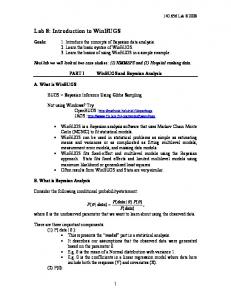
Lab 2 – Introduction to VHDL In this lab you will design, test, and simulate a basic logic circuit using the Quartus II development software. The circuit you will create is a ripple-carry four-bit adder/subtractor using both behavioral and structural VHDL coding. Below is a schematic diagram of the complete circuit. The component make-up includes four full adders and four XOR logic gates. The inputs are two four-bit numbers; A and B, and an add/subtract selection input; Sel. The outputs are four-bit sum; Sum, and a carry-out output; Cout.
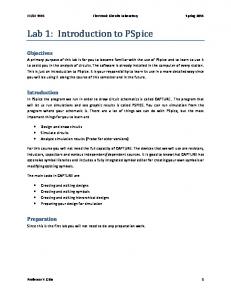
Below is a detailed diagram of the full adder circuit used. It consists of three two-input AND gates, two XOR gates, and one three-input OR gate. The individual gates will be coded separately using behavioral style VHDL, and then stitched together using structural style VHDL to create the full adder. A
XOR2_0
XOR2_0_out
XOR2_1 Sum B AND2_0 Cin AND2_0_out AND2_1_out AND2_2_out
AND2_1
AND2_2
2-1
OR3_1 Cout
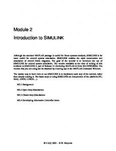
Task 1: Create a New Project 1. Start the Quartus II software. From the Windows Start Menu, select: All Programs → Other Apps → Altera → Quartus II 9.1 → Quartus II 9.1 (32-Bit) 2. Start the New Project Wizard. If the opening splash screen is displayed, select: Create a New Project (New Project Wizard), otherwise from the Quartus II Menu Bar select: File → New Project Wizard. 3. Select the Working Directory and Project Name. Working Directory
H:\Altera_Training\Lab2
Project Name
Lab2
Top-Level Design Entity
Lab2
Click Next to advance to page 2 of the New Project Wizard. Note: A window may pop up stating that the chosen working directory does not exist. Click Yes to create it.
2-2
4. Click Next again as we will not be adding any preexisting design files at this time. 5. Select the family and Device Settings. From the pull-down menu labeled Family, select Cyclone II. In the list of available devices, select EPC235F672C6. Click Next.
6. Click Next again as we will not be using any third party EDA tools.
2-3
7. Click Finish to complete the New Project Wizard.
2-4
Task 2: Create, Add, and Compile Design Files 1. Create a new Design File. Select: File → New from the Menu Bar. Select: VHDL File from the Design Files list and click OK.
2-5
2. Copy and paste the following code into your new VHDL file, then save it by selecting File → Save. Name the file And2 and click Save in the Save As dialog box. Lab 2 – Introduction to VHDL – Two-Input AND Gate Behavioral VHDL Code LIBRARY ieee; USE ieee.std_logic_1164.ALL; ENTITY Gate_And2 IS PORT (x: IN std_logic; y: IN std_logic; F: OUT std_logic); END Gate_And2; ARCHITECTURE Gate_And2_beh OF Gate_And2 IS BEGIN PROCESS(x, y) BEGIN F