Resistors, 5%, ¼ Watt: 100 Ω (1), 270Ω (1), 330 Ω (1) (parts kit). • Oscilloscope ...
worksheet to learn the theory introduced and develop formulas required. 5.
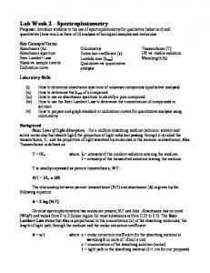
EE 1202 Experiment #2 – Resistor Circuits 1. Introduction and Goals: Demonstrates the voltage-current relationships in DC and AC resistor circuits. Providing experience in using DC power supply, digital multimeter, signal generator, and oscilloscope. 2. Equipment List: Required equipment and components: • Power supply, digital multimeter, oscilloscope, signal generator. • Electronic prototyping board. • Resistors, 5%, ¼ Watt: 100 Ω (1), 270Ω (1), 330 Ω (1) (parts kit). • Oscilloscope probe, 1X setting. • Connecting leads: banana plug, coaxial, and coaxial-to-hook-end. • Calculator (supplied by student). 3. Theory: Ohm’s Law: V=I⋅R; V = voltage in Volts (V), I= current in Amperes (A), R = resistance in Ohms (Ω). Thus Volts = Amperes x Ohms. 3.1. Analogous Example: Current in a resistor is analogous to water flow in a pipe. Voltage is analogous to pressure and pipe diameter to resistance. A narrower pipe restricts water flow, just as higher resistance lowers current flow for a given voltage. Pressure
+ −
Water Current Flow
˗
+ Voltage
3.2. Note: The convention is that “current” is the flow of positive charges from the + DC to – DC. We now know that electrons flow as current from negative to positive, but the convention has persisted. 3.3. In electronics, common current values are milli- (0.001) and micro(0.000001) amps. Common circuit symbols are shown below (Fig. 1). + −
DC Voltage Symbol
+
AC Voltage Symbol
Battery Symbol
Current Flow Symbol
Resistor Symbol
Figure 1. Electrical Symbols Used in Drawing Circuit Schematics. 3.4. Kirchoff’s Current Law: Kirchoff’s Current Law (KCL): the algebraic
EE 1202: Introduction to Electrical Engineering
Experiment #2: Resistor Circuits
sum of currents through any node = zero (NODE = junction of two or more circuit elements). That is, current into a node equals current out. (By convention, node input current is negative, output current is positive.) 0. In Fig. 2, by KCL: − I1 − I 2 − I 3 + I 4 =
NODE
I2
I1 I3
Fig. 2. Current Node Illustrating Kirchoff’s Current Law.
I4
3.5. Kirchoff’s Voltage Law: Kirchoff’s Voltage Law (KVL): the sum of voltages in a loop (see Fig. 3) is zero: −V + IR1 + IR2 + IR3 = 0, or V = IR1 + IR2 + IR3 . R1 V
+ −
R2 R3
I
Fig. 3. Series Resistor Circuit Illustrating Kirchoff’s Voltage Law.
3.6. A DC voltage (battery or power supply) is considered a voltage rise. By convention, voltage rises in a circuit are negative, drops are positive. 4. Pre-Work: Before you go to lab, study this outline and complete the worksheet to learn the theory introduced and develop formulas required. 5. Experimental Procedure: Get out 100, 270, and 330 Ω resistors, two sets of red and black hook-end leads with banana plugs, and a prototyping board. 5.1. If you need help with instruments, leads, or the circuit board, refer to Appendix A. 5.2. Remember to record all measured values below on your data sheet. Power supply leads. Multimeter leads.
Resistor
‒
+
Fig. 4. First Experimental Hook-up. Note: + leads are red.
5.3. Measuring Current in Resistors: Insert the 100 Ω resistor leads into holes on two different parallel rows on the prototype board (Fig. 4). 5.3.1. Turn on bench power and the digital multimeter (DMM).
2
EE 1202: Introduction to Electrical Engineering
Experiment #2: Resistor Circuits
5.3.2. Connect a set of banana-plug leads to the power supply, the red lead to the +20V power output and the black lead to “Common.” 5.3.3. Connect the other two leads to the multimeter as in Fig. 4. 5.3.4. Switch the DMM to DC Voltage (DCV button). 5.3.5. Turn on power supply and select the +20V range. Adjust voltage output until DMM shows +5 volts. Record if not exactly 5 V. 5.3.6. Turn off DMM, detach DMM leads from the resistor, switch DMM to current measurement mode (shift + DCV), and connect DMM in series with the resistor and the black power supply lead Fig. 5). Plug red lead into the current measurement terminal on the DMM. DMM + lead (red)
Power supply − lead.
DMM − lead.
Power supply + lead (red).
Fig. 5. Measuring Current Through a Single Resistor.
5.3.7. Turn on DMM and measure resistor current. Remember: current will be in milliamperes. 5.3.8. Repeat with the other two resistors, checking to make sure the voltage remains 5 V and measuring the current in each case. 5.4. Voltage and Current for the Three Resistors in Series: Mount the 100, 270, and 330 Ω resistors on prototype board so that they are tied in series (Figs. 6 and 7; exact resistor sequence does not matter). R1 R2 V
+ −
R3
I
Power supply leads DMM leads
‒
Fig. 6. Series Resistor Circuit.
Fig. 7. Series Resistor Circuit Test Connection.
+
3
EE 1202: Introduction to Electrical Engineering
Experiment #2: Resistor Circuits
5.4.1. Connect the power supply across all three resistors, setting to 10 VDC. Check voltage across resistors with DMM (in voltage mode). 5.4.2. As above, connect DMM in series, select current measurement, and measure current through all three series resistors. 5.5. Measuring the Voltage and Current for Three Resistors in Parallel: Connect the three resistors in parallel (Figs. 8 and 9). V
+ −
I
−
R1
R2
R3
I1
I2
+
Power supply leads
Fig. 8 Parallel I3 Resistor Circuit
Fig. 9. Parallel Resistor Circuit Test Connection. Note that the upper and lower ends of the resistors are plugged into the same two rows perpendicular to the channel; the lead ends in a common row are thus electrically connected.
DMM leads
5.5.1. (See Fig. 9) Inserting the resistor leads into the same rows connects them in parallel, that is, all three are connected together on each end. 5.5.2. Turn on power supply, set voltage to 5 V, check with DMM. 5.5.3. Set DMM to current measurement and measure total current by putting DMM in series with power supply as shown in Fig. 10. Power supply leads
Fig. 10. Total Current Measurement. (DMM is connected between lower common resistor node and the low side of the power supply).
DMM leads
5.6. AC Voltage/Current Measurements: Ohm’s and Kirchoff’s laws are also true for alternating current (AC). AC voltages include square waves, triangle waves, etc., but we will use only sinusoidal voltages. 5.6.1. Turn on signal generator and oscilloscope (refer to Appendix A as required). Using the 100 Ω resistor, connect a set of BNC-to-hookend leads to the signal generator, and set AC output to sinusoidal, frequency = 1000 Hz, at 10 V, peak-to-peak. Remember to depress 4
EE 1202: Introduction to Electrical Engineering
Experiment #2: Resistor Circuits
the “output” button on the signal generator to output the AC signal to your circuit. Turn DMM to AC measurement. 5.6.2. As AC voltage varies continuously, and the DMM shows a constant number, what is it measuring? It is the “effective,” or “root-mean-square” (RMS) AC voltage, which is the AC equivalent of a DC voltage. The DMM measures this RMS value. Connect the DMM across the resistor (as in Fig. 4, with signal generator replacing power supply); record RMS voltage. 5.6.3. Remove DMM and attach an oscilloscope probe to channel 1 of your oscilloscope. Attach it as shown in Fig. 11 to measure the resistor AC voltage and turn oscilloscope on. Press “Autoscale” button to get the proper picture (refer to the Appendix A for detailed oscilloscope operating instructions). 5.6.4. Once AC voltage is set on the signal generator, check oscilloscope trace. The sinusoidal trace should be close to 10 V, peak-to-peak. Signal generator leads
100 Ω resistor
Fig. 11. AC Waveform Check
Oscilloscope probe
5.6.5. Disconnect oscilloscope leads and connect DMM in series with the resistor (press the “Output” button on the signal generator to turn off AC signal without turning off generator). Change DMM to AC current measurement and turn AC on. Measure/record AC current. 5.6.6. Keeping AC voltage the same (check each time with oscilloscope), measure current in 270 and 330 Ω resistors, recording values. 5.6.7. Repeat the series resistor current measurements of Sec. 5.3, with AC, setting the voltage to 5 V RMS, on the DMM. Record current. 5.6.8. Repeat exercise 5.4 for the three resistors in parallel, using AC current and keeping RMS voltage at 5V. Record total current. 6. Laboratory Area Cleanup: The experiment is complete. Return parts to their kit and replace kit in the cabinet. Make sure your work area is clean. 7. Writing the Laboratory Report: Follow report guidelines in your manual. Perform the following analyses and list the results as a part of your report. 7.1. Draw schematics (electrical diagrams in symbol form) of the series and parallel resistor circuits used in your measurements. 7.2. Since V=IR, then R=V/I. Use this relation to calculate the resistance of 5
EE 1202: Introduction to Electrical Engineering
Experiment #2: Resistor Circuits
each of the three resistors, based on your DC and AC measurements. Use the table in the data sheet to compare nominal (labeled) resistor values with your calculated values using the DC and AC measurements. Note that since the resistors that you are using are manufactured to a 5% tolerance, a 100 Ω resistor, for example, could be anywhere from 95 Ω to 105 Ω. Discuss how your calculated values differ from the nominal (that is, labeled) resistor values. 7.3. In your worksheet, you developed formulas for equivalent resistances of three series resistors and three parallel resistors. Using the formulas, calculate equivalent series and parallel resistances of the three resistors, using your calculated DC resistor values. 7.4. Use the series resistance table in your data sheet to compare equivalent resistance of the series resistors, showing the calculated value using the formula developed in the worksheet and the values calculated from the measured DC and AC current and voltage. 7.5. Use the parallel resistance table in your data sheet to compare equivalent resistance of the parallel resistors, showing the calculated value using the formula developed in the worksheet and the values calculated from the measured DC current and voltage. 7.6. Discuss any differences in values between calculated and measured series and parallel currents.
6
EE 1202: Introduction to Electrical Engineering
Experiment #2: Resistor Circuits
Experiment #2 Data Sheet DC Circuit Measurements: 1. Nominal value:
100 Ω resistor
270 Ω resistor 330 Ω resistor
2. Current at 5VDC:
100 Ω resistor
270 Ω resistor 330 Ω resistor
____________ 100 Ω resistor
____________ ____________ 270 Ω resistor 330 Ω resistor
____________
____________ ____________
3. Actual value (R=V/I):
4. Current reading in series resistors (Amperes): ____________ (at 10 VDC) 5. Calculated series resistance of three resistors using ____________ values calculated in 3, above. 6. Calculated series resistance of three resistors (V/I): ____________ from series V/I measurement. 7. Calculated resistance of three resistors in parallel: ____________ Using values calculated in 3, above. 8. Total current to all three parallel resistors (Amps): ____________ (5VDC) 9. Calculated resistance of three parallel resistors (V/I): ____________ from parallel V/I measurement. AC Circuit Measurements: 10.RMS AC V/I in 100 Ω resistor at 10 V, p-p:
________ / ________
11.RMS AC V/I in 270 Ω resistor at 10 V, p-p:
________ / ________
12.RMS AC V/I in 330 Ω resistor at 10 V, p-p:
________ / ________
13.RMS AC V/I, series resistors, 5VRMS (nominal): ________ / ________ 14.RMS AC V/I, parallel resistors, 5VRMS (nom.):
7
________ / ________
EE 1202: Introduction to Electrical Engineering
Experiment #2: Resistor Circuits
Experiment #2 Data Sheet (Page 2) 15.Comparative Values of Individual Resistors: Nominal Value (Ω) 100 Calculated Resistor Value (V/I), Using DC Calculated Resistor Value (V/I), Using AC 16.Comparative Values of Series Resistors: Series Equivalent of Measured Resistor Values (Using Formula Developed in Worksheet and values calculated in DC measurements in 15, above) Calculated Series Resistor Values (DC V/I) Calculated Series Resistor Values (AC V/I) 17.Comparative Values of Parallel Resistors: Parallel Equivalent of Measured Resistor Values (Using Formula Developed in Worksheet and values calculated in DC measurements in 15, above) Calculated Parallel Resistor Values (DC V/I) Calculated Parallel Resistor Values (AC V/I)
8
270
330
EE 1202: Introduction to Electrical Engineering
Experiment #2: Resistor Circuits
Experiment #2 Worksheet Refer to Experiment #2 theory to answer the questions below. 1. Using Ohm’s Law, find the resistor values, given the voltages and currents: V=10V, I=20 mA, R = _________________________ Ω. V=5V, I=40 mA, R = _________________________ Ω. V=12V, I=97 mA, R = _________________________ Ω. 2. Equivalent resistance of series resistors: Consider the circuits below. +V1 = IR1
─V
+ −
R1
+V2 = IR2 R2
R3
─V
+V3 = IR3
+ −
RE
+VRE = IRE
I I There is a resistance, RE , that is equivalent to the three series resistors. Assuming the same voltage in both loops, then since RE is equivalent to the three series resistors, the current I is the same in each loop. Since the two circuits must obey Kirchhoff’s loop voltage law, = I V / R= V / ( R1 + R2 + R3 ) , or E V/R = V / ( R1 + R2 + R3 ) . Given the second equation above, solve for RE . (The E V term on both sides is easily eliminated.) 3. Equivalent resistance of parallel resistors: The two circuits below are also equivalent. I I RE V
+ −
R1
R2 I1
R3 I2
V
I3
+ −
? Ω (equivalent resistance)
I Again, there is some resistance, RE , that is equivalent to the three parallel resistors. Since the voltage is the same in each loop, then I must be the same in each. By KCL, I = I1 + I 2 + I 3 , so that: V / RE = (V / R1 ) + (V / R2 ) + (V / R3 ) . Solve this equation for RE . Once again, the voltage is easily eliminated from both sides of the equation.
9