CCNA Exploration. Wireless Configuration: Basic Wireless Concepts and
Configuration Lab 7.5.3: Troubleshooting Wireless Configuration. S1. VLAN 5.
5.5.5.1.
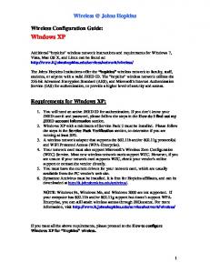
Lab 7.5.3: Troubleshooting Wireless Configuration (Instructor Version) Topology Diagram
Addressing Table Device
Default Gateway
Interface
IP Address
Subnet Mask
Fa0/0.5
5.5.5.10
255.255.255.0
N/A
Fa0/0.10
192.168.10.1
255.255.255.0
N/A
Fa0/0.11
11.11.11.1
255.255.255.0
N/A
Fa0/0.18
18.18.18.1
255.255.255.0
N/A
Lo0
10.1.1.1
255.255.255.252
N/A
WAN
192.168.10.2
255.255.255.0
192.168.10.1
LAN/Wireless
192.168.20.1
255.255.255.0
N/A
WAN
192.168.10.3
255.255.255.0
192.168.10.1
LAN/Wireless
192.168.30.1
255.255.255.0
N/A
PC1
NIC
11.11.11.10
255.255.255.0
11.11.11.1
PC4
NIC
18.18.18.10
255.255.255.0
18.18.18.1
R1
WRS2
WRS3
All contents are Copyright © 1992–2007 Cisco Systems, Inc. All rights reserved. This document is Cisco Public Information.
Page 1 of 9
CCNA Exploration Wireless Configuration: Basic Wireless Concepts and Configuration
Lab 7.5.3: Troubleshooting Wireless Configuration
S1
VLAN 5
5.5.5.1
255.255.255.0
N/A
S2
VLAN 5
5.5.5.2
255.255.255.0
N/A
S3
VLAN 5
5.5.5.3
255.255.255.0
N/A
Scenario In this lab, a basic network and wireless network have been configured improperly. You must find and correct the misconfigurations based on the minimum network specifications provided by your company. Here are the configurations to load into your router and switches. [Instructors Note: Missing configurations in red and incorrect configurations in strike-through red] R1 Configuration hostname R1 ! interface Loopback0 ip address 10.1.1.1 255.255.255.0 ! interface FastEthernet0/0 no ip address duplex auto speed auto no shutdown ! interface FastEthernet0/0.5 encapsulation dot1Q 5 ip address 5.5.5.10 255.255.255.0 ! interface FastEthernet0/0.10 encapsulation dot1Q 10 ip address 192.168.11.1 255.255.255.0 ip address 192.168.10.1 255.255.255.0 ! interface FastEthernet0/0.11 encapsulation dot1Q 11 ip address 11.11.11.1 255.255.255.0 ! interface FastEthernet0/0.18 encapsulation dot1Q 18 ip address 18.18.18.1 255.255.255.0 ! ip route 192.168.20.0 255.255.255.0 192.168.10.2 ip route 192.168.30.0 255.255.255.0 192.168.10.3 ip route 192.168.20.0 255.255.255.0 192.168.10.3 ip route 192.168.30.0 255.255.255.0 192.168.10.2 ! line con 0 exec-timeout 0 0 logging synchronous ! end
All contents are Copyright © 1992–2007 Cisco Systems, Inc. All rights reserved. This document is Cisco Public Information.
Page 2 of 9
CCNA Exploration Wireless Configuration: Basic Wireless Concepts and Configuration
Lab 7.5.3: Troubleshooting Wireless Configuration
Switch 1 Configuration hostname S1 ! vtp mode transparent ! vlan 5,10-11 vlan 18 ! interface FastEthernet0/1 switchport trunk allowed vlan 5,10,11,18 switchport mode trunk switchport trunk native vlan 5 ! interface FastEthernet0/2 switchport trunk allowed vlan 5,10,11,18 switchport mode trunk switchport trunk native vlan 5 ! interface FastEthernet0/3 switchport trunk allowed vlan 5,10,11,18 switchport mode trunk switchport trunk native vlan 5 ! interface FastEthernet0/4 switchport trunk allowed vlan 5,10,11,18 switchport mode trunk switchport trunk native vlan 5 ! interface FastEthernet0/5 switchport mode trunk switchport trunk native vlan 5 ! interface Vlan5 ip address 5.5.5.1 255.255.255.0 no shutdown ! line con 0 exec-timeout 0 0 logging synchronous ! End
Switch 2 Configuration hostname S2 ! vtp mode transparent ip subnet-zero ! vlan 5,10-11,18 ! interface FastEthernet0/1
All contents are Copyright © 1992–2007 Cisco Systems, Inc. All rights reserved. This document is Cisco Public Information.
Page 3 of 9
CCNA Exploration Wireless Configuration: Basic Wireless Concepts and Configuration
Lab 7.5.3: Troubleshooting Wireless Configuration
switchport trunk allowed vlan 5,10,11,18 switchport mode access switchport mode trunk switchport trunk native vlan 5 ! interface FastEthernet0/2 switchport trunk allowed vlan 5,10,11,18 switchport mode access switchport mode trunk switchport trunk native vlan 5 ! interface FastEthernet0/3 switchport trunk allowed vlan 5,10,11,18 switchport mode access switchport mode trunk switchport trunk native vlan 5 ! interface FastEthernet0/4 switchport trunk allowed vlan 5,10,11,18 switchport mode access switchport mode trunk switchport trunk native vlan 5 ! interface FastEthernet0/7 switchport access vlan 10 ! interface FastEthernet0/11 switchport access vlan 11 switchport mode access switchport port-security mac-address sticky switchport port-security mac-address sticky 0336.5b1e.33fa !!! Note: While this may appear in the running configuration after configuring sticky mac-address port security, unless PC1 and PC4 have these addresses, they will be denied access. The student must remove these incorrectly pre-set sticky addresses and have the switch properly and dynamically discover the PC1 and PC4 addresses. ! interface FastEthernet0/18 switchport access vlan 18 switchport mode access switchport port-security switchport port-security mac-address sticky switchport port-security mac-address sticky 022c.ab13.22fb ! interface Vlan1 no ip address shutdown ! interface Vlan5 ip address 5.5.5.2 255.255.255.0 no shutdown ! line con 0 exec-timeout 0 0 logging synchronous !
All contents are Copyright © 1992–2007 Cisco Systems, Inc. All rights reserved. This document is Cisco Public Information.
Page 4 of 9
CCNA Exploration Wireless Configuration: Basic Wireless Concepts and Configuration
Lab 7.5.3: Troubleshooting Wireless Configuration
End
Switch 3 Configuration hostname S3 ! vtp mode transparent ! vlan 5,10-11,18 ! interface FastEthernet0/1 switchport trunk allowed vlan 5,10,11,18 switchport mode trunk switchport trunk native vlan 5 ! interface FastEthernet0/2 switchport trunk allowed vlan 5,10,11,18 switchport mode trunk switchport trunk native vlan 5 ! interface FastEthernet0/3 switchport trunk allowed vlan 5,10,11,18 switchport mode trunk switchport trunk native vlan 5 ! interface FastEthernet0/4 switchport trunk allowed vlan 5,10,11,18 switchport mode trunk switchport trunk native vlan 5 ! interface FastEthernet0/7 switchport access vlan 10 ! interface Vlan1 no ip address no ip route-cache shutdown ! interface Vlan5 ip address 6.6.6.3 255.255.255.0 ip address 5.5.5.3 255.255.255.0 no shutdown ! line con 0 exec-timeout 0 0 logging synchronous ! end
Wireless Router Network Requirements While troubleshooting WRS2 and WRS3, ensure that at least the following capabilities exist: 1. 2.
Connections via the IP addresses shown in the topology diagram. More than 30 clients can get an IP address through DHCP at a single time.
All contents are Copyright © 1992–2007 Cisco Systems, Inc. All rights reserved. This document is Cisco Public Information.
Page 5 of 9
CCNA Exploration Wireless Configuration: Basic Wireless Concepts and Configuration
3. 4. 5. 6. 7. 8. 9.
Lab 7.5.3: Troubleshooting Wireless Configuration
A client can have a DHCP address for at least 2 hours. Clients using both B and G wireless network modes can connect, but N clients cannot. Wireless clients must be authenticated using WEP with a key of 5655545251. Traffic between PC2 and PC3 must take the most efficient route possible. Ping requests coming from outside WAN ports of the Linksys routers to their inside LAN/wireless IP addresses (192.168.30.1) must be successful. DHCP must not give out IP addresses in a range that includes the addresses for PC2 and PC3. The two wireless networks must not interfere with each other.
Wireless Network Solution Record your solution below.
Errors on WRS2 WRS2 should have an IP address of 192.168.10.2 and a default gateway of 192.168.10.1, instead of the following: (violates condition #1)
DHCP is configured to give out addresses in the range of 192.168.20.2 – 65. The PC2 address 20.2 falls in this range. While DHCP has reserved the 20.2 address and will not give it out via DHCP to any computer but PC2, it is best practice to only give out addresses in an unused range. Changing the start IP address to above 20.2 circumvents this problem. (violates condition #8)
In the Advanced Routing tab, the static route to the WRS3 clients is configured incorrectly. The gateway of 192.168.10.1 is the inefficient route we are trying to avoid. Instead of pointing toward R1, the static route should point directly to WRS3 with the IP address 192.168.10.3. Change Gateway to this address. (Not doing this violates condition #6)
All contents are Copyright © 1992–2007 Cisco Systems, Inc. All rights reserved. This document is Cisco Public Information.
Page 6 of 9
CCNA Exploration Wireless Configuration: Basic Wireless Concepts and Configuration
Lab 7.5.3: Troubleshooting Wireless Configuration
In the Security tab, Filter Anonymous Internet Requests must be unchecked if pings coming from outside the router’s LAN/wireless network to 192.168.20.1 are to be successful. Make sure that it is unchecked. (violates condition #7)
Errors on WRS3 DHCP is configured to give out only two IP addresses at a time and for only 40 minutes. (violates conditions #2 and #3)
Change the Maximum Number of Users to at least 30 and the Client Lease Time to at least 120 minutes. In the Advanced Routing tab, the static route that is configured to efficiently route between WRS2 and WRS3 is incorrect. (violates condition #6)
All contents are Copyright © 1992–2007 Cisco Systems, Inc. All rights reserved. This document is Cisco Public Information.
Page 7 of 9
CCNA Exploration Wireless Configuration: Basic Wireless Concepts and Configuration
Lab 7.5.3: Troubleshooting Wireless Configuration
Instead of the destination being 192.168.67.0, it should be 192.168.30.0. In the Wireless Security tab, RADIUS authentication is configured, but clients are supposed to authenticate via WEP. (violates condition #5)
Change the Security Mode to WEP and use a key of 5655545251.
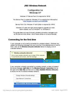
Wireless Connectivity Issues Conditions 4 and 9 call for a wireless network mode of B/G on non-overlapping channels. The configuration on WRS2 is as follows:
All contents are Copyright © 1992–2007 Cisco Systems, Inc. All rights reserved. This document is Cisco Public Information.
Page 8 of 9
CCNA Exploration Wireless Configuration: Basic Wireless Concepts and Configuration
Lab 7.5.3: Troubleshooting Wireless Configuration
The configuration on WRS3 is as follows:
Change the network mode on both routers to be B/G and make sure that the channels do not overlap, for example, one could be on channel 1 and another on channel 6.
All contents are Copyright © 1992–2007 Cisco Systems, Inc. All rights reserved. This document is Cisco Public Information.
Page 9 of 9