Proceedings on the Second International Conference on the Application of Physical Modelling to Port and Coastal Protection
LABORATORY TESTS ON PERFORMANCE OF A COASTAL PROTECTION PROJECT IN AGROPOLI EDOARDO BENASSAI (1), MARIO CALABRESE (1), MARIANO BUCCINO (1), PASQUALE DI PACE (1), FRANCESCO PASANISI (2), CARLO TEBANO (2) and FRANCESCO ZARLENGA (3) (1) University of Napoli Federico II, Department Hydraulic, Geotechnical and Environmental Engineering, Via Claudio 21, Napoli, 80125, Italy.
[email protected],
[email protected],
[email protected],
[email protected] (2) ENEA, Department Environment, Global Changes and Sustainable Development, Portici Research Center, Località Granatello, Portici (NA), 80055, Italy.
[email protected],
[email protected] (3) ENEA, Department Environment, Global Changes and Sustainable Development, Casaccia Research Center, Via Anguillarese 301, Santa Maria di Galeria (Roma), 00123, Italy.
[email protected]
An experimental study was commissioned to evaluate, at design stage, the performance of a beach nourishment protected by a submerged rubble mound breakwater with gaps in Agropoli (Gulf of Salerno). Experiments were performed in the 3D wave basin at University of Napoli Federico II. Results showed that under extreme wave conditions no significant loss of material is to be expected through the gaps of the structure. Measured post-nourishment coastline retreats due to cross-shore processes were comparable with prediction obtained using mathematical models. Keywords: Beach nourishment, submerged breakwater, movable-bed model.
1. Introduction Beach nourishments protected by submerged breakwaters are very common and appreciated coastal protection measures. They appear to be a good compromise among different needs, i.e. enhancing the beach, mitigating incident wave climate and preserving coastal environment and landscape. Nevertheless, despite recent progress, the hydraulic response of low-crested barriers and shoreline evolution is still affected by uncertainties and many cases are reported in which the use of a submerged barrier had a negative impact on littoral. Dean et al. (1997) described the emblematic case of Palm Beach, Florida, where a submerged narrow-crested breakwater (known as ‘PEP reef’) caused an additional erosion rate above the background erosion of about 130%; Ranasinghe and Turner (2006) summarized observations of submerged structures in USA, Italy and Australia, and noticed that net erosion was reported at seven of the ten examined cases. More in general, wave transmission at submerged breakwater is a complex process, incorporating the effects of wave transformation due to depth change, wave breaking, friction, filtration inside the barrier, overtopping and gradients in radiation stresses which significantly affect hydraulic circulation. In a 2-D framework, two main processes can be identified: the former is the wave energy reduction owing to wave reflection, friction and wave breaking at breakwater, the latter is the wave spectrum change due to non-linear processes above the barrier. The first matter has been deeply investigated in the past, and many empirical formulae have been proposed for prediction of transmission coefficient (d’Angremond et al., 1996; Seabrook and Hall, 1998; van der Meer et al., 2005). The second process, due to non linear effects at barrier, induces harmonic generation and wave spectrum spreading toward higher frequencies (Massel, 1983; Grue, 1992; Ohyama and Nadaoka, 1994; Yamashiro et al., 1999; van der Meer et al., 2000; Pasanisi et al., 2007; Buccino et al., 2008). (DALRYMPLE, 1978)
(BROWDER ET AL., 1996)
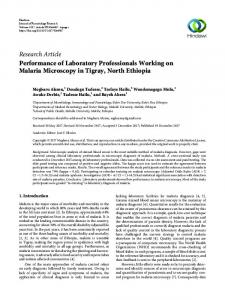
Figure 1. General circulation patterns for single and segmented submerged barriers
In a 3-D framework, other processes are to be considered, including the effect of angle of wave attack on transmission coefficient, the change in wave direction due to wave-barrier interaction, the influence of wave short-crestedness. A key issue 1
COASTLAB 2008
is correctly modelling the circulation currents due to gradients in wave set-up and radiation stress induced by wave-barrier interaction, in particular near the breakwater discontinuities. Namely, at breakwater tips, or at gaps in segmented structures, an offshore-directed current is generated, which, beside danger for swimming, can induce scour and sediment loss and lead to failure of nourishment project. Fig. 1 shows typical circulation patterns for a single barrier (Browder et al., 1996) and a segmented barrier (Dalrymple, 1978). Despite recent progress (Johnson et al., 2005) mathematical models can still be affected by uncertainties, that can justify, for larger projects, the use of physical models. The present paper describes experimental tests performed in 3D wave basin aimed at evaluation, at design stage, of the performance of a beach nourishment protected by a submerged shore-parallel rubble mound breakwater with gaps. Main aim of the work was to model beach profile evolution under wave attack and verify if sediment loss is to be expected through the gaps of the barrier. 2. Overview of the project The coast between Cape San Marco and the mouth of Testene River, in Agropoli, at southern end of the Gulf of Salerno, in Southern Italy, Thyrrenian Sea (Fig. 2), is a straight, narrow, sandy beach, about 1.5 km long and 20-25 m wide. The littoral showed, over the last decades, a significant erosive trend, with a great concern for the safety of the coast road and other structures located landwards.
NAPOLI
ISCHIA
Gulf of Napoli SALERNO
CAPRI
Gulf of Salerno
Agropoli Project Area
Figure 2. Geographical setting
A coastal protection project was thus proposed, consisting of an artificial beach nourishment protected by a shore-parallel submerged rubble mound breakwater located 120 m offshore (considering original coastline), at about 3.5 m depth. Three gaps were planned along the structure, each one 20.0 m wide, to allow navigation and ensure water circulation. Finally, semisubmerged groins were planned at both ends and in the middle of the barrier. In Fig. 3 a plan of the project is reported. Native sand mean diameter D50 is 0.20 mm, whilst planned nourishment sand is a little coarser (D50=0.30 mm). Nourishment profile (Fig. 4) is composed of three different stretches: the first, horizontal, is 15.0 m long, with elevation 1.0 m over SWL; the second stretch, with slope 1:15, extends 15.0 m in offshore direction as far as nourishment profile intersects SWL; The third stretch, submerged, has a 1:20 slope. Altogether, post-nourishment coastline advance is 30.0 m. At design stage, an expected 10.0 m long-term erosion was predicted using mathematical models, resulting in a planned net 20.0 m 2
Proceedings on the Second International Conference on the Application of Physical Modelling to Port and Coastal Protection
coastline advance. As regards the barrier cross-section, the freeboard above the crest is 0.70 m; seaward slope of the barrier is1:5, rear slope is 1:2 and crest width is 8.0 m (Fig. 5).
Testene River
N
submerged breakwater gap
Cape San Marco
artificial nourishment actual beach 0
100 200 300 400 500 m
Figure 3. Plan of the coastal protection project in Agropoli
30.00
nourishment profile
15.00
actual profile
15.00
Figure 4. Original and post-nourishment beach profile
8.00
8.00
6.00
SWL -0.70 stones 1-3 t stones 50-500 kg
-2.50
-3.50
Figure 5. Cross-section of the submerged breakwater
3. Experimental facilities, instrumentation and techniques Experiments were performed in the 3D wave basin at University of Napoli Federico II, Department of Hydraulic, Geotechnical and Environmental Engineering. The basin is rectangular with dimensions 18.0x36.0 m, with height 1.2 m. Facilities was recently renovated and equipped with up-to-date instrumentation supplied by HR Wallingford in the frame of a research project ENEA-University of Napoli. Waves are generated by a multi-element wavemaker, made of 16 electrically driven paddles (Fig. 6), each 0.75 m wide. The width of the wave front is 12.0 m. The system allows to generate both regular and irregular sea-states, according to the most used wave spectra, or customized wave spectrum; different wave directions, including multidirectional and short-crested conditions can be generated. Lateral steel wave guides are present at both sides of the wavemaker. Surface elevation data are measured using twin-wire resistance wave gauges. Beach profile are measured along different transects using a precision bed profiler with touch-sensitive probe, with accuracy ±1.0 mm. 3
COASTLAB 2008
Figure 6. Multi-element wavemaker at University of Napoli Federico II
4. The physical model Length scale factor was chosen considering the extension of the project and the obvious need to avoid too large factors, loosing accuracy and increasing scale effects. The morphological features of the littoral, the quite regular bathymetry and incident wave conditions allowed to reduce the investigation area, without loosing physical meaning. Thus, a geometrical scale factor 1:40 was chosen. Froude similarity was adopted for time scale factors. The major axis of wave basin was oriented along direction 275°N, approximately perpendicular to coastline and bathymetric contours (Fig. 7). Scale factor for sediment grain sizes was chosen based on the conservation of the fall speed parameter, also known as Dean number:
H ω T
[1]
being H the wave height, T the wave period and ω the vertical fall speed of the sediment in fluid. Sediment fall speed was derived using Hallermeier empirical formula (Hughes, 1993). Dimensionless number in Eq. 1 expresses the ratio between the sediment fall time and the wave period and plays a key role in sediment processes. If the sediment fall time is large compared to the wave period, the sediment grain would remain in suspension whilst, if the fall time is equal or lower than the wave period, bed load transport should be expected. The scaling criterion based on the conservation of the fall speed parameters appears to be sufficiently realistic in modelling sediment processes in turbulence-dominated energetic nearshore regions, where wave breaking induce a large sediment suspension; the method was proven to give a realistic description of the equilibrium beach profile owing to cross-shore modelling. Bathymetry, structure geometry, original and nourishment beach profile were reproduced at scale model according to project graphs and documentation. Water depth in the basin was 0.30 m, corresponding to 12.0 m at prototype scale. Incident wave climate was transferred from deep water to wavemaker depth using a mathematical model based on the conservation equation for the spectral wave action density (Holtuijsen et al., 1989). According to indication provided by commitment, two different layouts were tested, corresponding to different steps of works execution: A. Submerged barrier and original beach (without nourishment); B. Submerged barrier and artificial nourishment. Main aim of tests for layout A was to verify, at a first step of work execution, the efficiency of the wave barrier for costal protection, in terms of wave height, run-up and coastline stability, prior to beach fill and shoreline advance. Main aim of tests for layout B, besides verification of wave energy reduction, was to verify the stability of the beach nourishment under severe wave attack, in order to evaluate risk of erosion and sediment loss through the gap of the submerged barrier.
4
Proceedings on the Second International Conference on the Application of Physical Modelling to Port and Coastal Protection
Cape San Marco
N
Testene River
Figure 7. Overview of the physical model
The analysis of incident wave climate indicated that the littoral is mainly subjected to cross-shore modelling. Direction of the mean vectorial wave energy flux at wavemaker depth is 274.9°N, which approximately corresponds to shoreperpendicular direction; besides, from time series observations, the offshore directions of most severe wave events are comprised in the sector 260-280°N. Consistently with the assumption of cross-shore modelling, extreme wave conditions were used for tests, derived from historical data fitted to Gumbel statistical distribution; according to the project, a return period TR=30 years was adopted. Duration of extreme waves attack was chosen equal to 2.0 hours at model scale, corresponding to 12.6 hours at prototype scale; the assumption is consistent with the maximum storm duration derived from historical data. For tests with beach nourishment (layout B), in order to simulate beach profile modelling under ordinary wave climate, prior to extreme waves, milder wave conditions were simulated, derived from wave climate analysis, according to criterion of so-called ‘morphological waves’; duration of wave attack for ordinary waves was 15,000s (4.2 hours), corresponding to about 26 hours at prototype scale. JONSWAP spectrum was adopted for wave energy distribution at wavemaker; Peak period Tp was derived from significant wave period Ts using the well-known relation:
T p = 1.05 Ts
[2]
Incident wave direction at wavemaker was 275°N for all tests (normal wave attack). In Table 1 and Table 2 the incident wave conditions for layouts A and B are summarized. Prior to tests for layouts A and B, calibration tests were performed to achieve the best agreement among target and measured wave spectra at wavemaker, obtained by an appropriate choice of a ‘gain’ parameter in theoretical wavemaker transfer function. As regards wave data acquisition, 7 wave probes were used, as specified in the following: • 3 wave gauges in front of the wave maker; • 2 wave gauges at seaward tip of the barrier (at current section and gap); • 2 wave gauges at landward tip of the barrier (at current section and at gap); Sample frequency was 20 Hz. Surface elevation data were analyzed in both time and frequency domain; wave spectra 5
COASTLAB 2008
and the main spectral parameters were estimated, as well as main statistical wave parameters. Measured beach profiles were measured along 4 transects, delimited offshore by the breakwater toe and inshore by the beach limit, approximately 0.50 m (at model scale) from original coastline (20.0m at prototype scale). Fig. 8 illustrates the positions of wave probes and transects along which beach profiles were measured. Table 1. Wave conditions at wavemaker for tests with layout A (original beach and submerged barrier) ESTREME WAVES
model scale
prototype scale
duration of wave attack (hours)
2.00
12.65
significant wave height – Hs (m)
0.129
5.140
peak period -Tp (s)
1.806
11.424
peak frequency - fp (Hz)
0.554
0.088
Table 2. Wave conditions at wavemaker for tests with layout B (artificial nourishment and submerged barrier) model scale
prototype scale
duration of wave attack (hours)
4.2
26.3
significant wave height – Hs (m)
0.032
1.29
peak period -Tp (s)
0.882
5.310
peak frequency - fp (Hz)
1.134
1.134
2.00
12.65
B1- ORDINARY WAVES
B2- ESTREME WAVES duration of wave attack (hours) significant wave height – Hs (m)
0.129
5.140
peak period -Tp (s)
1.806
11.424
peak frequency - fp (Hz)
0.554
0.088
transect a-a
wavemaker
1
4
5
transect b-b transect c-c
2 6
7 groin
3
actual coastline
post-nourishment coastline
submerge d barrier
transect d-d
Figure 8. Position of wave probes (numbered from 1 to 7) and measured beach profiles
5. Summary of main results In Fig. 9 and Fig. 10, pictures taken during tests are shown. For lower wave heights, wave breaking was noticed at barrier, whilst, for higher waves, breaking took place offshore of the barrier, closer to wavemaker. Due to accurate wavemaker 6
Proceedings on the Second International Conference on the Application of Physical Modelling to Port and Coastal Protection
calibration, a good agreement was observed among measured and target spectra at wavemaker, despite a limited superharmonic generation (Fig. 11). For both layout A and B, consistently with previous literature (Loveless and MacLeod, 1999), a strongly offshoredirected current was noticed at gap of the barrier. Circulation patterns were visualized using a fine calcium carbonate powder as tracer. Local excavation was observed around the heads of the barrier and sedimentation at gap (Fig. 12).
Barrier gap
Wave probes at leading and trailing side of the barrier
Figure 9. Picture taken during test. Two couple of wave probes are visible at leading and trailing side of the submerged breakwater
Figure 10. Picture taken from the beach, while running test A
7
COASTLAB 2008
0.006
target spectrum measured spectral densities
0.005
E (m2 s)
0.004
0.003
0.002
0.001
0.000 0.00
0.25
0.50
0.75
1.00
1.25
1.50
1.75
2.00
f (Hz) Figure 11. Comparison among target spectrum and measured spectral densities
offshore side sedimentation
e or fsh f o
e si d
current patterns landward side
erosion
Figure 12. Circulation patterns and sediment processes at the gap of the barrier
Beach profile measurements for tests with layout A, with original beach profile, suggested that submerged breakwater provides a sufficient mitigation of incident wave energy, resulting in a limited beach profile modification under extreme wave conditions. A limited profile excavation was noticed immediately under the still water level, with deposition at the inshore toe of the barrier or inside the gap; however, no significant coastline movements were observed. As regards layout B, as expected, beach nourishment profile showed a significant modification under extreme waves attack. Main features of observed profile modelling were: • coastline retreat, varying in the range 8.0-10.0 m, with stronger erosion behind the gap of the barrier; • steeper wave profile close to still water level, compared to initial post-nourishment configuration; • sediment deposition in inshore zone, with formation of a sand bar above the still water level; • limited sediment deposition at barrier toe and inside the gap. Altogether, measured coastline retreat is consistent with expected long-term profile erosion predicted at previous design stage using mathematical models (about 10.0 m). In Fig. 13 and Fig. 14 measured original and nourishment beach profiles before and after tests are illustrated. Observed beach nourishment profile evolution is similar to what typically reported in previous laboratory and field studies for protected beaches. Fig. 15 shows, for comparison purpose, results reported by Sorensen and Reil (1988); analogous results were obtained by Ferrante et al. (1992) from in-situ monitoring of beach nourishment at Lido di Ostia (Roma). 8
4.0
0.100
3.0
0.075
2.0 1.0 0.0 -1.0 -2.0
z (m) - model scale
z (m) - prototype scale
Proceedings on the Second International Conference on the Application of Physical Modelling to Port and Coastal Protection
original beach profile nourishment profile before test nourishment profile after test
0.050 0.025
SWL
0.000 -0.025 -0.050
-3.0
-0.075
-4.0
-0.100 -4.00
-3.50
-3.00
-2.50
-160.0 -150.0 -140.0 -130.0 -120.0 -110.0 -100.0
-2.00
-1.50
-1.00
x (m) - mod el scale
-90.0
-80.0
-70.0
-60.0
-50.0
-40.0
-0.50
-30.0
-20.0
0.00
-10.0
0.0
0.50
10.0
20.0
x (m) - prototype scale
4.0
0.100
3.0
0.075
2.0 1.0 0.0 -1.0 -2.0
z (m) - model scale
z (m) - prototype scale
Figure 13. Measured beach profiles leeward of the barrier
original beach profile nourishment profile before test nourishment profile after test
0.050 0.025
SWL
0.000 -0.025 -0.050
-3.0
-0.075
-4.0
-0.100 -4.00
-3.50
-3.00
-2.50
-2.00
-1.50
-1.00
x (m) -model scale
-160.0 -150.0 -140.0 -130.0 -120.0 -110.0 -100.0
-90.0
-80.0
-70.0
-60.0
-50.0
-40.0
x (m) - prototype scale
Figure 14. Measured beach profiles at the barrier gap
Figure 15. Experimental results reported by Sorensen and Reil (1988)
9
-0.50
-30.0
-20.0
0.00
-10.0
0.0
0.50
10.0
20.0
COASTLAB 2008
6. Conclusions Experimental results suggested that the proposed protection project can be considered effective for costal protection at Agropoli site. Submerged barrier showed a good performance in wave energy mitigation. Shoreline response can be considered good for both tested configurations; for layout A (with original beach profile), no significant erosion was observed, whilst for layout B (with beach nourishment profile) measured coastal erosion is consistent with long-term prediction obtained using mathematical models. Acknowledgements Experimental study was commissioned by Autorità di Bacino Regionale Sinistra Sele, local Authority for territorial planning and regulation at river basin scale.
References Browder, A.E., Dean, R.G., Chen, R. 1996. ‘Performance of a submerged breakwater for shore protection’, Proceedings of 25th International Conference on Coastal Engineering. Buccino, M., Calabrese, M., Ciardulli, F., Pasanisi, F. 2008. ‘2nd order wave transmission past a submerged breakwater’, Proceedings of 31st International Conference on Coastal Engineering, in press. Dalrymple, R.A. 1978. ‘Rip currents and their causes’, Proceedings of 16th International Conference on Coastal Engineering. d’Angremond, K., van der Meer, J.W., de Jong, R.J. 1996. ‘Wave transmission at low crested structures’, Proceedings of 25th International Conference on Coastal Engineering, 3305–3318. Dean, R.G., Chen, R., Browder, A.E. 1997. ‘Full scale monitoring study of a submerged breakwater, Palm Beach, Florida, USA’, Coastal Engineering, 29, 291-315. Ferrante, A., Franco, L., Boer, S. 1992. ‘Modelling and monitoring of a perched beach at Lido di Ostia (Rome)’, Proceedings of 23rd International Conference on Coastal Engineering, 3305-3318. Grue, J. 1992. ‘Nonlinear water waves at a submerged obstacle or bottom topography’, Journal of Fluid Mechanics, 244, 455-476. Holthuijsen, L.H., Booij, N., Herbers, T.H.C. 1989. ‘A prediction model for stationary, short-crested waves in shallow water with ambient currents’, Coastal Engineering, 13, 23-54. Hughes, S.A. 1993. ‘Physical models and laboratory techniques in coastal engineering’, World Scientific, Singapore, ISBN 9810215401. Johnson, H.K., Karambas, T.V., Avgeris, I., Zanuttigh, B., Gonzalez-Marco, D., Caceres, D. 2005. ‘Modelling of waves and currents around submerged breakwaters’, Coastal Engineering, 52, 949-969. Loveless, J., MacLeod, B. 1999. ‘The Influence of Set-Up Currents Movement behind Detached Breakwater’, Proceedings of Coastal Sediments 99, 2026-2041. Massel, S.R. 1983. ‘Harmonic generation by waves propagating over a submerged step’, Coastal Engineering, 7, 357-380. Ohyama, T. and Nadaoka, K. 1994. ‘Transformation of a nonlinear wave train passing over a submerged shelf without breaking’, Coastal Engineering, 24, 1-22. Pasanisi, F., Buccino, M., Calabrese, M. 2007. ‘Macrofeatures and engineering properties of wave breaking at submerged rubble-mound breakwaters’, Proceedings of 5th International Conference on Coastal Structures, in press. Ranasinghe, R., Turner, I.L. 2006. ‘Shoreline response to submerged structure: a review’, Coastal Engineering, 53, 65-79. Seabrook, S.R., Hall, K.R. 1998. ‘Wave transmission at submerged rubble mound breakwaters’, Proceedings of 26th International Conference on Coastal Engineering, 2000–2013. Sorensen, R. & Reil, N.J. 1988. 'Perched Beach Profile Response to Wave Action'. Proceedings of 21th Int. Conf. on Coastal Engineering. van der Meer, J.W., Briganti, R., Zanuttigh, B., Wang, B. 2005. ‘Wave transmission and reflection at low-crested structures: design formulae, oblique wave attack and spectral change’, Coastal Engineering, 52, 915-929. van der Meer, J.W., Regeling, E., De Waal, J.P. 2000. ‘Wave transmission: spectral changes and its effects on run-up and overtopping’, Proceedings of 27th International Conference on Coastal Engineering, 2156-2168. Yamashiro, M., Yoshida, A., Irie, I. 1999. ‘Experimental study on wave field behind a submerged breakwater’, Proceedings of 3rd International Conference on Coastal Structures, 675-682.
10