Abstract: Designing of digital filters based on LABVIEW involves the concept of virtual instrumentation. In ... digital IIR filter system is developed using LABVIEW software. ..... Company as a Sr. Software Engineer (Bridge Instrumentation Division). ... He developed a CD named as âFun with Physicsâ with Vigyan Prasar,. Noida.
IOSR Journal of VLSI and Signal Processing (IOSR-JVSP) e-ISSN: 2319 – 4200, p-ISSN No. : 2319 – 4197 Volume 1, Issue 6 (Mar. – Apr. 2013), PP 27-36 www.iosrjournals.org
A High Performance & Efficiently Designed IIR Filter Using Graphical Virtual Tool (LabVIEW) Shikha Tiwari1, Rajinder Tiwari1, Amit Bajpai2 1
Department of Electrical & Electronics Engineering, Amity University Uttar Pradesh, Lucknow 2Department of Physics, Indian Institute of Technology, Kanpur
Abstract: Designing of digital filters based on LABVIEW involves the concept of virtual instrumentation. In the recent years LABVIEW finds many applications in different fields for example industrial purpose like level sensor, temperature sensor pressure sensor etc. Virtual instruments are used in LABVIEW. Each VI has three parts a block diagram, a front panel and a connector panel. Connector panel is used to represent the VI in the block diagrams of other. Controls and indicators on the front panel allow an operator to input data into or extract data from a running virtual instrument. The front panel can also serve as a programmatic interface. A digital IIR filter system is developed using LABVIEW software. IIR filters possess certain properties which makes them preferred design choices in many situations over FIR filters. Following are the types of IIR filter Butterworth filters, Chebyshev filters, Inverse chebyshev filters, Elliptic filters. Virtual instrument reads the desired parameters of the filters entered by the user on the front panel and determines its magnitude response and filter coefficients. Keywords: ADC, DAC, DSP, Design Approach, Virtual instrument, LABVIEW, IIR filter. I.
INTRODUCTION TO BASICS OF THE FILTERS
The function of a filter is to remove unwanted parts of signal or to extract some useful parts of signal, such as the components lying within a certain frequency range.
Fig.1 Block diagram of basic filter Infinite impulse response is a property of signal processing systems. IIR filters have impulse response function that is non zero over an infinite length of time. Simplest example of analog IIR filter is an RC filter made up of single resistor (R) feeding in to a node shared with single capacitor (C) . Impulse response of this filter is exponential characterized by RC time constant. The exponential function is asymptotic to a limit and thus never settles to a fixed value that’s why response is considered infinite. Digital filters use digital processor to perform numerical calculations on sampled values of signal. Block diagram of digital filter is given below.
Fig.2 A block diagram of basic digital filter Firstly the input signal must be sampled and digitized using an analog to digital converter. The result of converter is binary numbers, representing successive sampled values of the input signal, which are transferred to the processor and it performs numerical calculation on them. These calculations involve multiplying the input values by constants and adding the products together.
www.iosrjournals.org
27 | Page
A High Performance & Efficiently Designed IIR Filter Using Graphical Virtual Tool (LabVIEW) Following are the advantages of digital filters i.e. The principal advantage of digital filters is the flexibility available in their design. The ease of data storage is one of the main advantages of digital filters. Digital filters are programmable. Fast DSP processors can handle complex combinations of filters in parallel or cascade, making the hardware requirements relatively simple and compact.
II. FUNDAMENTALS OF THE OPERATION OF AN IDEAL FILTERS Ideal filters pass specified frequency range while attenuate specified unwanted frequency range. Filters can be classified according to their frequency range characteristics. Following are the filter classifications based on frequency range a filter passes or attenuates. Low pass filters pass low frequencies and block high frequencies. High pass filters pass high frequencies and block low frequencies. Band pass filters pass a certain band of frequencies. Band stop filters attenuate a certain band of frequencies.
Fig. 3 Ideal frequency characteristics The frequency points fc, fc1and fc2 specify the cut off frequencies for the different filters. An ideal filter has a gain of one (0 dB) in the passband so the amplitude of the signal neither increases nor decreases. Fig. 4 shows pass band and stop band for each filter type.
Fig.4 Pass band and stop band
III. PRACTICAL DESIGN OF A FILTER In practical filters a transition band always exists between pass band and stop band. In this band the gain of filter changes gradually from one in the pass band to zero in the stop band
Fig.4 Response of non ideal filters www.iosrjournals.org
28 | Page
A High Performance & Efficiently Designed IIR Filter Using Graphical Virtual Tool (LabVIEW) IV. DIGITAL FILTERS Filters can be classified according to their impulse responses. There are mainly two types of digital filter i.e. Finite impulse response filters, which are also known as non recursive filters because they don’t have feedback. These filters operate on current and past input values and Infinite impulse response filters, which are also known as recursive filters because they have feedback or recursive part of filter. V. IMPULSE RESPONSE An impulse is a short duration signal that goes from zero to a maximum value and back to zero again in a short time. The impulse response of a filter is the response of filter to an impulse and depends on the values upon which the filter operates. The Fourier transform of impulse response is frequency response of filter.
VI. BASICS OF A DIGITAL IIR FILTER
Fig.5 Block diagram of IIR filter The design of digital filter depends on both values, past outputs and present input. If such a filter is subjected to an impulse then output of this filter need not necessarily become zero. The impulse response of such a filter can be infinite in duration. Such type of filter is called an infinite impulse response filter and indicates that the system is prone to feedback and instability. Following equation defines the direct form transfer function of an IIR filter
Where an and bn are reverse and forward coefficients of the IIR filter. It can be written in the form of general difference equation as follows
Where bj, set of forward coefficients, Nb, number of forward coefficients, ak, set of reverse coefficients, Na, number of reverse coefficients Above equation describes a filter with an impulse response of theoretically infinite length for nonzero coefficients. In design of IIR filter with LABVIEW coefficient a0 is 1. The IIR filters can be designed by any one of the following methods. Impulse invariance Bilinear transformation
www.iosrjournals.org
29 | Page
A High Performance & Efficiently Designed IIR Filter Using Graphical Virtual Tool (LabVIEW) 1. Impulse invariance Following are the steps of this method. Decide upon the desired frequency response Design an appropriate analog filter Calculate the impulse response of this analog filter Sample the impulse response of this analog filter Use the result as the filter coefficients This method seems simple but it is complicated by all the problems inherent in dealing with sampled data systems. Particularly this method is subject to problems of aliasing and frequency resolution. IIR filters are very sensitive to quantization errors. It is a feature peculiar to digital systems. Its effects are nonlinear and signal dependent. In order to prevent severe distortion due to the band limiting this method is restricted to the design of lowpass and bandpass filters. 2. Bilinear transformation This method overcomes the effect of aliasing that is caused due to analog frequency response containing components at or beyond the Nyquist frequency. This is also called frequency wrapping because this is a method of compressing the infinite, straight analog frequency axis to a finite one long enough to wrap around the unit circle once only.
VII. TYPES OF IIR FILTER Butterworth filters Chebyshev filters Inverse chebyshev filters Elliptic filters
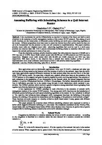
The IIR filter designs differ in the sharpness of the transition between the pass band and stop band, where they exhibit various characteristics. 1. Butterworth filters The frequency response of this filter has no ripples in the passband and the stopband therefore it is called maximally flat filter. Butterworth filter uses a Taylor series approximation to the ideal at both ω=0 and ω=∞.
Fig.6 Response of Butterworth filter We can see from above figure as order of filter increases response of filter closer to the ideal response. Butterworth filters have following characteristics: Smooth response at all frequencies. Monotonic decrease from the specified cut-off frequencies. Maximal flatness, with the ideal response of unity in the pass band and zero in the stop band. 3dB down frequency, that corresponds to the specified cut-off frequencies.
www.iosrjournals.org
30 | Page
A High Performance & Efficiently Designed IIR Filter Using Graphical Virtual Tool (LabVIEW) The transfer function of Butterworth filter is as follows
where n is the order of filter. 2. Chebyshev filters This filter uses a chebyshev approximation across the passband and a Taylor series at ω=∞. Characteristics of this filter is as follows Minimization of peak error in the passband. Equiripple magnitude response in the passband. Monotonically decreasing magnitude response in the stopband. Sharper rolloff than Butterworth filters. Chebyshev filter can achieve sharper transition between passband and stopband with lower order filter than Butterworth filter. This results in smaller absolute errors and faster execution speeds. Frequency response of this filter is given by
where ε is a parameter of the filter related to ripple present in the passband and T N(x) is the Nth order Chebyshev polynomial. TN = cos(N cos-1x) = cos(N cosh-1x)
|x|≤1 |x|≥1
(5)
Fig.7 Response of Chebyshev filter
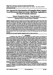
3. Inverse Chebyshev filters Inverse Chebyshev filter uses a Taylor series approximation at ω=0 and a Chebyshev across the stopband. This filter differ from chebyshev filter in following ways These filters minimize peak error in stopband instead of passband. These filters have an equiripple magnitude response in the stopband instead of passband. These filters have a monotonically decreasing magnitude response in the passband instead of stopband. www.iosrjournals.org
31 | Page
A High Performance & Efficiently Designed IIR Filter Using Graphical Virtual Tool (LabVIEW)
Fig.8 Response of Inverse Chebyshev filter 4. Elliptic filters The elliptic function filter uses a Chebyshev approximation across both the passband and stopband. Elliptic filters have following characteristics Minimization of peak error in the passband and the stopband. Equiripples in the passband and stopband Elliptic filters provide the sharpest transition between the passband and stopband, which accounts for their widespread use. Transfer function of Elliptic filters is given by
where UN(x) is the Jacobian elliptic function of order N and ε is a constant related to passband ripple.
Fig.9 Response of Elliptic filter
VIII. SIMULATION AND DISCUSSION IIR filters are used for applications where linear characteristics are not of concern. IIR filter is better for lower order tapping. IIR filters must have at least one pole. It is a recursive filter means it has feedback. IIR filters may be unstable depending on the location of poles where as FIR filter is always stable. Pole-Zero plots is an important tool. It can be used to determine stability. We can distinguish from pole-zero plot whether the filter is low pass, high pass, band pass or band stop. Low pass filters have poles closer to the origin than zeros. They may not have zeros at all. High pass www.iosrjournals.org
32 | Page
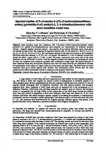
A High Performance & Efficiently Designed IIR Filter Using Graphical Virtual Tool (LabVIEW) filters will have the zeros close the origin and will probably have at least one on the origin. Band pass filters will have zeros close to the origin and some poles farther away. The transfer function of 3rd order elliptic low pass filter is given by
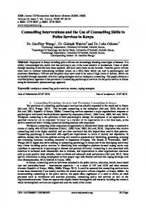
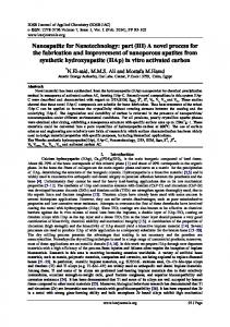
If both poles and zeros of a transfer function are all inside or on the unit circle of the z-plane, the filter is called minimum phase. Frequency responses of different IIR filters are shown in following figures under following parameters Lower cutoff frequency-2K Upper cutoff frequency-3.80K Passband ripple-0.03 Stopband attenuation-90.00
Fig.10 Pole-zero plot of 3rd order Elliptic filter
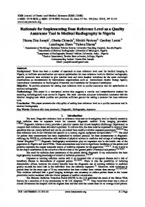
Fig.11 Frequency response of 4th order Butterworth filter
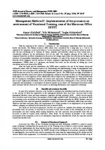
Fig.12 Frequency response of 4th order Chebyshev filter
www.iosrjournals.org
33 | Page
A High Performance & Efficiently Designed IIR Filter Using Graphical Virtual Tool (LabVIEW)
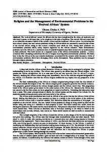
Fig.13 Frequency response of 4th order Inverse Chebyshev filter
Fig.14 Frequency response of 4th order Elliptic filter
Fig.15 Frequency response of 4th order Bessel filter ACKNOWLEDGEMENT The authors are thankful to Mr. Aseem Chauhan (Additional President, RBEF and Chancellor AUR, Jaipur), Maj. General K. K. Ohri (AVSM, Retd.) Pro-VC & Director General, Amity University, Uttar Pradesh Lucknow, Prof. S. T. H. Abidi (Director ASET, Lucknow Campus), Brig. U. K. Chopra (Director AIIT & Dy. Director ASET), Prof O. P. Singh (HOD, Electrical & Electronics) and Prof. N. Ram (Dy. Director ASET) for their motivation, kind cooperation, and suggestions. REFRENCES [1] [2] [3] [4] [5]
Aimin Jiang and Hon Keung Kwan,“IIR Digital Filter Design with Novel Stability Criterion Based on Argument Principle” Department of Electrical and Computer Engineering,University of Windsor , vol. 1, pp. 126-131, 2007 Beyon, J. Y., Hands-On Exercise Manual for LabVIEW Programming, Data Acquisition and Analysis, Prentice Hall, Inc., New Jersey, 2001 Chugani, M. L., LabVIEW Signal Processing, Prentice Hall, Inc., Upper Saddle River, New Jersey, 1998 [4] Clark C. L.,LabVIEW Digital Signal Processing and Digital Communications, Tata McGRAW-HILL, 2005 Fahmy M.F., Abo-Zahhad M. and Shoby M.1., "Design of elective Linear Phase Switched-Capacitor Filters with Equiripple Passband Amplitude Responses", IEEE Trans. On Circuits and Systems, CAS-35, no. 10, pp. 1220-1229, 1988 Jackson L. B., Digital Filters and Signal Processing, 3rd ed., Kluwer Academic Publishers, 1996
www.iosrjournals.org
34 | Page
A High Performance & Efficiently Designed IIR Filter Using Graphical Virtual Tool (LabVIEW) [6] [7] [8] [9] [10] [11] [12] [13] [14] [15] [16] [17] [18] [19] [20]
[21] [22] [23] [24] [25] [26] [27] [28] [29] [30] [31] [32]
[33] [34] [35] [36] [37] [38] [39]
Namjin Kim, “Digital Signal Processing System-Level Design Using LabVIEW”, Elsevier Inc.,vol. 1, 122-127, 2005 Oppenheim, A.V., R.W. Schafer, Discrete Time Signal Processing, 2nd ed., Pearson Education, 2005 Proakis J.G., and D.G. Manolakis, Digital Signal Processing, Principles Algorithms, and Applications, 3rd ed., Pearson Education, Inc., 1996 Wells, L. K. and Travis, J., LabVIEW for Everyone Graphical Programming Made Even Easier, Prentice Hall, Inc., Upper Saddle River, New Jersey, 1997 FDS- Filter design system for SPW, Product data sheet, Comdisco, Inc., 1990. A. H Gray and J. D Markel, “A Computer Program for Designing Digital Elliptic Filters”. IEEE Trans. Acous., Speech Signal Processing vol. ASSP-24, pp.529-538, 1973 A.T. Chottera and G.A. Jullien, “A linear programming approach to recursive filter design with linear phase,” IEEE Trans. Circuits Syst., vol. CAS-29, pp.139-149, 1982 V. Sreeram and P. Agathoklis, “Design of linear phase IIR filters via impulse response graminas,” IEEE Trans. Signal Processing, vol. 40, pp.389-394, 1992 Essik, J., Advanced LabVIEW Labs, Prentice Hall, Inc., Upper Saddle River, New Jersey, 1999 Jackson L.B., Digital filters and signal processing, 3d ed., Kluwer Academic Publishers, 1996 R.C. Eberhart, Kennedy J. A new optimizer using particle swarm theory, Proceedings of the Sixth International Symposium or Micromachine and Human Science, Nagoya, Japan. pp 39-43, 1995 N. Kehtarnavaz and C. Gope, “DSP system design using LABVIEW and SIMULINK: A comparative evaluation”, vol.4 pp. 165-169, 2006 Later Mohammad Abo- Zahhad et.al., filter designer: A complete design and synthesis program for lumped, wave-digital, FIR and IIR filters, 1996 L.R. Rabiner, N.Y.Graham, and H. D. Helms, “Linear programming design of IIR digital filters with arbitrary magnitude function”, IEEE Trans. Acoust., Speech Signal Processing, vol. ASSP-22, pp.117-123, 1974 M.F. Fahmy, M. Abo- Zahhad and M.I. Shoby, “Design of Odd degree Linear Phase Sampled- Data Bandpass Filters with Equiripple Amplitude Response” Inter. J. of Circuit Theory and Applications, vol. 17. pp. 87-101, 1989. M. Abo-Zahhad, Sabah M.A. and M.Yaseen, “Interactive Software Development for the Design and Synthesis of Lattice and Bireciprocal Wave – Digital filters”, Proc. Of the 2nd Inter. Conf. on Engineering Research, ICER-95, Port Said, Egypt, pp. 199-216, 1995 J.H. Mc.Clellan T.W. Parks and L.R. Rabiner, “A Computer Program for Designing Optimum FIR Linear Phase Digital Filters”, IEEE Trans. Audio Electroacoustic, AU-21, pp. 506-526, 1973 Thede Les, Analog and Digital filter design using C, Prentice Hall, Inc., Upper Saddle River, NJ, 1996 M. Abo-Zahhad and T. Henk, “Design of Selective Low pass Sampled-Data and Digital Filters Exhibiting Equiripple Amplitude and Phase Error Characteristics”, Inter. J. of Circuit theory and Applications, vol. 23. pp. 59-74, 1995 W.S. Lu, S.C. Pei, and C.C. Tseng, “A weighted least squares method for the design of stable 1-D and 2-D IIR digital filters”, IEEE Trans. Signal Processing, vol. 48, pp. 1-10, 1998 S. Chen, “Minimum sensitivity IIR filter design using principle component approach”, vol.8 pp. 342-347, 1991 J. Kennedy, R.C. Eberhart, Particle swarm optimization, Processing, Principles Algorithms, and Applications, 3d ed., Pearson Education, Inc., 1996 X. Zhang and Hiroshi Iwakura, “Design of IIR Digital Allpass filters Based on Eigenvalue Problem”, vol.13, pp. 1333-1338, 1999 C.C.T Seng and S.L. Lee, “Minimax design of stable IIR digital filter with prescribed magnitude and phase responses”, IEEE Trans. Circuits Syst. I, vol. 49, pp. 547-551, 2002 D.J. Krusienski, W.K. Jenkins, Particle swarm optimization for adaptive IIR filter structures, Evolutionary Computation, 2004, Congress on vol. 1, pp. 965-970, 2004 Balbir Kumar and Ashwani Kumar, “Design of Efficient FIR filters for the Amplitude Response”, vol. 16, pp. 122-125, 1999 C.C. Tseng, “Design of stable IIR digital filter based on least power error criterion”, IEEE Trans. Circuits Syst., vol. 51, pp. 1879-1888, 2004 Adam Slowik and Michal Bialko, “Design and Optimization of IIR Digital Filters with Non- Standard Characteristics Using Particle Swarm Optimization Algorithm”, Department of Electronics and Computer Science, Technical University of Koszalin, vol. 1, pp. 276282, 2007 A. Slowik, M. Bialko, Evolutionary design of IIR digital filters with non- standard amplitude characteristics, 3rd- National Conference on Electronics, Kolobrzeg, pp. 345-350, 2004 Chia- Nan Chang, Hui- Kang Teng, Jun- Yuan Chen, and Huang- Ten Chiu, Department of Electronic Engineering, National Taiwan University of Science and Technology, “Computerized W.S. Lu and T. Hinamoto, “Optimal design of IIR digital filters with robust stability using conic-quadratic- programming updates”, IEEE Trans. Signal Process., vol. 51, pp. 1581-1592, 2003 S. Chen, R.H. Istepanian and B.L. Luk, Digital IIR filter design using adaptive simulated annealing, Digital Signal Processing, vol. 11, No. 3 pp. 241-251, 2001 W.S. Lu, “Design of stable IIR digital filters with equiripple passbands and peak- constrained least- squares stopbands,” IEEE Trans. Circuits Syst. II, vol. 46, pp. 1421-1426, 1999 W. S. Lu, “Design of stable minimax IIR digital filters using semi definite programming”, Proc. Int. Sym. Circuits and systems, vol. 1, pp. 355-358, 2000 National Instruments Corporation, LabVIEW: Measurements Manual, July 2000
Author’s Bibliography
Ms. Shikha Tiwari, She is completed M.Sc (Electronics) from CSJM University, Kanpur. Currently She is pursuing M.Tech (Electronics and Communication) from Amity University, Lucknow Campus. She has published a paper titled as “A Novice Meta-Materials based Designing of an Highly Efficient Antenna & its Applications: An Overview” in International Journal of Semiconductor Science and Technology. www.iosrjournals.org
35 | Page
A High Performance & Efficiently Designed IIR Filter Using Graphical Virtual Tool (LabVIEW) Mr. Rajinder Tiwari, PhD (P), M.Tech, MIETE is a member of academic staff of Department of Electronics & Electrical Engineering (ASET), Amity University Uttar Pradesh, Lucknow, where he is serving in the capacity of Asstt. Professor in the Department of Electronics Engineering (ASET). He has done M.Tech (I&CE) and M.Sc (Electronics) from NIT, Kurukshetra and University of Jammu, respectively. Presently, he is pursuing Ph.D. (ECE) from Department of Electronics Engineering, Kumaon Engineering College, Dawarahat (Almora) under Uttarakhand Technical University. Mr. Tiwari has given his contribution to the area of Microelectronics (Modeling & Simulation of the Analog CMOS Circuits for ASP Applications), Embedded System Design, Digital System Design and Process Industries Automation and Control System Design (using Graphical Programming Language with dedicated Hardware). He has published several research papers in International/National Journals/Seminar/Conference. He is associated with several technical institutions and bodies as a life member. Before taking the assignment of Amity University, Uttar Pradesh, Lucknow, he had worked in Electronics for Societal Group, CEERI, Pilani, as a Project Scientist and a Multi – National Company as a Sr. Software Engineer (Bridge Instrumentation Division). He is also associated with the successfully implementation of the Hardware and Software for number of projects undertaken by him and in organizing number of International/National Conferences and Seminars. Mr. Amit K Bajpai, completed M.Sc (Electronics) from CSJM University Kanpur. He is also associated as a life time member of Indian Association of Physics Teachers (IAPT). He is working for Science propagation in all over India mainly for rural areas. He is a Senior Resource Person (SRP), SRP group is coordinated by very great Physicist Prof H. C. Verma, Department of Physics, IIT Kanpur. He is also associated with an NGO called Shiksha Soapn, IIT Kanpur. He has attended many more workshops from different places in India as a SRP member; He has visited BITS pilani, CEERI, Pilani, Rajasthan Homi Bhabha Research Center, Mumbai. He organizes workshops related with Physics for teachers as well as students in different states of India. He developed a CD named as “Fun with Physics” with Vigyan Prasar, Noida.
www.iosrjournals.org
36 | Page