For example, active processing within core routers that have to ... Flexible: LARA++ provides a flexible platform for creating network services based on.
LARA++ Design Specification Stefan Schmid Computing Department Lancaster University January 2000 Work in progress report on the next generation active router architecture of Lancaster University
1 Introduction This report presents a snap shot of work in progress regarding the active network research at Lancaster University. Section 2 outlines our main motivations for the work in the area of active networks. Section 3 introduces the active network architecture LARA++ describing the fundamental ideas and the model of the active network architecture. It provides a detailed description of the active node architecture and the safety and security model. Finally, section 4 compares LARA++ with several other active network approaches.
2 Motivation In contrast to end nodes (i.e. user workstations, PCs), current network nodes are vertically integrated and closed systems. Their functionality is restricted to the currently installed software release of the node vendor. Since router and switch vendors usually have the exclusive rights to upgrade or extend device functionality, there is no true competition for network software. The differences in the programming paradigms have created a growing gap between the capabilities of end nodes and intermediate nodes. Whereas today virtually every user workstation and PC has sophisticated multimedia support built-in, it may still take several years until the first interactive multimedia networks become available. On the one hand, there is not much hope that this situation will change in the near future, considering the fact that network device vendors are the least who want this change. Clearly, they enjoy their dominant and untouchable role in the network business. On the other hand, however, telecommunication companies, who are the main customers of network device vendors, might soon demand more flexible devices in order to approximate service deployment times for network services to those of end user services (for example, Web services or user applications). Concluding this, we might frame the main mission statement of active networking: “Software development for network devices and the deployment within the network should become as simple and dynamic as for end-node applications”. By decoupling network services from the underlying hardware and allowing new services to be loaded on demand, active networks will stimulate and accelerate the evolution of novel network technologies than it is possible today.
1
Thus, active networks might expedite the development of innovative network services and network devices in a similar way than the Internet has challenged the exploitation of IP and Web services. Standardization bodies and network vendors do not delay the development and deployment of new services. Examples of current Internet services that still wait to be fully standardized or more common to be incorporated into vendors network devices include multicast, mobility extensions, DiffServ and IntServ/RSVP, as well as the next generation Internet protocol IPv6. Although we have introduced active networks as a new network technology, it can also be noticed as an old idea – just wrapped in a fancy name. Network administrator, for example, already use network configuration tools and protocols (e.g. SMNP), which facilitate the control and management of the growing featurization and functionality of network nodes for quite some time. State-of-the-art network devices provide extensive control and management tools, which effectively provide some form of programming functionality. This shows that the question is not whether programmable network device functionality is useful or not – this has already been proven –, but what are sufficiently sophisticated and flexible architectures for active networks. It is important to note that there is a significant difference between configurable and programmable devices. Configurable devices, as we have today, limit administrators to enable or disable a pre-determined set of options, fully programmable or active network nodes instead enable network users to compose an infinite range of features. Opponents of active networks claim that the trend in networking shows that “intelligent” computation allowing users to control the network better has moved from the core to the edge of the network. Although this cannot be denied, we believe that by increasing the flexibility and functionality within the network, active networks enable the exploitation of even greater control of the network at the edges. Summarizing we can say that active networks open a new “computational” dimension to networking. This may completely change the way we think about networks and inspire totally new network research activities.
3 LARA++ LARA++ continues the preliminary active network research carried out under LARA. Whereas LARA research focused mainly on the design of a scalable “high-performance” active router architecture, the focus of LARA++ lies in the development of a new componentbased active NodeOS. The architecture of LARA++ introduced here is still in a conceptual stage. Refinements and improvements of the conceptual design are expected resulting from the feedback of the implementation phase.
3.1 Objectives The goals of our involvement in active networks and particularly in the development of LARA++ can be summarized as follows: • Design and exploration of component-based NodeOS Our aim is to develop a new active node (i.e. NodeOS and EE), which is implemented mainly based on software components. Component systems are usually very flexible with respect to composition and extensibility, and encourage isolated development of software components. We expect those benefits to have a very positive effect on the evolution of active networks, but further investigation is required. • Achieving a better understanding of the tradeoffs between flexibility, security and performance The challenge in designing an active network architecture is to find the balance for security and flexibility such that performance is best possible. Based on the
2
development and implementation of LARA++, we hope to achieve further insights on these relations. •
Provisioning QoS in an active node Providing QoS in the network relies largely on the support of QoS within every network node. The challenge is to develop an active node that is capable of providing QoS on all levels, namely for the low-level system processing and the active processing. In addition to the problem of guaranteeing QoS on shared network resources (i.e. transmission bandwidth), QoS support within active networks requires also the control of processing resources.
3.2 Model Independent research in the field of active networks has derived different models for an active network. Some active network architectures assume a homogenous active network infrastructure, where all nodes support active packet processing. For example if active capsules are used as a replacement for traditional network packets, every node in the network must support the active processing model in order to deal with the capsules. Examples are ANTS [TW96, WGT98] and PLAN [Hicks98a]. It is not clear, however, if these assumptions are realistic for large scale networks. Workarounds such as IP tunnelling for active capsules would be required during transition. Our model of active networks does not rely on a homogenous network infrastructure. We believe that the transition to active networks would otherwise be incredibly hard and slow. On the one hand, we believe that within current network infrastructures active computation is only feasible in certain places. For example, active processing within core routers that have to forward thousands of packets per second is not practical yet. On the other hand, we encourage the deployment of active networks where beneficial in order to take advantage of the new opportunities as soon as possible. Time will show if the advantages of active networks will lead future network to a homogenous active network infrastructure. The model we use for LARA++ can be seen as an extension to the current Internet technology where active routers interoperate with legacy routers. Special active networks packets are transparently forwarded in a conventional manner by legacy routers. Building LARA++ “on top” of IP does not limit the architecture in any way. IP is simply used as “bootstrapping” protocol for the active network. As a result, we do not have to address all the issues of networking, such as addressing, routing protocols, and so forth. We simple adapt them. In our work, we initially focus on the “programmable switch” approach, which enables network node functionality to be dynamically extended. Network users and/or administrators can explicitly (or out-of-band) distribute active programs, which are then installed as new functional components on active nodes. Successive data packets might then benefit from the extended functionality. On the one hand, the programmable switch approach is much simpler to introduce gradually (i.e. node by node), whereas active capsules rely usually on a homogenous active network infrastructure. On the other hand, the programmable switch approach can be exploit later to build or adopt a lightweight capsule based active network approach on top of the heavyweight programmable active layer.
3.2.1 Design Features The design approach of LARA++ is best described by the following characteristics: Universal: LARA++ minimizes the assumptions regarding the current state of configuration on a node. For example, an application or user that wants to install a new active component on a node needs no knowledge about the other components installed on the node. LARA++ hides the heterogeneity of the node behind simple abstractions.
3
Dynamic: LARA++ supports on-the-fly installation or removal of components without interruption of the services. However, changing active component configuration might have a direct impact on the service composite. For example, if the administrator replaces the multicasting component with a new version that supports reliable multicast, the service characteristics will change. Efficient: LARA++ minimizes the cost of processing during normal operation by migrating expensive processing tasks (for example, user or component authentication) to infrequently called routines or initialisation of active programs where possible. Flexible: LARA++ provides a flexible platform for creating network services based on composition of many small components. We exploit the benefits of component-based architectures, such as modularity, extensibility and reusability, to simplify development and deployment of customized network services. Secure: LARA++ provides sophisticated safety and security mechanisms. The safety model is based on a layered architecture. The top layer provides a safe and yet efficient execution environment for active user code. Security is based on the principles of user authentication, code signing and access control. Flow-based: LARA++ computation is based on a flow-based rather than a control-based model as in conventional systems. The dataflow drives the computation of the “concurrent” communication processes. The data in the packets implicitly define the control flow of the computation. Depending on the matching packet filters, data packets are processed by different active components, as they pass through the node. Flow-based computation is expected to evince as the perfect model for active processing, since the data is the flow of network packets.
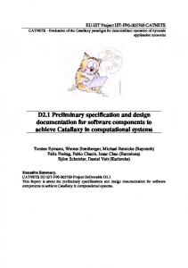
3.3 Architectural Reflection Network communication is usually expressed in terms of the layered abstractions of the OSI Reference Model [ISO84]. The network level provides support for transmission of opaque data packet data between end systems. On those systems, the network layer hides the lowerlevel network complexity (i.e. link layer data protocols and signalling mechanisms, physical transmission of the data, etc.) to the higher-level services. Traditionally, processing above the network level is by definition constrained to end systems as supposed to network devices. Active networking, however, breaks this traditional view since computation performed within an active network can be user- and application specific. In addition, the level on which active computation takes place may vary. Figure 1 illustrates how the active networks architecture for network nodes and end systems can be described in terms of the OSI model. The marked areas (blue) express the layers where active network processing takes place. Although we used the layer terminology defined by the OSI model to express the semantics of data processing on each level, it is important to distinguish the architecture of the protocol stack from the engineering approach of a specific node.
4
Router
End Node
Active Router
Active End Node
Application Layer Presentation Layer Session Layer
layered processing
cut-through processing
Transport Layer Network Layer Link Layer Physical Layer
Figure 1: How active networks fit in the OSI reference model
Conventional implementation of layered protocol suites involves the sequential processing of data units as they pass up and down through the individual layers of the protocol stack in every node. Whereas this approach benefits from the isolation of the functional module for each layer (for example, it simplifies independent implementation of modules), experience has shown that this approach trades off performance. Fast data processing in network architectures demand “cut-through” mechanisms that dispatch data directly to the appropriate modules without having the overhead of passing each layer. In most current end systems the operating system clearly differentiates between the transport and upper-level layers. The user-level socket API (i.e. Berkley sockets or MS Winsock) can be viewed as the upper-level service interface to the transport layer. The exchange of data between those layers is processed by means of expensive copy operations on PDUs. Active network implementation should not be built on top of these user-level interfaces, since performance is vital in active devices. Conclusion: Although the layer model is still valuable from a conceptual point of view for active networks, the implementation of active nodes need to be engineered in a “vertical” fashion, where active processing is limited to one subsystem. In network nodes, the active network subsystem collapses the protocol stack above the link layer into one subsystem. On end systems, the active network subsystem passes the data units to the normal protocol stack after completion of the active processing.
3.4 Active Node A key difficulty in designing active networks is to allow nodes to execute user-defined programs while providing reliable network services for others. An active node must therefore protect co-existing network protocols and services from each other and control the shared resources. LARA++ executes active code only within a restricted environment that limits access to service routines and shared resources. The framework for our safet y and security model is based on a layered architecture, where higher levels are limited and controlled by lower level policies. The active node is assembled out of the following four layers: (i.) The NodeOS provides a set of low-level service routines and system policies to access and manage local resources and system configurations. (ii.) The Execution Environments (EE) form the management unit for resource access and security policies, which are enforced on every active program within the environment. EEs define a set of passive components (or libraries) exported to the active processes running within the EE.
5
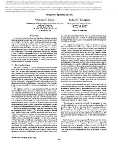
(iii.) The Processing Environments (PE) are the environments for active component processing of trusted components. They provide computational services (i.e. programming interface) for active components. Trust relations among active components are defined upon the code producer and network user who instantiates the component. Active components are exclusively assigned to PEs meaning that an active component can only be executed within the context of exactly one PE. For performance reasons, PEs implement their own user-level thread scheduler that enables exceptionally fast thread scheduling among trusted components. (iv.) The Active Components (AC) hold the active programs. The active code is executed by means of one or several user-level threads. ACs executed within the same PE share the same virtual address space; they must therefore trust each other. Figure 2 shows a graphical illustration of the layered node architecture.
Execution Environment Processing Environment
Active Components
System API
Active NodeOS Figure 2: The layered architecture of LARA++
Unlike other active network architecture, LARA++ introduces the concept of processing environments as an extra layer between the actual active programs and the execution environment. Although it might seem to make the execution of active code more complex and heavyweight, we introduced it for exactly the opposite reason. PEs allow trusted components of an EE to be very efficiently processed in a process-like environment by means of a lightweight thread scheduler and a shared virtual memory address space. It should also be noted that the LARA++ layer architecture is not layering the data handling in the node. Whereas conventional layered systems process data on each level before it is passed on, LARA++ supports cut-through mechanisms that enable very fast data processing, despite multiple layers. Data packets, for example, are memory mapped directly into the address space of the processing environments. Thus, the overhead introduced by these layers occurs mainly during startup of the environments and active programs where expensive security checks need to be performed.
6
3.4.1 Component Architecture The LARA++ architecture is entirely component based. On the one hand, the NodeOS is mainly constituted out of LARA++ components. On the other hand, LARA++ provides a platform for network services development based on the composition of many small components. We believe that this component-based architecture is advantageous over traditional implementations, since network services can be more easily customized to meet the needs of applications. Components within the LARA++ architecture can either be active or passive. Active components, on the one hand, perform the active computations on a node based on one or more execution threads. Passive components, on the other hand, provide merely static functionality, like libraries. Components can also be differentiated regarding their function. User components are those active programs or libraries that are injected by users of the active network. System components, in contrast, are the components that constitute LARA++ and expose the system API to low-level resources and service calls. In order to secure active nodes from fraudulent active programs, execution of user components is bound to the lowprivileged execution environments defined by the PEs. During component installation, components need to register with the node local component directory service. When components are instantiated, they must register themselves with the component registry. The component directory service can be queried to check if the code base for a specific component is available on the local node or if the dynamic loader needs to be invoked to retrieve the code first. The directory service, provided by the active NodeOS, is global to the system. The component registry, in contrast, is managed on two levels. Every PE manages the registration of the components executed within the PE. On the system level, the NodeOS provides a global component registration for the node. The component registries maintain references to the instantiated components. Component references are required for component interaction (i.e. exchange of data and invocation of methods). In order to allow interactions among components, they need to have a standardized interface. LARA++ proposes a similar technique as the IUnknown provided by Microsoft’s COM model to keep the mandatory interface as small as possible. The IUnknown interface allows components to query the interfaces of a component. It is therefore part of the minimal interface besides the interfaces for instantiation and destruction of components, namely ICreate and IDestroy. Inter-component data communication within LARA++ is based on an asynchronous communication model. Figure 3 shows how active components are decoupled by means of a FIFO pipe. The FIFO pipe is managed by the PE, which hosts the receiving component. If both components reside in the same PE, communication is handled by a PE local service routine that queues the incoming data and wakes up the receiving component. Otherwise, a more heavyweight “inter-process” communication mechanisms is required to invoke the service routine in the receiving PE.
Active Component
FIFO Pipe
QoS
Figure 3: FIFO Pipes decouple active components and facilitate asynchronous inter-component communication
On the one hand, LARA++ communication seems to be very similar to the communication model of packet-switched networks. On the other hand, inter-component communication
7
within LARA++ differs with respect to several aspects: (1) LARA++ communication is only based on the exchange of pointers that direct to the memory area where the actual packet data resides. Thus, “network bandwidth” within LARA++ inter-component communication is virtually infinite; and (2) LARA++ components can directly communicate with every other component. Hence, the “component network” is fully connected. The similarity between the LARA++ internal “component network” and real packet-switched networks is remarkable. We therefore believe that it is worthwhile to consider the results of network research and experience in our design. For example, QoS within inter-component communication can be accomplished by means of priority queuing at the receiver. When the receiver reads out the FIFO pipe, it first places the data units in the appropriate priority queues, which are then served depending on their QoS constraints.
3.4.2 Packet Processing Active processing within LARA++ is mainly driven by three key elements: the packet classifier, the classification graph and the packet filters. Upon packet arrival at a LARA++ active node, packets are directly passed to the packet classifier, which then “routes” the packet through the component space. The classifier is responsible that the appropriate active programs are invoked in the correct order. For this purpose, the classifier maintains the classification graph that defines the order upon which active computation is applied on a packet. Packet filters are used to specify the data packets that an active component wants to process. Active components register their filters with the classifier at instantiation time.
3.4.2.1 Classification Hierarchy and Graph The classification hierarchy is the basic structure used to identify the order upon which packet filter should be applied. The hierarchy, for example, defines that the transport protocol should be identified before a filter on a transport protocol port should be applied. Since processing of data, as they pass through the active router architecture, needs to be processed in a certain order, we define the basic structure according to the order defined by the TCP/IP layer model. Figure 4 illustrates the rational behind this.
Active Router Application Support Layer
/aspin
/aspout
Transport Layer
/tspin
/tspout
Network Layer
/netin
/netout
Link Layer Physical Layer
Figure 4: Basic classification hierarchy is defined according to the TCP/IP layer model.
In addition to the ordering imposed by the layer model, the individual protocol stacks (for example, IPv6, TCP, UDP) also need to process their headers, options and so forth according to a certain order, which is usually inherent to the protocol. For example, the extension
8
headers of IPv6 packets must be processed according to the specified order (see also Table 1 below). The general processing order of packets passing the active router, defined by the classification hierarchy, is described in a MIB like fashion – either by means of a textual or numerical representation – as illustrated in the extract printed here: /netin /netin/ip /netin/ip/ipv4 /netin/ip/ipv4/options … /netin/ip/ipv4/flags … /netin/ip/ipv6 /netin/ip/ipv6/options /netin/ip/ipv6/options/hopbyhophdr /netin/ip/ipv6/options/desthdr /netin/ip/ipv6/options/routinghdr … /netin/sbx /tspin /tspin/udp … /tspin/tcp … /aslin … /aslout … /tspout … /netout /netout/ip /netout/ip/ipv4 /netout/ip/ipv4/routing …
1 1.1 1.1.1 1.1.1.1 … 1.1.1.4 … 1.1.2 1.1.2.1 1.1.2.1.1 1.1.2.1.2 1.1.2.1.3 … 1.2 2 2.1 … 2.2 … 3 … 4 … 5 … 6 6.1 6.1.1 6.1.1.1 …
Table 1: A simplified Classification Hierarchy in a MIB-like fashion
The classification graph is managed by the packet classifier as a linked n-nary tree structure. It includes all registered packet filters in the tree structure according to their order defined by the classification hierarchy. Figure 5 shows a simplistic representation of a classification graph, and how the packet classifier manages it.
9
Active Router
/tspout
Transport Layer /tspin options flags flowlabel
desthdr
ipv4
options /netin/ipv6/options/desthdr ipv6 icmp
Network Layer /netin
Figure 5: A simplified classification graph as it is stored and managed by the packet classifier
3.4.2.2 Packet Classifier The packet classifier defines the “route” of a packet through the active component space, as it passes the active node. It “filters” incoming network packets based on the installed filters in the classification graph. The n-nary tree structure is parsed with a left-to-right depth-search approach. If a filter matches a packet, it is “forwarded” to the active component associated with the filter. When the component has completed the active processing, the classifier continues to classify the packet at the point in the classification graph defined by the output channel parameter of the filter (see next section for further information). If no output channel is defined, the classifier continues at the same level (if multiple filters may match) or restarts at the previous level (if filters must match exclusively as, for example, in the case of the transport protocol: either /tspin/udp or /tspin/tcp should match). Otherwise, if no filter on a level matches, the classifier “backtracks” the tree structure trying to find another match. The classification process for a packet finishes, when the classifier runs out of filters branches in the root node. Since packet classification is one of the essential components of the LARA++ active node architecture, it will be implemented as a system component. The fact that the packet classifier requires low-level access permissions, for example to “unblock” active component or PE threads or to write into the memory space of PEs, demands for a low level implementation within the NodeOS. Processing as part of the low level NodeOS is also expected to be beneficial for the system performance.
3.4.2.3 Packet Filter Packet filters are defined by a set of data including at least the following basic structures: Filters: The actual filters are expressed as lists of tuples where each tuple has the form (offset, bit pattern). In order to enhance packet filter specification, semantics on packet structures can be applied when the offset is specified. For example, if the packet control
10
structure1 exports additional information such as references for the transport header or payload, the offset can be defined relative to “known” references or tags. For example, the filter (TRANSPORT_HEADER+TCP_DSTPORT, 80) checks for all TCP packets with destination port 80. Input Channel: It defines at which point in the classification hierarchy the filter should be insert. A filter that intercepts all packets of a stream with a particular transport protocol port, for example, would define the InputChannel to /tspin/tcp/port. Output Channel: The output channel defines the point in the classification graph where the packet classifier should continue the filtering process upon successful matching the filter in the first place. Active Component Reference: The packet filter includes a reference to the instantiated active component where the packet data needs to be sent to upon a filter match. Principal: Information about the network user who installed the packet filter.
3.4.3 Service Composition The component-based architecture of LARA++ aims for a flexible platform for network services. Services are composed out of many lightweight components where every component adds only limited functionality to the overall service. This approach has the following advantages: • Services are implemented based on a “divide and conquer” approach, which eases the component design. • Component development is facilitated, because only “small” programs with limited functionality are to be developed. • Service composition is very flexible. Because of the tidy component interface definition, replacement and extension of individual components is made straightforward. Even dynamic composition is easy to realise. • Composition techniques simplify constitution of customized and adapted services. Network services can by configured to better meet the needs of the applications. Composition within LARA++ is based on a dynamic and public composition method. Services are composed through insertion of packet filters in the classification graph. If the filter matches data packets, user-defined computation implemented as active component is applied. Thus, packet filters are the means for conditional binding of active components. Only if the filter for a binding of components matches, the binding is in force. Since packet filters are inserted during normal operation of the active node, composition changes dynamically. The fact that several network users might be allowed (depending on the local security policy) to install packet filters matching the same data streams makes service composition a public process. Summarizing, the composition method used within LARA++ can be characterized according to the general composition criteria described in [ANCS98]: • Sequence control is based on the dynamically and public extensible classification graph. • Shared data control is implemented as part of the packet classifier. It determines how data packets are routed through the component space and undertakes the sharing of the network data with the respective components. • Binding time is at execution time since the final binding of components depend on the packet data, or in other words, whether a packet filter matches a packet or not.
1
As the packet traverses the active node, a packet control structure is maintained to store relevant management and optimization information.
11
•
Invocation method is prompted by the arrival of an active packet including the code or a reference to the active component.
3.4.4 Processing Environment The processing environment provides the environment required for the execution of trusted active components. This is so far a unique feature of the LARA++ active node architecture. LARA++ makes use of the performance benefits arising from trust relations. Trusted active programs can be executed within the same protection environment (i.e. address space) without creating security holes. The performance boost results from the fact that thread scheduling is remarkably faster since only a lightweight context switch is involved. Trust relations among active components are determined by means of several criteria, but initially limited to code signatures and user authentication. A simple policy could be to trust only those components that have the same code signature. More complex policies could specify a set of signatures that can be trusted which could also be dependent on the user who initiates the installation. Trusted active component, which are either pre-compiled executables or “on-the-fly” compiled programs, are directly loaded into the PE’s address space and then executed by creating one or more active threads. The load process is performed by the “bootstrap” mechanism provided by the PEs. The verification of code signatures and user identities, and the assignment of components to a trusting PE is the responsibility of the NodeOS bootstrapper. Similarly to other active network architectures, where the system API for the NodeOS is provided by the EE, in our architecture the PE provides this functionality. The system API for active programs is constituted of a set of dynamic link libraries that are linked to the PEs. They provide service routines (i.e. CreateThread, Send, Receive, etc.) that are implemented by the PE itself, or low-level system calls (i.e. RegisterFilter, Alloc, Free, etc.), which are passed through the PE to the NodeOS. The core functionality of the system API for active components must be clearly defined and publicly available. The intermediate processing environment on top of the EE has besides the obvious performance boost for active processing within a PE the advantage that the concept of “module thinning” can be applied on a fine-grain basis. Each PE can provide a specially customized system API depending on the trust relation between the trusted components and the local node. Besides providing an execution environment for active components, PEs also manage trusted passive components. Passive components provide additional functionality, like support libraries, for active components. The PEs are responsible for the instantiation and maintenance of passive components.
3.4.5 Execution Environment In traditional active network architectures, the EE provides most of the functionality of the LARA++ processing environments. However, we consider the EE to be a pure management unit for policing. It defines the legitimate scope for security and resource access policies. Thus, in the scope of one EE, the same policy rule base is enforced on all active components, independent on their processing environment. Although the EE is considered to be the management unit for policing, which includes the policy database of the EE, policy enforcement is performed by the NodeOS. Note that the EE is merely a logical layer without a processing component. The following section gives an overview on the different policy rule specifications supported by LARA++. Since a complete definition of all policy specifications would exceed the size of this document, we merely provide a description of the specification. The definition is not complete, but demonstrates how policies are specified. 12
Rather than providing actual policy rules, as they are required for safe and secure active processing, we merely want to demonstrate how the LARA++ policy framework allows users to dynamically define policies.
3.4.5.1 Policy Specification Policy specification is based on several well-known definitions (for example, the system API, resource types) and node-local domains. Domains define collections of objects that are especially grouped for management purposes (i.e. to apply common policies). LARA++ policies make use of several domains in order to keep the specification simple and scalable. These domains include: • Component Group Domain: This domain defines the association between component types (for example components for IPv4 routing, IPv6 option processing, media compression) and component groups. Policy definitions can be greatly simplified through the notion of component groups, for example, system components, trusted components, authenticated components, and user components. Components that have either none or an unknown component type are assigned to the component group: all. • User Group Domain: The user group domain defines user groups and assigns particular users to groups based on their identities. User groups are, for example, administrators, network administrators, privileged users, authenticated users, unauthenticated users, and all users. These groups can then be used within policy definitions to grant or deny access to whole groups of users rather than only individual users. Groups can also consist of only one user. If a network user cannot be authenticated, he/she is assigned to the user group: all. Also, a special user group is the owner group. The reference is useful to describe policies related to the owner of a component or resource. • Code Producer Domain: This domain defines code producers (e.g. Microsoft, Cisco, etc.) and assigns well-known code signatures (or authentication codes), which are verified upon arrival of an active program. Active programs can then be referenced based on their code producer within policy rules. Active programs that have either none or an unknown code signature are assigned to the group of unknown code producer. The LARA++ policy rules can be categorized according to their protection scope, namely for the instantiation of active components, the installation of packet filters and the run-time control of components. 3.4.5.1.1 Instantiation of Active Components Policies rules regarding the instantiation of active components are of one of the following general forms:
(allow|deny) (allow|deny)


Both types are provided to allow node administrators to define policies based on the code producer and the component type. Those rules are evaluated according to a logical OR operation. The following example rules illustrate why both types are useful and how they interrelate: user components cisco


allow allow


network administrators authorized users


Since components from Cisco might be more trusted than code from unknown producers, the second rule softens the constraint of the first rule, namely that only network administrators are able to instantiate user components, by allowing even authorized users to install Cisco’s user components.


13


 Note that the default policy denies instantiation of components from any code producers or of any component group for all users, except to administrators. 3.4.5.1.2 Installation of Packet Filter Policy rules to control the installation of packet filters in the classification graph have the following general form:


[]


(allow|deny)


The inchannel defines where in the classification hierarchy filters can be installed. The optional outchannel specifies where in the hierarchy filtered packets need to be re-insert. If this value is not specified, the inchannel is assumed. The operation defines whether the data can be read [r], copied [c], read/written [rw] or copied/written [cw]. The fact that the classification graph is hierarchically structured is useful in order to grant users access to a whole subtree with only one rule. Therefore, the asterisk [*] is used to express that the whole subtree is addressed. The plus sign [+] is used to indicate that only the present level within the hierarchy is addressed. As in the case of component instantiation, the default policy for filter installation denies any installation except for administrators. A few exemplar policy rules are included to illustrate how these rules can be applied:


rw c rw rw


allow allow allow allow


network administrators authenticated users privileged users sschmid


The first example simply allows network administrators to install read/write packet filters anywhere in the classification hierarchy above the IP level. Since the output channel is not specified, components must return the packet to the same point in the classification graph. The second example allows authenticated users to install a packet filter anywhere above IPv4 in order to copy the data flow. Rule number three enables privileged users to write active components that deal with the option headers of arbitrary IP protocols. The last rule allows the user group sschmid, which most likely consists of only one user, to insert a packet filter for a hypothetical IPv7 protocol. When the active component for the IPv7 protocol has finished, the component must re-inject (or discard) the packets in the stack on the IP level of the output path. 3.4.5.1.3 Run-time Policy Control Policy rules for run-time security and resource access control have one of the two following general forms:


(allow|deny) (allow|deny)


(|) (|)


Both, the system call and the resource tag address well-known entities of a LARA++ node. The former identifies a system call or a group of system calls provided by the NodeOS, whereas the latter addresses a node-local resource such as transmission bandwidth, memory, disk space or processing time. Logical resources (for example, routing table, number of files, etc.) can also be addressed. By default, run-time control policies also deny any system calls and any form of resource access, except for administrators. Since active nodes would then be only usable by administrators, we present a set of example run-time policy rules, which could be used as a “default” configuration: all syscalls disk syscalls disk syscalls bandwidth:100Kbps memory:500KB


allow deny allow allow allow


trusted components all privileged users all all


14


 bandwidth:best-effort processing:best-effort


allow allow


all all


The first rule enables trusted components full access to the system API. The next two rules restrict the access to the system API again by excluding the calls related to disk access. Rule four and five specify the amount of resources “standard” components are allowed to consume. The last two rules define the scheduling algorithm for the network and processing resources.


3.4.6 NodeOS The LARA++ NodeOS enables active components access to node-local resources and lowlevel system services. However, since access to those resources is especially critical regarding safety and security on active network nodes, resource management and system service interfaces must be carefully safeguarded by the policy enforcement component. The following sections describe those components in more detail.


3.4.6.1 Resource Management The design of an active NodeOS must address a range of resource management issues. First, a common model to express a node’s resources is required. Second, control mechanisms for resource sharing are needed. Third, for systems that require guarant eed QoS, reservation mechanisms for local system and network resources need to be considered. And finally, in order to govern the controlled access to resources, secure policies and enforcement mechanisms are required. The latter two issues are still heavily discussed within active network research and thus demand further investigation. In order to reduce the resource management complexity within active nodes, we propose a relatively simple approach based on a small set of platform independent abstractions for the resources of a node: network bandwidth, processing cycles, memory, persistent storage and logical resources. 3.4.6.1.1 Resource Types An active programmer must have an understanding on what the resources are and how they are accessed. Therefore, a common model for active network resources is required. We use the following resource abstractions as basis for active nodes. •


Network Bandwidth Network bandwidth is typically not considered by resource management schemes of conventional operating systems. However, within active network nodes, network bandwidth is clearly a vital resource abstraction. It embodies the units of allocated link bandwidth. It is important to note that within network nodes bandwidth resources are correlated to processing resources. Sending and receiving data from the network requires always some computational resources. In active network nodes, however, this dependency is even stronger since remarkable processing of the dataflow might be involved.


•


Processing Cycles They abstract a node’s processing resources. As long as a node’s processors are not overloaded, it might be sufficient to simple share the resources in a fair manner based on round robin or priority scheduling. However, since computation is likely to be the bottleneck, firm assignments of computational resources depending on processing complexity of packets and throughput requirements might be necessary.


•


Memory Active processing relies heavily on random access memory. However, since memory is in most cases not expected to be a resource bottleneck, resource sharing can be simply controlled through default bounds on memory resources for individual active components.


15


 •


Persistent Storage This resource abstraction encompasses reliable storage (for example, files on disk, or data structure in ROM) for information needed for a longer period. A fixed bound on the number of storage units (i.e. files) and size is expected to be sufficient for resource control.


•


Logical Resources Since active nodes rely on a relatively large number of logical resources of very different types, the development of a uniform mechanism to name those logical resources is suggested. It is already proposed to leverage existing notations, such as those used for SNMP MIBs, where possible [TW96]. We hope to benefit from the existing specifications defined for network nodes.


3.4.6.1.2 Resource Sharing Active nodes must provide mechanisms to limit access to scarce or sensitive resources, because active programmers might not always be aware that some resources are shared. In addition, the system must protect rare resources from imbalanced or fraudulent active components. As a result, LARA++ will employ the following resource control and sharing mechanisms: Scheduling: Resource scheduling is applied to assign resources in a controlled manner. It guarantees that time-multiplexed resources such as bandwidth or computation are shared according to a specified scheduling algorithm. Resource scheduling within LARA++ is used for: • Computation: Threads are the primary abstraction for processing resources. They ar e scheduled according to “fair” (default case), “closest deadline first” or “guaranteed” scheduling algorithms. • Bandwidth: Data packets are the scheduling unit used for transmission resources. Scheduling is accomplished by means of “best-effort” (default case), “priority-based” or “guaranteed” scheduling algorithms. Admission Control: Admission control is commonly used to control resource sharing of spatial-multiplexed resources, such as memory and storage. Resource consume of individual users is restricted by means of accounting and access denial. As consumers make use of resources, the admission control unit accounts the consumed resources to their accounts. If the account limit is full (or empty), further access to the resource is prohibited. Admission control is used for • Memory: Active components will have assigned a maximum memory quantum. Admission control ensures that components do not exceed their limits by accounting memory allocations and denying access when the maximum limits are reached. • Persistent Storage: Similarly as for memory resources, active components will have a maximum limit for persistent storage. 3.4.6.1.3 Resource Reservation Although guaranteed QoS based on resource reservation is often not required, because simple “best-effort” services are sufficient for most applications, recent evolution within Internet research and development indicates that QoS issues cannot simply be ignored. As a result, we design LARA++ such that resource reservation and QoS support is an integral element of the architecture. Thereby we assume that spatial-multiplexed resources, namely memory and persistent storage, and logical resources are not critical with respect to QoS. The bottleneck resources instead are computation and bandwidth. Therefore, we restrict our efforts to develop resource reservation and QoS mechanisms for these resources. The following support is required:


16


 •


The system API must be extended to support system calls that allow active components to make resource reservations through the resource manager. • The resource manger requires admission control support for time-multiplexed resources. A means must be provided for monitoring the resource consume of individual components in order to guarantee that not more than the reserved resources are consumed. • The schedulers and scheduling algorithms of those resource types need to be extended such that they can handle hard deadlines and reserved QoS. The implicit correlation of computational and network resources need to be carefully studied and the impact on QoS support must be investigated. 3.4.6.1.4 Resource Safety The safe manipulation of node resources relies on the following tasks: •


Validation of component or user identities through authentication mechanisms: Before resources are granted, the resource manager must validate the identity of components and users. This is crucial, since resources bounds and reservations are assigned to active components based on their identity or the identity of the user who instantiated the component. Further information on authentication is provided in section 3.5.2.1.


•


Verification of user or component authorization: Before resources can be granted to active components, the resource manager must verify the authorization of the component. Authorization depends on the resource bounds defined by policies and the previously consumed resources. The policy enforcement and admission control components are queried to verify the authorization of users and/or components. For performance reasons, we highly recommend active component developers to write active components such that large bulks of resources are allocated during instantiation time, rather than normal operation time. Otherwise, safety checks for resource allocation will unnecessarily slow down data flow processing on a per packet basis.


3.4.6.2 System API The LARA++ safety and protection model is based on the concept that active code can only be execute within restricted environments. A means for component interaction with the underlying operating system is required in order to achieve any form of inter-component communication. The LARA++ system API exposes the interface for system service routines to active components. It provides the means for active components to access node-local resources and system services. The reminder of this section briefly describes the interface between active components and the NodeOS. The design of the LARA++ system API is guided by the high-level goals presented in the NodeOS interface specification [ANIS99] of the active networking group. The LARA++ system API is implemented as a set of shared or dynamic link libraries. The interface can be divided into several libraries according to their functional support. The link libraries are then dynamically linked with the PEs during instantiation. Trusted active components running within a PE can directly access the interface. Remember that active components operate on “user-level” threads of the PE and share the address space with the PE. Although the system API is extensible, allowing active components to exploit advanced functionality provided by the NodeOS or active router hardware, LARA++ defines a minimal system interface. Any LARA++ active node in order to ensure interoperability and code mobility among active nodes must expose the minimal interface. Research has shown


17


 [WGT98, ANIS99] that a relatively small set of system calls is sufficient to implement such a minimal interface. This is not surprising bearing in mind that active nodes do not intent to provide a general-purpose computational platform, but rather specialise for network communication and data flow processing. During the design phase of the system API, it is important to consider that the set of system calls provided by the active node has a direct impact on the size and execution performance of active programs. Both, program compactness and efficiency are improved if the system API matches the functionality that is required by the program. Due to the limited space, we provide only a brief description of the system API. The following categories of system service routines have been discovered: 3.4.6.2.1 System Environment These system calls allow components to query information related to the local node and the environment. Examples are calls to enquire the node location, local address, link configuration, time and date, and so forth. 3.4.6.2.2 Communication Communication can be differentiated with respect to the communication type: network or inter-component communication. Data packets are either communicated from and to the network or among active components. Active components, however, have no means to access the network directly. Packets are always received first by the packet classifier, before they are dispatched to the active components. As a result, the LARA++ system API for communication can be reduced to support inter-component communication. On the one hand, trusted active components running within the same PE do not rely on interprocess communication mechanisms. Since they share the same virtual address space, a lightweight communication mechanism based on a simple ring buffer in memory can be used to implement the FIFO pipes required for inter-component communication. On the other hand, inter-component communication among components running within different PEs requires a more heavyweight mechanisms such as conventional inter-process communication techniques based on shared memory, COM, LPC, etc. In order to hide the differences of both communication approaches from the active components, who do not know if the receiver component is part of the same PE or not, we propose to implement the system API such that the send service routine decides whether it can manage the transmission internally (in the PE) or if it needs to invoke a inter-process communication mechanism. In addition to the send routine, the system API also requires a receive method to read out the FIFO pipe and a mechanism to register a callback function that handles asynchronous data reception. 3.4.6.2.3 Resource Access Computation The computational resources on a LARA++ node are accessed through system-level threads. The system API provides service routines to create, destroy, start, stop, sleep, block, unblock, and interrupt threads. In addition, functions to create and exploit synchronization methods such as mutual-exclusion locks are required. Since user components are executed within PEs as user-level threads, a high-level thread service must be provided. Consequently, the PEs implement a special user-level thread scheduler and thread API for user components. System components, in contrast, require system support to create and use low-level or systemlevel threads. For example, the PEs need to access the system level thread API in order to implement the user-level thread scheduler. They use a mechanism that dynamically maps user-level threads onto system threads. The system-level thread API provides the same basic functionality as the user-level thread API described above.


18


 Access to the low-level thread interface can be, for example, constrained by means of the following entries in the policy database: systemthreadapi systemthreadapi


deny allow


all system components


Memory Random access memory must be allocated and freed through low-level system service routines, since LARA++ leaves the memory management to the VMM of the node’s operating system. As a result, the LARA++ system related to memory access are directly mapped onto low-level system calls. Policing and accounting is carried out before and after low-level system calls are performed. The LARA++ system API for memory management provides mainly functionality to allocate and free memory. Mechanisms for memory mapping of shared memory are also provided. Persistent Storage Support for file-based long-term storage is required for persistent storage and coarse-grained sharing of data. POSIX-style support for files is provided. System calls such as open, close, read, write, truncate, seek, rename, and mkdir are included. Similar to transient memory access, persistent memory related system calls are also mapped onto low-level operating system calls. Also, accounting and policing is performed in a very similar manner.


3.4.6.3 Policy Enforcement Policy management and enforcement must always be suppressed by components on layers below, since components can not policing themselves if they are not fully trusted. Consequently, the LARA++ architecture leaves the responsibility for policy management and enforcement to the active NodeOS. The NodeOS manages policies on a per-EE basis. This includes maintenance of a policy database for each EE and verification that the policy rule sets are sound at any time. The use of system calls that manipulate shared resources (i.e. allocate, free) or low-level system configurations (i.e. add route) must be strictly controlled. Authentication mechanisms are required to control policies depending on the actual user or component involved. In addition, resource allocation policies demand an admission control component that accounts for resources as they are consumed. Processing time and link bandwidth are allocated by time and data quanta. Respectively, memory resources are allocated by data quanta. Policy control for packet filter installation and component instantiation is less performance critical. The NodeOS must merely intercept the system calls of interest (for example, register filter and create component) and check if they can be processed without violating the policy rule base. Since filter installation and component instantiation are only performed once during component instantiation, as opposed to on a per-packet basis, expensive user authentication and code signatures checks can be carried out as demanded. In contrast, run-time policy control must be highly optimised for performance reasons. Since policy checks are required on a per packet basis (for example, for the send call), it is important to implement lightweight authentication mechanisms. As a result, run-time policing controls system calls and resources access based on the identity of the calling component. Thus, components are the principals who need to authenticate themselves to the policy enforcement. Since this is necessary on a per-packet basis, component authentication needs to be performed efficiently. Therefore, we propose to use unique and random Component IDentifiers (CID) that are assigned to components during


19


 instantiation time. Associated with the CID, the NodeOS creates a Component Data Structure (CDS) that includes all the component specific and run-time critical information. It includes information such as the component group, the user identifier of the user who instantiated the component, the user group, a key bit vector indicating which system calls are accessible, the allocated resources, etc. Run-time policy control can be efficiently enforced because of (a) the fast access to the control structures, and (b) the optimised representation of the control structure for fast policy verification. Upon a system call, the NodeOS employs the CID of the system call as a hash key to “hash” the control structure CDS. Depending on the system call, the NodeOS checks if the service routine is accessible to the component and, in the case of resource allocation, if still sufficient resources are available for the component. If resources are allocated or freed, the resource meters must be updated in the CDS. Security is mainly based on the correctness of the CIDs. They must be sufficiently long such that malicious components cannot easily guess the CID of high privileged system components. In order to defend brute force attacks, the NodeOS destroys active components immediately upon receipt of an invalid CID. In addition, a mechanism is required that prevents impostors from repeatedly instantiate such components. Dynamic change of policies while the active node is operating demands for special consideration for run-time policy enforcement. Since policy checks are not directly performed upon the policy rule base, but upon optimised representation within the CDS, the NodeOS must re-computed the affected CDSs subsequent to a change in the policy database.


3.4.7 Active Code Distribution and Loading Different approaches for active code distribution have evolved. On the on extreme, active packets carry the whole program required for the active processing in-band within every capsule. This of course is only reasonable when very short programs are transmitted. On the other extreme, active programs are pre-loaded into all nodes along the transmission path. This can be done either out-of-band based on a special control protocol, or in-band by means of specially marked data packets. In packet-routed networks, however, the problem with explicit code distribution is to find out which nodes actually require the active program, or what happens, if a route change causes a data flow to pass through routers that do not have the software? In order to resolve the problems originating from dynamic route changes, we propose a mechanism where the data packets include a unique reference to the active component along with initial startup parameters for the component. The frequency for data packets to carry the Active Component Reference (ACR) may vary from once in the first packet, over periodically to always depending on the application. Based on the ACR, the bootstrapper component on active node instantiates the desired active component. If the active component is not known to the system, or in other words was not yet registered with the component directory service, the active node must download the code. Mechanisms are required that enable a node to find and download the missing components from a close source. A solution to the problem of dynamic active code distribution was developed within the ANTS project [WGT98]. A lightweight protocol is used to queries the software from the last hop where the packet originated. Although LARA++ active components might be more heavyweight and rather long-lived compared to the active capsule approach used by ANTS, the problems of code distribution is similar. We therefore suggest the use of a similar approach.


20


 3.5 Safety and Security The LARA++ safety and security framework is based on a combination of known security mechanisms, namely user authentication, code signing and access control, and safe code execution mechanisms. The security model for installation and instantiation of active components, registration of packet filters, and access to low-level system services and resources is primarily based on authorisation. The general principal of this approach is: “who you are determines what you can do”.


3.5.1 Goals The following high-level goals are leading the design of our security mechanisms: • Security should incur minimal costs during normal operations by migrating the cost to an infrequently processed or initialisation phase. • Overall system security should be maximized based on a minimal trusted component base. The former, we achieve by migrating heavyweight public-key authentication of users and active programs to the instantiation phase of the components. In frequently called processing routines (for example, for the data packet processing), we use a very lightweight authentication mechanism based on the component identifier CID (see section 3.4.6.3). The latter, we accomplish by reducing the trusted component base to a public key server and a secure implementation of the low-level NodeOS. Since user and component authentication is based on public key encryption, LARA++ nodes need to trust the public key server providing the public keys. It is the only “remote” entity that needs to be trusted.


3.5.2 Security Mechanisms for Active Code 3.5.2.1 Authentication Although authentication logics are currently mainly used for user identification, we believe, it is also useful to identify mutually suspicious software components that are linked together as in an active network nodes. Consequently, LARA++ employs authentication mechanisms to authenticate active components based on their code signature (if available) besides authentication of the network users who install and instantiate the components. LARA++ users and components must undergo an identity check in order to allow the policy enforcement component to determine authorizations for service and resource access. Authentication within LARA++ is built on public key encryption mechanisms such as RSA or DSA [DSS94]. The “user” encrypts its identity (for example, username) with its private key. Since public key encryption mechanisms ensure (with a sufficient probability) that the encrypted message can only be decrypted with the public key assigned to the user, the receiver of an authentication message can securely verify the user’s identity based on its public key. Thus, secure distribution mechanisms for public keys are required.


3.5.2.2 Code Signatures Code signatures within LARA++ are encrypted checksums of the code base of a software component. They are valuable (1) to identify the code producer of a component based on public key authentication, and (2) to verify that the code has not been modified. LARA++ achieves component authentication and verification of code integrity by comparing the decrypted code signature with the self-computed checksum of a component. Note that the


21


 code signature must first be decrypted with the public key of the code producer before it can be compared. The checksum is derived from a well-known checksum algorithm.


3.5.2.3 Access Control Access control is performed through the policy enforcement component (see section 3.4.6.3). Based on the policy rule base, and the user and component identities, the policy enforcement component checks the authorization for service or resource access. Access control can be divided into the following areas: • Active component execution Instantiation of active components depend on authentication of the network user who wants to instantiate the component and on the code producer. Authorisation policies for component execution can be defined for both, network users and code producers (see section 3.4.5.1). • Network data access Installation of packet filters is also controlled based on the user and component identities. Therefore, policy rules for data access can also be defined for both types of principals. • System API access Access to the system API is again controlled based on user and component authentication. However, since system calls are processed on a per-packet basis (for example, the send call), we introduce a lightweight component “authentication” mechanism, which relies on a unique and random hash key that is generated during component instantiation (see section 3.4.6.3). An interesting starting point for further work in the area of access control policies might be the PolicyMaker system [BFL96]. It provides a special-purpose language for the specification of access control policies in terms of signatures of principals and delegation of trust.


3.5.3 Safe Execution of Active Code Besides the security mechanisms discussed above, the LARA++ architecture provides also safe environments for the execution of active code. The environment includes protection mechanisms for memory and computational resources.


3.5.3.1 Memory Protection Memory protection within LARA++ is achieved based on the concept of Virtual Memory Management (VMM). In general, the safety principles of virtual memory rely on the fact that each process has its own virtual address space. The virtual memory manager ensures that a process has no means to access memory outside its access space. Since context switches between processes with different virtual address spaces are relatively heavyweight2, we exploit the benefits of trust relations among active components such that trusted components can be executed within the same PE. As a result, context switches among trusted components can be performed very efficient. Active components that do not trust each other, however, must be executed within different PEs. An interesting idea, which still requires further investigation, proposes that trust relations among active components could be defined based on the “vote” of currently instantiated components in the trusted environment. Trust policies, such that new components are considered to be trusted as soon as the majority of components agree, could be defined.


2


In the case of a “process” context switch, the virtual address space must be altered and the cached memory pages need to be invalidated.


22


 3.5.3.2 Pre-emptive Thread Scheduling Processing resources are protected from fraudulent or malicious active programs by means of pre-emptive thread scheduling. In order to make sure that threads cannot lock up a processor (or even the whole machine), the scheduler pre-emptively interrupts threads as soon as their scheduling quantum expires. As we have discussed earlier, a range of different scheduling algorithms can be deployed to determine the order of scheduled threads. Examples are: round robin, earliest-deadline-first, priority scheduling. Within LARA++, we propose two types of thread schedulers: System Thread Scheduler: It is responsible to schedule the low-level system threads. Since LARA++ requires a set of system threads (at least one for each PE) to provide processing resources for the PEs, the NodeOS has to control the system thread scheduling. Component Thread Scheduler: The user-level thread schedulers are responsible to schedule the component threads. Thereby, a separate component thread scheduler is used for each PE. Since thread scheduling of trusted components does not demand a heavyweight context switch (because they use the same virtual address space), component scheduling can be very efficiently processed.


4 Related Work The LARA++ active network architecture integrates several technologies: programmable platforms, component-based architectures, and mobile code. Early work in the area of programmable networks has not considered mechanisms that enable users to customize the processing of their data streams in the network. LARA++, however, provides a specialized architecture for customized processing of data streams. The dynamic and public composition model based on packet classification enables network users to apply user-defined computation on data streams. Although a significant part of current research in the area of active networks focuses on the integrated approach where active capsules carry a miniature program in every data packet, we do not discuss how this approach relates to LARA++ in this document. However, we believe that the programmable switch approach should be resolved first in order to provide a flexible active network platform upon which different active capsule approaches can be developed later. The main reason for our approach is that we expect not a single active capsule approach to evolve, which suits all different types of applications. We rather expect that it will be advantageous to develop specialized active capsule programming models for different applications. The flexibility and extensibility provided by LARA++ offers a suitable platform for the development and deployment of different and customized active capsules approaches. Most active network approaches are limited regarding their programming model because safety relies on either specialized scripting languages, for example NetScript [YS96] and NFL [Yem99], which are safe as long as the interpreter is safe, type safe or even proof carrying code. Examples for those active network architectures are SwitchWare [Ale98a] and ANTS [WGT98]. In contrast, LARA++ allows users to distribute active programs either in the form of binary programs or as source code. Just-in-time compilation mechanisms are provided such that source code can be compiled upon arrival at the active nodes. The specially introduced protection layer PE ensures safe execution of active code. LARA++ introduces the concept of trust relations among active components based on the identity of the code producer, which is provided by the code signature. Trusted active components are executed within a single PE that is highly optimised regarding the execution performance of the components. Untrustworthy active code is executed in separate PEs. In other active network approaches, such as ANTS and NetScript, composition is based on the active program or script. The composite is built at execution time. LARA++, in contrast, uses 23


 a dynamic and public composition method that allows any authorised user to dynamically add or remove components to/from the composite. Hence, it is called a public composition method. Composition within LARA++ is a result of one or a series of packet filters matching a packet. The order of active components processed upon a data packet is defined by the classification graph that structures the packet filters in a meaningful order. Since the composite might change on a per-packet basis, the composition method is called to be dynamic. According to the architectural proposal of the AN working group [ANAF98], packet can only be filtered once and must then be fully processed by the associated EE. As a result, in most active network architectures, a node dispatches an incoming packet (or capsule) to the associated EE that processes the packet before it may forward, multicast or discard the packet. The drawback clearly is that a single EE must complete the overall processing of the packet (i.e. IP options, routing, etc.). In contrast, the classification approach or composition model of LARA++ provides more flexibility. It allows active components to gradually add little functionality (for example, a new IPv6 extension header) without having to deal with all the tasks of packet processing. Another related approach is known as the X-Kernel [HP91]. It provides a collection of microprotocols from which protocols can by synthesized. The system achieves high flexibility by composing (i.e. layering) the micro-protocols on a per packet basis. Although the system is capable of expressing a range of protocols, their means of composition is less flexible than that of a programming language. Thus, X-Kernel is classified to be a fully configurable, as opposed to programmable, system. Unlike the active network proposals based on active capsules, such as ANTS and NetScript, LARA++ does not rely on a specialized packet format supported homogenously by every node in the active networks. It is capable of operating with any kind of packets due to the flexible filter-based classification approach. However, in order to program the network device initially, LARA++ makes use of the widespread Internet protocol IPv4 as initial bootstrapping protocol. Afterwards, active nodes can be “actively” programmed to support other bootstrapping protocols. This approach has the important advantage that active networks do not rely on a homogenous network, where every router supports the active protocol.


References [AER] AER. Active Error Recovery (AER). http://www.tascnets.com/panama/AER. [Adl96] A. Adl-Tabatabei et al. Efficient and Language-Independet Mobile Programs. In ACM SIGPLAN conference on Programming Language Design and Implementation (PLDI’96), Philadelphia, PA, 1996. [AFS99] A.W. Appel, E.W. Feltern and Z. Shao. Scaling Proof-Carrying code to Production Compilers and Security Policies. DARPA-funded research project description, January 1999. [Ale97] D.S. Alexander et al. Active Bridging. In Proceedings of SIGCOMM ’97 Conference. ACM Press, 1997. [Ale98a] D.S. Alexander et al. The SwitchWare Active Network Architecture. IEEE Network Special Issue on Active and Controllable Networks, July 1998. [Ale98b] D.S. Alexander et al. The SwitchWare Active Network Implementation. ML Workshop, Baltimore, September1998. [Ale98c] D.S. Alexander et al. A Secure Active Network Environment Architecture. IEEE Network Special Issue on Active and Controllable Networks, 1998 [ANAF98] K. Calvert. Architectural Framework for Active Networks. Active Network Working Group Draft, July 1998. [ANCS98] E. Zegura. Composable Services for Active Networks. Active Network Composable Services Working Group Draft, May 1998. 24


 [ANEP97] D.S. Alexander et al. Active Network Encapsulation Protocol (ANEP). Active Network Working Group Draft, July 1997. [ANIS99] L. Peterson. NodeOS Interface Specification. Active Network Node OS Working Group Draft, July 1999. [ANSA98] S. Murphy. Security Architecture for Active Nets. Active Network Working Group Draft, July 1998. [Bers95] B. Bershad et al. Extensibility, Safety and Performance in the SPIN Operating System. In 15th ACM Symposium on Operating Systems Principles, 1995. [BFL96] M. Blaze, J. Feigenbaum and J. Lacy. Decentralized Trust Management. In Proceedings of the 17th symposium on Security and Privacy, pages 164-173. IEEE computer Society Press, 1996. [Blake98] S. Blake et al. A Framework for Differentiated Services, from IETF Internet-Draft (work in progress), draft-ietf-diffserv-framework-01.txt, October 1998. [Boren94] N. Borenstein. Email with a Mind of its Own: The Safe-Tcl Language for Enabled Mail. In IFIP International Conference, Barcelona, Spain, 1994. [CAML] Caml Home Page. http://pauillac.inria.fr/caml/index-eng.html. [Cardoe99] R. Cardoe, J. Finney, A. Scott, and W.D. Shepherd. LARA: A Prototype System for Supporting High Performance Active Networking. In Proceedings of 1st International Working Conference on Active Networking (IWAN’99), June 1999. [CVP99] T. Chiueh, G. Venkitachalam and P. Pradhan. Integrating Segmentation and Paging Protection for safe, efficient and transparent software extensions. In Proceedings of 17th ACM Symposium on Operating System Principles (SOSP ’99), 34(5):140-153, December 1999. [DES77] Digital Encryption Standard. Technical Report FIPS-46, U.S. Department of Commerce, January 1977. [DH95] S. Deering and R. Hinden. Internet Protocol, Version 6 (IPv6) Specification, RFC 1883, Xerox PARC and Ipsilon Networks, December 1995. [DH98] S. Deering and R. Hinden. Internet Protocol, Version 6 (IPv6) Specification, IETF Internet-Draft (work in progress), draft-ietf-ipngwg-ipv6-spec-v2-02.txt, August 1998. [DOW92] W. Diffie, P.C. van Oorschot and M.J. Wiener. Authentication and Authenticated Key Exchanges. Designs, Codes and Cryptography, 2:107-125, 1992. [DSS94] Digital Signature Standard. Technical Report FIPS-186, U.S. Department of Commerce, May 1994. [EHK96] D.R. Engler, W.C. Hsieh and M.F. Kaashoek. `C: A Language for High-Level, Efficient, and Machine-Independent Dynamic Code Generation. In 23rd Annual ACM Symposium on Principles of Programming Languages (POPL’96). St. Petersburg, FL, 1996. [FMS97] D. Feldmeier, A. McAuley and J. Smith. Protocol boosters. Submitted to IEEE Journal on Selected Areas of Communication, January 1997. [GM95] J. Gosling and H. McGilton. The Java Language Environment: A White Paper. Sun Microsystems, 1995. [Gos95] J. Gosling. Java Intermediate Bytecodes. In SIGPLAN Workshop on Intermediate Representations (IR95). San Francisco, CA, 1995. [Hicks98a] M. Hicks et al. PLAN: A Programming Language for Active Networks. http://www.cis.upenn.edu/~switchware/papers/plan.ps, 1998. [Hicks98b] M. Hicks et al. PLANet: An Active Network Testbed. http://www.cis.upenn.edu/~switchware/papers/planet.ps, 1998. [HP91] N.C. Hutchinson and L.L. Peterson. The x-Kernel: An architecture for Implementing Network Protocols. IEEE Transactions on Software Engineering, 17(1):64-76, January 1991. 25


 [ISO84] ISO. Information Processing Systems – Open System Interconnection – Basic Reference Model. ISO, 1984 [JY97] T. Lindholm and F. Yellin. The Java Virtual Machine Specification. Addison-Wesley, 1997. [LGT98] L. Lehman, S. Garland and D. Tennenhouse. Active Reliable Multicast. In Proceedings of INFOCOM ’98, 1998. [Meru00] S. Merugu et al. Bowman: A Node OS for Active Networks. Submitted to IEEE Infocom 2000. [MHSC99] L. Mathy and D. Hutchison and S. Schmid and G. Coulson. Improving RSVP for Better Support of Internet Multimedia Communications, from ICMCS ’99, Florence, Italy, June 1999. [MHSS99] L. Mathy and D. Hutchison and S. Schmid and S. Simpson. REDO RSVP: Efficient Signalling for Multimedia in the Internet, from IDMS ’99, Toulouse, France, October 1999. [Nec97] G. Necula. Proof-carrying code. In Twenty-Fourth Annual ACM Symposium on Principles of Programming Lanuages, New York, January 1997. [Nec98] G. Necula. Compiling with Proofs. PhD thesis, School of Computer Science, Carnegie Mellon University, Pittsburgh, PA, September 1998. [NL96] G. Necula and P. Lee. Safe Kernel Extensions Without Run-Time Checking. In Second Symposium on Operating System Design and Implementation (OSDI’96), Seattle, WA, 1996. [NL97] G. Necula and P. Lee. Efficient representation and validation of logical proofs. Technical Report CMU-CS-97, School of Computer Science, Carnegie Mellon University, Pittsburgh, PA, January 1997. [Part95] C. Partridge. Using the Flow Label Field in IPv6, RFC 1809, NRL, June 1995. [PS98] P. Pan and H. Schulzrinne. YESSIR: A simple reservation mechanism for the Internet, In Proceedings International Workshop on Network and Operating System Support for Digital Audio and Video (NOSSDAV), July 1998. [RFC1633] R. Braden et al. Integrated Services in the Internet Architecture: an Overview, RFC 1633, June 1994. [RFC1889] H. Schulzrinne et al. RTP: A Transport Protocol for Real-Time Applications, RFC 1889, January 1996. [RFC2205] R. Braden et al. Resource ReSerVation Protocol (RSVP) - Ver 1 Functional Specification, RFC 2205, 1997. [RFC2210] J. Wroclawski. The Use of RSVP with IETF Integrated Services, RFC 2210, MIT LCS, September 1997. [RFC2326] H. Schulzrinne et al. Real Time Streaming Protocol (RTSP), RFC 2326, April 1998. [SA98] Z. Shao and A.W. Appel. A type-based compiler for Standard ML. In Proceedings of ACM SIGPLAN ’95, Conference on Programming Language Design and Implementation, pages 116-129, ACM Press, New York, 1995. [Schmid98a] S. Schmid et al. RSVP Extensions for Flow Labels, from IETF Internet-Draft (work in progress), draft-schmid-rsvp-fl-01.txt, August 1998. [Schmid98b] S. Schmid et al. QoS-based real-time audio streaming in IPv6 networks, from in Proc. of SPIE. 3529, Internet Routing and Quality of Service, November 1998. [Schmid99a] S. Schmid. QoS based Real-Time Audio Streaming on the Internet, “Diplomarbeit” (master thesis) for “Diplom Informatik” (MSc in Computer Science) degree, University of Ulm, Germany, April 1999.


26


 [Schmid99b] S. Schmid. PhD Progress Report. June 1999. [Schmid99c] S. Schmid. A Hop-by-Hop Aggregation Mechanism. Draft Report, August 1999. [Sha98] Z. Shao. Typed cross-module compilation. In Proceedings of ACM SIGPLAN, International Conference on Functional Programming (ICFP’98), pages 141-152, ACM Press, September 1998. [SHS95] Secure Hash Standard. Technical Report FIPS-180-1, U.S. Department of Commerce, April 1995. Also known as: 59 Fed Reg 35317 (1994). [Sil98] S. da Silva. NetScript Tutorial. Version 0.10, October 1998. [SMARTS94] SMARTS. SMARTS Operational Server Manual. System Management Arts, 1994. [Tar96] D. Tarditi et al. TIL: A type-directed optimised compiler for ML. In Proceedings of ACM SIGPLAN ’96, Conference on Programming Language Design and Implementation, pages 181-192, ACM Press, 1996. [Tenn97] D.L. Tennenhouse et al. A Survey of Active Network Research. IEEE Communications, January 1997. [TW96] D.L. Tennenhouse and D.J. Wetherall. Towards an Active Network Architecture. CCR, April 1996. [Van97] V.C. Van. A Defense Against Address Spoofing Using Active Networks. M.Eng Thesis, Massachusetts Institute of Technology, June 1997. [Weth99] D. Wetherall. Active network vision and reality: lessons from a capsule-based system. ACM, SOSP-17, December 1999. [WGT98] D.UJ. Wetherall, J.V. Guttag and D.L. Tennenhouse. ANTS: A Toolkit for Building and Dynamically Deploying Network Protocols. IEEE OPENARCH’98, San Francisco, CA, April 1998 [Yem99] Yemini et al. The Network Flow Language: A Mark-based Approach to Active Networks. Technical Report, Columbia University Computer Science Department, submitted, July 1999. [YS96] Y. Yemini and S. da Silva. Towards Programmable Networks. IFIP/IEEE Internation Workshop on Distributed Systems: Operations and Management, L’Aquila, Italy, October 1996. [ZF83] J. Zander and R. Forchheimer. SOFTNET – An approach to high level packet communication. In Proc. of AMRAD Conference, San Francisco, CA, 1983. [Zhang93] L. Zhang et al. RSVP: A new Resource ReSerVation Protocol, from IEEE Networks. 7, No. 5, September 1993.


27