Hindawi Publishing Corporation Mathematical Problems in Engineering Volume 2016, Article ID 4126123, 8 pages http://dx.doi.org/10.1155/2016/4126123
Research Article Large-Scale Computations of Flow around Two Cylinders by a Domain Decomposition Method Hongkun Zhu,1 Qinghe Yao,1 and Hiroshi Kanayama2 1
School of Engineering, Sun Yat-sen University, Guangzhou 510275, China Department of Mathematical and Physical Sciences, Japan Women’s University, Tokyo 112-8681, Japan
2
Correspondence should be addressed to Qinghe Yao;
[email protected] Received 25 September 2015; Revised 31 December 2015; Accepted 28 February 2016 Academic Editor: Uchechukwu E. Vincent Copyright © 2016 Hongkun Zhu et al. This is an open access article distributed under the Creative Commons Attribution License, which permits unrestricted use, distribution, and reproduction in any medium, provided the original work is properly cited. A parallel computation is applied to study the flow past a pair of cylinders in tandem at Reynolds numbers of 1000 by Domain Decomposition Method. The computations were carried out for different sets of arrangements at large scale. The modeling by domain decomposition was validated by comparing available well-recognized results. Two cylinders with different diameters were further investigated; for different diameter ratios, the wake width ratio and some properties of the critical space ratio that dominates the flow regime were discovered. This result has important implications on future industrial application efforts as well as codes and standards related to the two-cylinder structure.
1. Introduction Cylinder is one of the most common structures in engineering, such as piers and chimney, the struts of offshore platform, the pipe of condenser, and more. When fluid flows through the cylinders, the shedding vortex may cause interference effect. This effect may lead to the vibration of the cylinder structures or fatigue of the materials and as a result, the structure may be destroyed. Due to its importance in engineering applications, flow past two cylinders has been studied by experimental and numerical investigations for several decades [1]. As early as 1977, Zdravkovich classified the characteristic of flow past two cylinders in tandem into three regimes at low Reynolds number (Re). For more complicated applications, Wu et al. [2] studied two cylinders in tandem with wind tunnel and water tunnel at the Re of 1000. The flow visualization in the water tunnel showed the existence of streamwise vortices in spanwise direction. To make out the relationship between different arrangements of two cylinders and Re, Mittal et al. [3] studied incompressible flows past two cylinders in tandem and staggered arrangements (Re = 100 and Re = 1000) by a stabilized finite element method (FEM). Jester and Kallinderis [4] investigated the incompressible flow about fixed cylinder pairs numerically and cylinder arrangements include tandem, side-by-side, and staggered
at Reynolds numbers of 80 and 1000. Hysteresis effects and bistable biased gap flow in tandem arrangements were reproduced. Different combinations of Re and arrangements of cylinders have been reported by many [5–7], as is reported in [8–17] and summarized by Sumner [1]; most of the early researches on this problem contribute to the flow structures induced by different spacing ratios (𝐿/𝐷), Re and variant cylinder shapes. Recently, there has been a lot of interest on the diameter ratio (𝑑/𝐷) of two cylinders in tandem. Zhao et al. studied turbulent flow past two cylinders with different diameters numerically. The hydrodynamic force and vortex shedding characteristics were proved to depend on the relative position of small cylinders around the main cylinder [18]. Mahbub Alam and Zhou investigated the Strouhal number, hydrodynamic forces and flow structures, and vortex shedding frequency of flow past two cylinders in tandem with different diameters in wind tunnel [19]. The diameter of upstream cylinder varied from 0.24 to 1 of the downstream cylinder diameter and the distance between two cylinders remains 5.5 times of the diameter of the upstream cylinder. DingYong et al. conducted the simulation of different spacing ratios and different diameter ratios at Re = 200 using Fluent [20]. Besides two cylinders, Zhang et al. determined the influence of the diameter ratio on the flow past three
2
Mathematical Problems in Engineering
cylinders in two dimensions by applied finite element method [21]. As far as we know, the flow structure of two cylinders in tandem affected by the changing of diameter ratio and spacing ratio is still uncertain, and the computation scale of numerical experiments published research is very limited. To investigate the flow regime more concretely and more subtly, large-scale simulations by Domain Decomposition Method (DDM), which is considered to have better accuracy and less time cost when comparing with conventional methods, are implemented [22, 23]. The large-scale modeling was validated by comparing with others’ reports for two cylinders of the same diameter with different spacing ratios. Moreover, to study its influence to the flow past two cylinders in tandem more comprehensively, the flow structures at specified diameter ratios (𝑑/𝐷 = 0.5 and 𝑑/𝐷 = 1) with different spacing ratios (𝐿/𝐷: 3–6) are investigated. The critical spacing ratio that affects the flow regime is expected to be determined for different diameter ratios. This paper is organized as follows: Section 2 introduces the governing equations to be solved as well as the domain decomposition method (DDM). In Section 3, the models and the boundary conditions are described in detail. Numerical results for different spacing ratio and different diameter ratios (𝑑/𝐷 = 1 and 𝑑/𝐷 = 0.5) are present and compared with others’ work in Section 4. At last, Section 5 draws the conclusions of this work.
2. Formulations 2.1. Governing Equations. Let 𝜕Ω be the boundary of a threedimensional polyhedral domain Ω. 𝐻1 (Ω) is the first order Sobolev space and 𝐿2 (Ω) is the space of 2nd power summable functions on Ω. Under the assumption that the flow field is incompressible, viscous, and laminar, the solving of the model can be summarized as finding (𝑢, 𝑝) ∈ 𝐻1 (Ω)3 × 𝐿2 (Ω) such that for any 𝑡 ∈ (0, 𝑇), the following set of equations hold [24]: 𝜕𝑡 𝑢 + (𝑢 ⋅ ∇) 𝑢 −
1 1 ∇ ⋅ 𝜎 (𝑢, 𝑝) = 𝑓, 𝜌 𝜌 (1)
∇ ⋅ 𝑢 = 0, in Ω × (0, 𝑇) ,
where 𝑢 is the velocity [m/s]; 𝑝 is the pressure [Pa]; 𝜌 is the density (const.) [kg/m3 ]; 𝑓 is the body force [N/m3 ]; 𝜎(𝑢, 𝑝) is the stress tensor [N/m2 ] defined by 𝜎𝑖𝑗 (𝑢, 𝑝) ≡ −𝑝𝛿𝑖𝑗 + 2𝜇𝐷𝑖𝑗 (𝑢) , 𝐷𝑖𝑗 (𝑢) ≡
u(X, t)
X(tn−1 ) ≈ X1 (un−1 , Δt)
X(tn ) = x
Figure 1: A characteristic finite element scheme.
and Neumann boundary conditions 3
∑𝜎𝑖𝑗 𝑛𝑗 = 0
on 𝜕Ω \ Γ × (0, 𝑇)
(4)
𝑗=0
are also applied, where Γ ⊂ 𝜕Ω and 𝑛 is the outward normal direction to 𝜕Ω. 2.2. Characteristic Finite Element Scheme. Using the definition 𝑡𝑛 ≡ 𝑛Δ𝑡, 𝑁𝑇 ≡ [
(5)
𝑇 ], Δ𝑡
a characteristic finite element scheme approximates the material derivative in (1) at 𝑡𝑛 as follows: [23] 𝜕𝑡 𝑢 + (𝑢 ⋅ ∇) 𝑢 ≈
𝑢𝑛 − 𝑢𝑛−1 (𝑋1 (𝑢𝑛−1 , Δ𝑡)) Δ𝑡
,
(6)
where 𝑋1 (⋅, ⋅) is a position function; see Figure 1. Let Iℎ ≡ {𝐾} denote a triangulation of Ω consisting of tetrahedral elements and the subscript ℎ denotes the representative length of the triangulation. The finite element spaces are defined as follows: 𝑋ℎ ≡ {Vℎ ∈ 𝐶0 (Ω)3 ; Vℎ 𝐾 ∈ 𝑃1 (𝐾)3 , ∀𝐾 ∈ Iℎ } , 𝑀ℎ ≡ {𝑞ℎ ∈ 𝐶0 (Ω) ; 𝑞ℎ 𝐾 ∈ 𝑃1 (𝐾) , ∀𝐾 ∈ Iℎ } , ̂ (𝑃) , ∀𝑃 ∈ Γ} , 𝑉ℎ (̂ 𝑢) ≡ {Vℎ ∈ 𝑋ℎ ; Vℎ (𝑃) = 𝑢
(7)
𝑉ℎ ≡ 𝑉ℎ (0) , 𝑄ℎ = 𝑀ℎ ,
1 𝜕𝑢𝑖 𝜕𝑢𝑗 + ), ( 2 𝜕𝑥𝑗 𝜕𝑥𝑖
(2) 𝑖, 𝑗 = 1, 2, 3,
with the Kronecker delta 𝛿𝑖𝑗 and the viscosity 𝜇 [kg/(m⋅s)]. An initial velocity 𝑢0 is applied in Ω at 𝑡 = 0. Dirichlet boundary conditions ̂ 𝑢=𝑢
R3
on Γ × (0, 𝑇)
(3)
where the 𝐶0 (Ω)3 in (7) denotes the continuous function on Ω in three dimensions. 𝑃1 (𝐾)3 denotes the first order polynomial defined by 𝐾 in three dimensions. Note that piecewise linear interpolations are employed for velocity and pressure (see (7) and Figure 2), which does not provide a sufficient condition to link the velocity and pressure space; therefore, the so-called inf-sup condition [25] should be satisfied. In previous work [26], a penalty Galerkin least-squares (GLS) stabilization method for pressure [27]
Mathematical Problems in Engineering
3
0 5D +
+
d
D
11D
U∞ = 0.6 m/s
L
26D x3
x1
Figure 3: Two cylinders in tandem. 3
1
A weak coupling of finite element scheme in (8) is applied and the element searching algorithm for LagrangeGalerkin method only needs to be implemented once in each nonsteady loop [23].
2 Velocity Pressure
Figure 2: A tetrahedron element.
was employed and it was found difficult to be applied for the simulation of complex flows; especially when the flow is very turbulent, the scheme becomes easy to diverge. A stabilization technique for the saddle point problem is employed and the finite element scheme for (1) read as follows [22]. 𝑁𝑇 such that Find {(𝑢ℎ𝑛 , 𝑝ℎ𝑛 ) ∈ 𝑉ℎ (𝑔) × 𝑄ℎ }𝑛=1 (
𝑢ℎ𝑛 − 𝑢ℎ𝑛−1 (𝑋1 (𝑢ℎ𝑛−1 , Δ𝑡)) Δ𝑡
, Vℎ ) + 𝑎 (𝑢ℎ𝑛 , Vℎ )
+ 𝑏 (Vℎ , 𝑝ℎ𝑛 ) + 𝑏 (𝑢ℎ𝑛 , 𝑞ℎ ) +
1 ∑ 𝜏 (∇𝑝ℎ𝑛 , −∇𝑞ℎ )𝐾 𝜌2 𝐾∈I 𝐾
(8)
ℎ
=
1 1 (𝑓, Vℎ ) + 2 ∑ 𝜏𝐾 (𝑓, −∇𝑞ℎ )𝐾 . 𝜌 𝜌 𝐾∈I ℎ
Let (⋅, ⋅) defines the 𝐿 2 inner product; the continuous bilinear forms 𝑎 and 𝑏 in (8) are introduced by 𝑎 (𝑢, V) ≡
2𝜇 (𝐷 (𝑢) , 𝐷 (V)) , 𝜌
𝑏 (V, 𝑞) ≡ −
1 (∇ ⋅ V, 𝑞) , 𝜌2
(9) (10)
respectively. The following stabilization parameter is employed: 𝜏𝐾 = min {
𝜌ℎ𝑘2 ℎ𝐾 Δ𝑡 , , 𝑛−1 }, 2 2 𝑢ℎ ∞ 24𝜇
(11)
where ℎ𝐾 denotes the maximum diameter of an element 𝐾 and ‖ ⋅ ‖∞ is the maximum norm.
2.3. Domain Decomposition Method. The calculating area is a cuboid. The left side of the model is the entrance and the right side is the free outlet. The inlet is placed 5𝐷 to the upstream cylinder and total length is 26𝐷. The nonslip boundaries are placed 5.5𝐷 above and below the cylinders. The height is 4𝐷; see Figure 3 for a two-dimensional projection of the threedimensional model. In order to investigate the relationship between them by large-scale simulation, a parallel computation by DDM [22, 23, 28, 29], which is considered to have better accuracy and less time cost, is implemented in this work. In the domain decomposition system, the whole computation domain is split into 𝑁 nonoverlapping parts, where 𝑁 is the number of threads; in each smaller part, an FEM process is preceded. For the comparison of efficiency of DDM and FEM, please see [23]. A Linux cluster (Intel Xeon
[email protected] GHz × 44, LV RDIMM 12 GB@1333 MHz × 44) in Sun Yat-sen University was used for this computation. For each computation model, 176 threads were created, as can be seen in Figure 4. For each computational model, nonsteady time step is set to 0.01 s and the number of total simulation time is 10 s. The maximum number of Degrees Of Freedom (DOF) is up to 16.6 million and it takes the cluster about 5.8 hours. Details of the computations for each model can be found in Table 1.
3. Modeling and Boundary Conditions Air is assumed to be the fluid in this work. 𝐿 is the distance between the two centers of the cylinders. The diameter of upstream cylinder is d and the diameter of downstream cylinder is 𝐷 (𝐷 = 0.025 m). The time step is 0.01 s and total computation time for each model is 10 s. The kinematic viscosity of the fluid is 0.000015 m2 /s at constant temperature and Re = 1000. The velocity of the coming flow is 0.6 m/s. The air flows into the model with a constant horizontal velocity from the left to the right. The vertical velocity is prescribed to zero.
4
Mathematical Problems in Engineering Table 1: Computation information.
Name Model 1–1 Model 1–2 Model 1–3 Model 1–4 Model 2–1 Model 2–2 Model 2–3 Model 2–4 Model 2–5 Model 2–6 Model 2–7 Model 2–8
Spacing ratio (𝐿/𝐷)
Diameter ratio (𝑑/𝐷)
Number of elements
Number of DOF
Nonsteady loops
Computation time (h)
2 2.15 2.5 3 3 3 4 4 5 5 6 6
1 1 1 1 0.5 1 0.5 1 0.5 1 0.5 1
9,420,393 9,466,412 9,566,559 9,710,157 6,908,469 9,710,157 10,146,357 9,997,736 10,428,101 10,283,886 10,715,636 10,565,696
14,130,590 14,211,123 14,390,891 14,649,874 9,309,739 14,855,135 15,654,964 15,312,582 16,114,294 15,785,861 16,597,006 16,259,744
1000 1000 1000 1000 1000 1000 1000 1000 1000 1000 1000 1000
5.15 5.00 4.35 4.85 3.10 4.68 5.32 4.74 4.97 5.45 5.75 5.53
x3
x2 x1
Figure 4: The domain decomposition of a model: the 176 parts and local details.
The model of two cylinders in tandem with different diameter is shown in Figure 5. The diameter of the upstream cylinder decreases to 0.5𝐷. The diameter of the downstream cylinder remains the same; 𝑑/𝐷 is 0.5.
4. Result and Discussion This section presents the results of numerical simulations for two cylinders in tandem with different spacing ratios (𝐿/𝐷) and diameter ratios (𝑑/𝐷). To confirm the results, the visualization of computational results was conducted and it showed the details of flow field. Micro AVS by CYBERNET SYSTEMS was used to plot Figures 5–14. 4.1. Validation. In order to validate the current modeling, numerical results of two cylinders of the same diameter with different spacing ratios (𝐿/𝐷) were compared to wellrecognized results. Figures 6 and 7 show the comparison of current results with the numerical results reported by Jester and Kallinderis [4]. As is shown in Figure 6, there is a recirculation between the two cylinders at 𝐿/𝐷 = 2. The vortex shedding occurs only behind the downstream cylinder. At 𝐿/𝐷 = 2.15, both reattachment and two vortex streets occur between two cylinder, which presents a bistable
state [4]. When reattachment occurs, the vortices shed from the upstream cylinder fluctuate and reattach to the downstream cylinder; see Figure 7. Recirculation is observed between the two cylinders and vortex shedding is observed behind the downstream cylinder all the time at steady state. At 𝐿/𝐷 = 2.5, the vortex shedding occurs behind both upstream and downstream cylinders, as is shown in Figure 8. The vortex sheds from the upstream cylinder sharply and impinges to the downstream cylinder. The computational results are also validated by comparing with the experiment conducted by Wu et al. [2], and the comparison of the vortex contour is shown in Figure 9. As can be seen from Figure 9, the numerical and experimental results agree with each other very well: the vortices separate from the upstream cylinder reattach to the downstream cylinder. The vortex shedding occurs only after the downstream cylinder. There is no independent vortex street between two cylinders. The computational results present the same characteristic and tendency with recognized results of other researchers. The characteristics of the flow and the vortex shedding are both performed as expected. The numerical experiments also convinced us that the parallel computation with Domain Decomposition Method has good accuracy and efficiency in large-scale simulation, which encouraged us to move forward to investigate the effect of the diameter ratio.
Mathematical Problems in Engineering
5
x2 x3
x2 x3
x1
x1
(a)
(b)
Figure 5: Two cylinders in tandem with different diameter ratios. ((a) 𝑑/𝐷 = 1; (b) 𝑑/𝐷 = 0.5).
(a)
(b)
Figure 6: Streamlines of Model 1–1 at 𝑡 = 8.00 s. ((a) Current results; (b) Jester and Kallinderis).
(a)
(b)
Figure 7: Streamlines of Model 1–2 at 𝑡 = 6.40 s. ((a) Current results; (b) Jester and Kallinderis).
(a)
(b)
Figure 8: Streamlines of Model 1–3 at 𝑡 = 8.00 s. ((a) Current results; (b) Jester and Kallinderis).
4.40 s
(a)
(b)
Figure 9: Contour of Model 1–1 at 𝑡 = 4.40 s. ((a) Current results; (b) Wu et al.).
6
Mathematical Problems in Engineering
10.00 s
(a)
10.00 s
10.00 s
(a)
10.00 s
(b)
Figure 10: Contour at 𝐿/𝐷 = 3, 𝑡 = 10.00 s. ((a) Model 2–1; (b) Model 2–2).
4.2. The Effect of Diameter Ratio. According to the research conducted by Ding-Yong et al. [20], the diameter ratio has strong effects on the characteristic of flow field around two cylinders in tandem. In the research, the downstream cylinder had smaller diameter than the upstream one. With the increasing of the diameter ratio (𝑑/𝐷), the critical spacing ratio increases. Mahbub Alam and Zhou also investigated flow past two cylinders in tandem with different diameters experimentally in wind tunnel [19]. The diameter of upstream cylinder varied from 0.24 to 1 of the downstream cylinder diameter. However, the spacing ratio kept 5.5 times of upstream cylinder diameter. To determine the influence of the diameter ratio (𝑑/𝐷) to the flow field more comprehensively, this paper conducted the study by decreasing the diameter of the upstream cylinder to half of the downstream cylinder. The space between two cylinders remains the same as the corresponding simulation at 𝑑/𝐷 = 1. The visualization of the flow field shows the characteristic between the gap and vortices street. In all arrangements, the vortex shedding occurs behind both upstream and downstream cylinders. However, the volume of the vortices and the complexity of wake flow are different. As can be seen from Figure 10, at 𝐿/𝐷 = 3, the vortices are smaller and but the wake behind downstream cylinder is wider at 𝑑/𝐷 = 0.5 compared with 𝑑/𝐷 = 1. With 𝑑/𝐷 = 1, the vortices shed from the upstream cylinder sharply and impinged to the downstream cylinder. At 𝑑/𝐷 = 0.5, the interference on the upstream cylinder is less than that at 𝑑/𝐷 = 1. In Figure 11, at 𝐿/𝐷 = 4, the vortices are smaller at 𝑑/𝐷 = 0.5 compared with 𝑑/𝐷 = 1. The wake behind the downstream cylinder shares about the same area for 𝑑/𝐷 = 0.5 and 𝑑/𝐷 = 1. The interference on the upstream cylinder is smaller at 𝑑/𝐷 = 0.5 than that at 𝑑/𝐷 = 1. At 𝐿/𝐷 = 5, the vortices and wake behind the downstream cylinder appears smaller and narrower at 𝑑/𝐷 = 0.5 compared with 𝑑/𝐷 = 1. The interference on the upstream cylinder is much smaller at 𝑑/𝐷 = 0.5 than that at 𝑑/𝐷 = 1; see Figure 12. At 𝐿/𝐷 = 6, the vortices and wake behind the downstream cylinder are much smaller and narrower at 𝑑/𝐷 = 0.5 compared with 𝑑/𝐷 = 1. The interference on the upstream cylinder is negligible at 𝑑/𝐷 = 0.5 than that at 𝑑/𝐷 = 1; see Figure 13.
(b)
Figure 11: Contour at 𝐿/𝐷 = 4, 𝑡 = 10.00 s. ((a) Model 2–3; (b) Model 2–4).
10.00 s
(a)
10.00 s
(b)
Figure 12: Contour at 𝐿/𝐷 = 5, 𝑡 = 10.00 s. ((a) Model 2–5; (b) Model 2–6).
Overall, the wake after the downstream cylinder at 𝑑/𝐷 = 0.5 is clearer than that at 𝑑/𝐷 = 1. The vortices that shed from the smaller upstream cylinder impinge to the downstream cylinder and lead to a simpler behavior of wake. It is supposed that there exists a critical spacing ratio dominating the flow regime. Additionally, the different diameter ratio also gave rise to the change of critical spacing ratio. From Figures 10–13, it is known that (1) When the spacing ratio is less than the critical value, there are only few vortices shedding after the downstream cylinder but no vortex shedding occurs after the upstream cylinder; see Figure 10(b). (2) When the spacing ratio reaches the critical value, the vortex shedding occurs after both cylinders; see Figure 11(b). (3) When the spacing ratio keeps increasing, the vortices shed from the upstream cylinder will not attach to the downstream cylinder, and there will be two independent vortex streets; see Figure 13(a). It can be seen that the critical spacing ratio increases with the increasing of diameter ratio. Moreover, the critical
Mathematical Problems in Engineering
7
5. Conclusions
10.00 s
This paper tested the parallel computation with Domain Decomposition Method in large-scale computation by simulating flow past two cylinders in tandem. The arrangements of spacing ratio 𝐿/𝐷 between 2 and 6 with diameter ratio 𝑑/𝐷 equal to 1 and 0.5 were studied.
(a)
10.00 s
(b)
Figure 13: Contour at 𝐿/𝐷 = 6, 𝑡 = 10.00 s. ((a) Model 2–7; (b) Model 2–8).
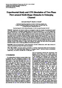
Wake width ratio (W/D)
7.0
6.0 5.0 4.0 3.0 2.0 1.0 0.0 3.0
4.0 5.0 Spacing ratio (L/D)
6.0
d/D = 0.5 d/D = 1
Figure 14: Wake width ratio versus spacing ratio.
(a) By applying this method to simulate flow past two cylinders in tandem and comparing the results with others’ work, it showed that the results have better accuracy and the computation costs less time. The credibility and the viability were verified. The method will have broad application in large-scale computation in the future. (b) The diameter ratio plays an important role in flow past two cylinders in tandem. The upstream cylinder with smaller diameter will decrease the vortex volume and the interference between two cylinders. With a decreasing of 𝑑/𝐷, the vortices behind the upstream cylinder appear more but smaller. Meanwhile, with an increasing spacing ratio 𝐿/𝐷, the wake becomes narrower at 𝑑/𝐷 = 0.5 but becomes wider at 𝑑/𝐷 = 1. (c) The critical spacing ratio increases with the diameter ratio increasing. Moreover, the critical spacing ratio at 𝑑/𝐷 = 1 is between 3 and 4, and it is smaller than 3 at 𝑑/𝐷 = 0.5. In real word engineering, the structure of cylinders is more complicated, which should be considered in future study.
Competing Interests The authors declare that they have no competing interests.
spacing ratio at 𝑑/𝐷 = 1 is between 3 and 4, and the critical spacing ratio at 𝑑/𝐷 = 0.5 is smaller than 3. This phenomenon coincides with what we know: decreasing 𝑑/𝐷 leads to the narrower wake and smaller vortices after the upstream cylinder [19]; before 𝐿/𝐷 reaches the critical value, the vortex street is suppressed between the two cylinders [30]. To explain the mechanism behind this, wake width (𝑊) is measured for Figures 10–13 and wake width ratio is defined by 𝑊/𝐷; see Figure 14. At 𝑑/𝐷 = 0.5, the wake and vortices behind upstream cylinder are narrower and smaller, which reduces the interference between the two cylinders, leading to the narrower wake behind downstream cylinder as well. At 𝑑/𝐷 = 1 and 𝐿/𝐷 = 3, the vortex street is suppressed behind the upstream cylinder. Consequently, the wake width is narrower compared to the case at 𝑑/𝐷 = 0.5, 𝐿/𝐷 = 3. However, the wake behind the upstream cylinder is no longer suppressed when keep increasing the spacing ratio. Thus, the interference increases. At 𝑑/𝐷 = 1, the wake behind the upstream cylinder is wider than at 𝑑/𝐷 = 0.5. The increasing of spacing ratio will even cause wider wake behind the downstream cylinder due to stronger interference, until two independent vortex streets occur.
Acknowledgments The authors would like to thank Mr. Cansen Zhen for some of numerical experiments at early stage. The National Science Foundation of China, Grants 11202248 and 11572356, supports this work.
References [1] D. Sumner, “Two circular cylinders in cross-flow: a review,” Journal of Fluids and Structures, vol. 26, no. 6, pp. 849–899, 2010. [2] J. Wu, L. W. Welch, M. C. Welsh, J. Sheridan, and G. J. Walker, “Spanwise wake structures of a circular cylinder and two circular cylinders in tandem,” Experimental Thermal and Fluid Science, vol. 9, no. 3, pp. 299–308, 1994. [3] S. Mittal, V. Kumar, and A. Raghuvanshi, “Unsteady incompressible flows past two cylinders in tandem and staggered arrangements,” International Journal for Numerical Methods in Fluids, vol. 25, no. 11, pp. 1315–1344, 1997. [4] W. Jester and Y. Kallinderis, “Numerical study of incompressible flow about fixed cylinder pairs,” Journal of Fluids and Structures, vol. 17, no. 4, pp. 561–577, 2003. [5] Y. Bao, D. Zhou, and C. Huang, “Numerical simulation of flow over three circular cylinders in equilateral arrangements at low
8
[6]
[7]
[8]
[9]
[10]
[11]
[12]
[13]
[14]
[15]
[16]
[17]
[18]
[19]
[20]
[21]
[22]
Mathematical Problems in Engineering Reynolds number by a second-order characteristic-based split finite element method,” Computers and Fluids, vol. 39, no. 5, pp. 882–899, 2010. F. Xu and J.-P. Ou, “Numerical simulation of vortex-induced vibration of three cylinders subjected to a cross flow in equilateral arrangement,” Acta Aerodynamica Sinica, vol. 28, no. 5, pp. 582–590, 2010. A. Zhang and L. Zhang, “Numerical simulation of three equispaced circular cylinders,” Chinese Journal of Applied Mechanics, vol. 20, no. 1, pp. 31–36, 2003. K. K. Chen, J. H. Tu, and C. W. Rowley, “Variants of dynamic mode decomposition: boundary condition, Koopman, and Fourier analyses,” Journal of Nonlinear Science, vol. 22, no. 6, pp. 887–915, 2012. H. Ding, C. Shu, K. S. Yeo, and D. Xu, “Numerical simulation of flows around two circular cylinders by mesh-free leastsquare-based finite difference methods,” International Journal for Numerical Methods in Fluids, vol. 53, no. 2, pp. 305–332, 2007. Z. Han, D. Zhou, Y. Chen, X. Gui, and J. Li, “Numerical simulation of cross-flow around multiple circular cylinders by spectral element method,” Acta Aerodynamica Sinica, vol. 32, no. 1, pp. 21–37, 2014. P. Hao, G. Li, L. Yang, and G. Chen, “Large eddy simulation of the circular cylinder flow in different regimes,” Chinese Journal of Applied Mechanics, vol. 29, no. 4, pp. 437–443, 2012. A. G. Kravchenko and P. Moin, “Numerical studies of flow over a circular cylinder at ReD=3900,” Physics of Fluids, vol. 12, no. 2, pp. 403–417, 2000. G. V. Papaioannou, D. K. P. Yue, M. S. Triantafyllou, and G. E. Karniadakis, “Three-dimensionality effects in flow around two tandem cylinders,” Journal of Fluid Mechanics, vol. 558, pp. 387– 413, 2006. A. Kumar and R. K. Ray, “Numerical study of shear flow past a square cylinder at reynolds numbers 100, 200,” Procedia Engineering, vol. 127, pp. 102–109, 2015. J. O. Pralits, F. Giannetti, and L. Brandt, “Three-dimensional instability of the flow around a rotating circular cylinder,” Journal of Fluid Mechanics, vol. 730, pp. 5–18, 2013. G. Schewe, “Reynolds-number-effects in flow around a rectangular cylinder with aspect ratio 1:5,” Journal of Fluids and Structures, vol. 39, pp. 15–26, 2013. F. X. Trias, A. Gorobets, and A. Oliva, “Turbulent flow around a square cylinder at Reynolds number 22,000: a DNS study,” Computers and Fluids, vol. 123, pp. 87–98, 2015. M. Zhao, L. Cheng, B. Teng, and G. Dong, “Hydrodynamic forces on dual cylinders of different diameters in steady currents,” Journal of Fluids and Structures, vol. 23, no. 1, pp. 59–83, 2007. M. Mahbub Alam and Y. Zhou, “Strouhal numbers, forces and flow structures around two tandem cylinders of different diameters,” Journal of Fluids and Structures, vol. 24, no. 4, pp. 505–526, 2008. Y. Ding-Yong, L. Hong-Chao, and W. Chang-Hai, “Numerical simulation of viscous flow past two tandem circular cylinders of different diameters,” Periodical of Ocean University of China, no. 2, pp. 160–165, 2012. P. Zhang, Z.-D. Su, L.-D. Guang, and Y.-L. Li, “Effect of the diameter change on the flow past three cylinders,” Journal of Hydrodynomics, vol. 27, no. 5, pp. 554–560, 2012. Q. Yao and H. Kanayama, “A coupling analysis of thermal convection problems based on a characteristic curve method,”
[23]
[24]
[25] [26]
[27]
[28]
[29]
[30]
Theoretical and Applied Mechanics Japan, vol. 59, pp. 257–264, 2011. Q. Yao and Q. Zhu, “A pressure-stabilized Lagrange-Galerkin method in a parallel domain decomposition system,” Abstract and Applied Analysis, vol. 2013, Article ID 161873, 13 pages, 2013. Q. Yao and H. Zhu, “Numerical simulation of hydrogen dispersion behaviour in a partially open space by a stabilized balancing domain decomposition method,” Computers and Mathematics with Applications, vol. 69, no. 10, pp. 1068–1079, 2015. F. Brezzi and M. Fortin, Mixed and Hybrid Finite Element Methods, Springer, New York, NY, USA, 1991. Q.-H. Yao and Q.-Y. Zhu, “Investigation of the contamination control in a cleaning room with a moving AGV by 3D largescale simulation,” Journal of Applied Mathematics, vol. 2013, Article ID 570237, 10 pages, 2013. F. Brezzi and J. Douglas, “Stabilized mixed methods for the Stokes problem,” Numerische Mathematik, vol. 53, no. 1-2, pp. 225–235, 1988. J. Mandel, “Balancing domain decomposition,” Communications in Numerical Methods in Engineering, vol. 9, no. 3, pp. 233– 241, 1993. A. Toselli and O. B. Widlund, Domain Decomposition Methods—Algorithms and Theory, Springer, Berlin, Germany, 2005. M. M. Zdravkovich, “REVIEW—review of flow interference between two circular cylinders in various arrangements,” Journal of Fluids Engineering, vol. 99, no. 4, pp. 618–633, 1977.
Advances in
Operations Research Hindawi Publishing Corporation http://www.hindawi.com
Volume 2014
Advances in
Decision Sciences Hindawi Publishing Corporation http://www.hindawi.com
Volume 2014
Journal of
Applied Mathematics
Algebra
Hindawi Publishing Corporation http://www.hindawi.com
Hindawi Publishing Corporation http://www.hindawi.com
Volume 2014
Journal of
Probability and Statistics Volume 2014
The Scientific World Journal Hindawi Publishing Corporation http://www.hindawi.com
Hindawi Publishing Corporation http://www.hindawi.com
Volume 2014
International Journal of
Differential Equations Hindawi Publishing Corporation http://www.hindawi.com
Volume 2014
Volume 2014
Submit your manuscripts at http://www.hindawi.com International Journal of
Advances in
Combinatorics Hindawi Publishing Corporation http://www.hindawi.com
Mathematical Physics Hindawi Publishing Corporation http://www.hindawi.com
Volume 2014
Journal of
Complex Analysis Hindawi Publishing Corporation http://www.hindawi.com
Volume 2014
International Journal of Mathematics and Mathematical Sciences
Mathematical Problems in Engineering
Journal of
Mathematics Hindawi Publishing Corporation http://www.hindawi.com
Volume 2014
Hindawi Publishing Corporation http://www.hindawi.com
Volume 2014
Volume 2014
Hindawi Publishing Corporation http://www.hindawi.com
Volume 2014
Discrete Mathematics
Journal of
Volume 2014
Hindawi Publishing Corporation http://www.hindawi.com
Discrete Dynamics in Nature and Society
Journal of
Function Spaces Hindawi Publishing Corporation http://www.hindawi.com
Abstract and Applied Analysis
Volume 2014
Hindawi Publishing Corporation http://www.hindawi.com
Volume 2014
Hindawi Publishing Corporation http://www.hindawi.com
Volume 2014
International Journal of
Journal of
Stochastic Analysis
Optimization
Hindawi Publishing Corporation http://www.hindawi.com
Hindawi Publishing Corporation http://www.hindawi.com
Volume 2014
Volume 2014