Large-scale-integrated silicon photonics using microdisk and microring resonators (invited) Andrew W. Poon, Shaoqi Feng, Hong Cai, Xianshu Luo and Hui Chen Photonic Device Laboratory, Department of Electronic and Computer Engineering, The Hong Kong University of Science and Technology, Clear Water Bay, Hong Kong Email:
[email protected] ABSTRACT We review our recent work on silicon photonic devices for on-chip optical interconnects and optofluidics. On the optical interconnects front, we demonstrate coupled-resonator optical waveguides with gapless inter-cavity coupling for on-chip wide-bandwidth high-order optical channel filters and optical delay lines. We propose a 5×5 matrix switch comprising two-dimensionally cascaded microring resonator-based electrooptic switches for network-on-chip applications and demonstrate a 2×2 matrix switch as a proof-of-concept. We demonstrate cavity-enhanced photocurrent generation in a p-i-n diode embedded microring resonator for wavelength-selective photodetection and monitoring on-chip optical networks. We also investigate a serial-cascaded double-microring-based silicon photonic circuit for high-speed on-chip clock-recovery applications. On the optofluidics front, we study silicon nitride based waveguides with integrated microfluidic channels for optical manipulation of microparticles. Keywords: silicon photonics, microresonators, optical interconnects, coupled-resonator optical waveguides, optical delay, photodetection, network-on-chip, optofluidics
1. INTRODUCTION Over the past few years, a host of discrete on-chip silicon photonic devices have been demonstrated as potential building blocks for optical interconnects including lasers,1, 2 modulators,3-5 switches,6, 7 filters8, 9, delays10, 11 and photodetectors.12-14 Based on these milestones on discrete components, silicon photonic technologies are evolving towards device integration. C. Batten et al.15 proposed a photonic link comprising off-chip laser sources, microring resonator-based filters/modulators and silicon germanium photodetectors for dense wavelength division multiplexing. L. Chen et al.16 reported an on-chip optical link for 3-Gbit/s data transmission with ~120-fJ/bit energy consumption using micrometer-scale ring-resonator modulators and waveguide-integrated germanium photodetectors. S. Park et al.17 demonstrated monolithic integration of germanium photodiodes and silicon wire-based variable optical attenuators. Silicon photonics also find potential applications in the field of optofluidics. The development of optofluidic devices are largely enabled by recent advances in nanophotonic, nanofabrication and microfluidic technologies by which micron-scale fluidic channels and nanophotonic structures can be integrated in silicon, glass, polymer and elastomer materials.18 On the silicon optofluidics front, D. Erickson’s group19 demonstrated fluidic-based tunable spectral filtering in silicon photonic crystal circuits. R. Baets’ group20 fabricated a silicon microresonator-based biosensor with a footprint below 10×10 μm2. Here we report our recent progress in silicon photonic devices for optical interconnects and optofluidics. This paper is divided into the following sections. In section 2, we review our work on silicon photonic devices for optical interconnects
including (i) coupled-resonator optical waveguides with gapless inter-cavity coupling, (ii) microring-resonator-based electrooptic matrix switches and (iii) cavity-enhanced photocurrent generation in p-i-n diode embedded microring resonators. In section 3, we discuss a serial-cascaded double-microring-based silicon photonic circuit for high-speed on-chip clock-recovery applications. In section 4, we show optical manipulation of microparticles on a silicon nitride based waveguide. In section 5, we conclude the paper with discussion on future work.
2. SILICON PHOTONIC DEVICES FOR ON-CHIP OPTICAL INTERCONNECTS Coupled-resonator optical waveguides (CROWs) using planar microresonators have potential applications as on-chip wide-bandwidth high-order optical channel filters8, 9 and optical delay lines.10 Conventional microring-based CROWs rely on the evanescent inter-cavity coupling via narrow gap spacing. Previously, we proposed and demonstrated silicon photonic many-element CROWs21-23 using novel-shaped microdisk resonators, namely microspiral24-28 and double-notch-shaped microdisk resonators.22, 27, 29 Such microresonators enable gapless inter-cavity coupling via seamlessly jointed sub-micrometer-sized notches. Recently, we demonstrated such CROWs with up to 101 cascaded microdisks.30 We showed high-order filter response with maximum 3-dB linewidth of ~2.5 nm and measurement-limited side-mode suppression ratio of ~30 dB. We demonstrated a maximum optical delay of ~70 ps at the transmission band center from a 101-element CROW. Optical routers are essential components for optical networks-on-chip. Microring-resonator-based electrooptic switches are potential building blocks due to their high-speed operation and low-power consumption.31 We proposed a 5×5 matrix switch with key merits of i) tens to hundreds of micrometers-scale footprint, ii) gigabit/second-scale data transmission, iii) nanosecond-speed circuit-switching, iv) 100-μW-scale dc power consumption per link, and v) large-scale integration.31 We adopted multimode interference (MMI) crossing waveguides coupled with p-i-n diode embedded microring resonators as a switch element for the matrix switch.32-34 As a proof-of-concept, we demonstrated a switch element with 3-dB filter bandwidth of 56 GHz. The 10%-to-90% switch-on time and 90%-to-10% switch-off time are ~1.3 ns and ~1.2 ns. The dc power consumption for resonance wavelength tuning is ~0.93 nm/mW. We also demonstrated a 2 × 2 matrix switch comprising four cascaded switch elements with multi-wavelength 5-Gbit/s signal routing. Recently, we also demonstrated a dual-microring resonator coupled cross-connect switch element.35 We showed 10-Gbit/s NRZ optical signal routing. The switch on/off times are ~0.7/0.85 ns and the dc power consumption is ~0.9 nm/mW. We also investigated cavity-enhanced photocurrent generation in p-i-n diode embedded microring resonators.36 Photodetection in the 1.55-μm wavelength range on a silicon chip is challenging because silicon is essentially transparent in such wavelengths. However, the optical mode spatial overlap with the silicon waveguide surfaces gives rise to surface-state absorption (SSA). SSA-induced photocurrent generation can be enhanced by microresonators which enable optical field build-up inside the cavity. We demonstrated a 20-fold cavity-enhanced photocurrent generation with a cavity Q-factor of 8000. The on-resonance wavelength shows a responsivity of 0.25 mA/W upon -15-V bias. Such cavity-enhanced photocurrent generation could find applications in wavelength-selective photodetection and monitoring for on-chip optical networks.
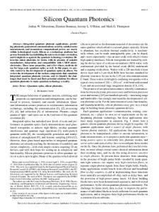
3. SILICON MICRORING RESONATOR-BASED CLOCK-RECOVERY PHOTONIC INTEGRATED CIRCUITS Current optical communication systems mostly employ non-return-to-zero (NRZ) data format. However, the NRZ format lacks a strong clock component. In order to recover the clock, NRZ format needs to be converted to pseudo-return-to-zero (PRZ) format.37 We studied the NRZ-to-PRZ format conversion using a silicon microring notch filter.38-40 We demonstrated NRZ-to-PRZ format conversion at a 3.6-Gbit/s data rate with a PRZ pulse width of ~38 ps. Recently, we also demonstrated 5-GHz sampling pulse generation using a serial-cascaded double-microring-based silicon photonic circuit.41 Here, we report our latest progress in this arena toward high-speed on-chip clock-recovery. 3.1 Principle Figure 1(a) shows the schematic of our proposed silicon microring-resonator-based on-chip clock-recovery photonic integrated circuit. Microring A (Ring A) resonator-based electro-optic (EO) tunable notch filter serves as an
NRZ-to-PRZ converter.38-40 Microring B (Ring B) resonator-based injection-type modulator of the same resonance wavelength as Ring A serves as a phase comparator. Both Ring A and Ring B are surrounded by lateral p-i-n diodes of identical design. In order to recover the clock, modulator Ring B can be driven by an external phase-locked loop for optical output phase detection. Figures 1(b) and (c) illustrate in the frequency- and time-domain the principles of the format conversion using narrowband notch filtering38-40 and phase comparison using microring-resonator-based modulators. We assume a 10-Gbit/s NRZ input signal with 35-ps rise- and fall-times. The notch filter suppresses the optical carrier λc and passes the side-band components resulting in PRZ pulses. The PRZ waveform depends on (i) the filter bandwidth and (ii) the filter extinction ratio, as discussed in Section 3.2. In order to compare the phase difference between the PRZ signal and the clock signal from a reference oscillator, we generate periodic optical sampling pulses in the vicinity of λc using the clock signal. The pulses periodically sample the PRZ signal. When the signal and the sampling pulses are in-phase, the modulator passes the signal. Otherwise, the modulator suppresses the signal. Thus, the output optical intensity is a function of the phase difference between the input signal and the clock signal.
Fig.1 (a) Schematic of the silicon microring-resonator-based on-chip clock-recovery photonic integrated circuit. (b), (c) Illustrations in the (b) frequency- and (c) time-domain of the NRZ-to-PRZ format conversion using a passive microring resonator and the phase comparison using an electro-optic microring resonator modulator.
3.2 Format conversion modeling
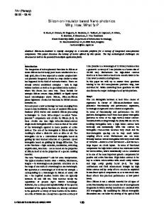
Figure 2(a) shows the modeled transmission spectra of microring resonator-based notch filters with various resonance Q-factors of 5×10³, 1×10⁴ and 2×10⁴. We adopt a Fourier-transform-based model.40 All the filters assume identical extinction ratio (ER) of 20 dB. Figure 2(b) shows the input 10-Gbit/s NRZ signal and the converted PRZ signals after the notch filters. The PRZ pulses appear at the leading and trailing edges of the NRZ pulse. High-Q notch filter transmits relatively more sideband frequency components and results in relatively pronounced PRZ pulses (with relatively high and wide pulse peaks).
Fig.2 (a) Modeled microring-resonator-based notch filter transmission spectra with various resonance quality factors of 5×10³, 1×10⁴ and 2×10⁴. (b) Modeled input 10-Gbit/s NRZ pulse with 35-ps rise- and fall-times and converted PRZ pulses after the notch filters. All the notch filters assume an extinction ratio of 20 dB.
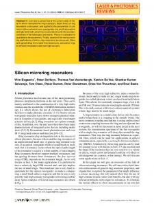
Figure 3(a) shows notch filter transmission spectra with various resonance ER values of 10, 20 and 30. All the filters have identical Q-factors of 1×10⁴. Figure 3(b) shows the input 10-Gbit/s NRZ signal and the converted PRZ signal after the notch filters. The PRZ pulses after the 10-dB notch filter display a plateau region corresponding to the high level of the NRZ signal. We attribute the plateau to the relatively weak optical carrier suppression. This also results in a widen PRZ pulse at the NRZ leading edge with significant overlap and interference with the PRZ pulse at the NRZ trailing edge. The PRZ pulses after the notch filter with ER of or above 20 dB display suppressed plateau.
Fig.3 (a) Modeled microring-resonator-based notch filter transmission spectra with various resonance extinction ratios of 10, 20 and 30. (b) Modeled input 10-Gbit/s NRZ pulse with 35-ps rise- and fall-times and converted PRZ pulses after the notch filters. All notch filters assume a quality factor of 1×10⁴.
3.3 Fabrication and characterization Figure 4(a) shows the optical micrograph of the fabricated double-microring-cascaded silicon photonic circuit. We fabricate the devices on a commercial silicon-on-insulator (SOI) wafer with a 0.34-μm-thick silicon device layer on a 1-μm-thick buried-oxide layer. The wire waveguide and the microrings have a designed width of 0.4 μm and an etched depth of 0.29 μm. The gap spacing between the waveguide and the microring is 0.35 μm. Both racetrack microrings are identically designed with arc radii of 25 μm and interaction lengths of 15 μm. The lateral p-i-n diode has an intrinsic region width of 1 μm across each microring (see the schematic cross section). The p+- and n+-doped regions have doping concentration of 2×10¹⁹ and 1×1020 cm-3. Microring resonator A works as a NRZ-to-PRZ format converter and B works as a phase comparator. The devices are defined by i-line (365 nm) photolithography, and etched by CF4-based reactive-ion plasma etching. The fabrication process is CMOS compatible. Figure 4(b) schematically shows the experimental setup for our circuit characterization. We use a bit-error-rate tester (BERT) to generate high-speed NRZ signals.
Fig.4 (a) Optical micrograph of the fabricated double-microring-cascaded silicon photonic circuit. Inset: cross-sectional schematic of the optical waveguide laterally integrated with the p-i-n diode. (b) Schematic of the experimental setup for circuit characterization.
Figure 5(a) shows the measured TE-polarized (electric field parallel to the chip) transmission spectra in the vicinity of 1537 nm, with two discrete resonances (λA = 1536.76 nm for Ring A, λB = 1537.04 nm for Ring B). We attribute the wavelength misalignment of ~ 0.28 nm to fabrication imperfections. The resonance Q-factors are ~ 4,000 and ~7,000 with ER of ~12 dB and ~8 dB. We perform the NRZ-to-PRZ waveform conversion using Ring A at carrier wavelength λc. The 5-Gbit/s NRZ input signal has a 10%-to-90% rise time and a 90%-to-10% fall time of ~90 ps. Figure 5(b) shows the measured PRZ signal with a ~ 50-ps pulse width and a peak ER of 5 dB. Figures 5(c) and (d) show the transmission spectrum and the waveform when the Ring B is forward-biased with a voltage of 0.87 V. Ring B with the blue-shifted resonance suppresses the PRZ signal. The 0.87-V bias compensates the resonance wavelength misalignment between the two resonances. Figures 5(e) and (f) show the transmission spectrum and the waveform when the Ring B is forward-biased with a voltage of 0.93 V. Ring B with the further blue-shifted resonance passes the PRZ signal. We can drive microring B with clock signal to sample the PRZ signal.
Fig.5 (a), (c), (e) Measured TE-polarized transmission spectra of the clock-recovery circuit with microring resonator B biased upon a voltage of (a) 0 V, (c) 0.87 V and (e) 0.93 V. (b), (d), (f) Measured waveform transmissions of a 5-Gbit/s NRZ optical signal through the clock-recovery circuit with microring resonator B biased upon a voltage of (b) 0 V, (d) 0.87 V and (f) 0.93 V.
4. OPTICAL MANIPULATION OF MICROPARTICLES IN SILICON NITRIDE BASED OPTOFLUIDIC CHIPS Waveguide-based optofluidic chips offer optical manipulation of microparticles in a small fluidic volume using guided surface wave. S. Gaugiran et al.42 demonstrated the trapping and moving of glass particles, yeast cells and red blood cells on a silicon nitride (SiN) waveguide using 1064-nm laser. A. H. J. Yang et al.43 reported the optical manipulation of nanoparticles in a liquid-core slot waveguide. K. Grujic et al.44 showed the sorting of polystyrene microparticles using a Y-branched optical waveguide. Here, we show our recent work on on-chip optical manipulation of microparticles in a silicon nitride based optofluidic chip. 4.1 Principle of waveguide-based optical manipulation
Fig.6 Schematic of optical manipulation of microparticles on a silicon nitride waveguide integrated with a water-filled fluidic channel.
Figure 6 shows the schematic of optical manipulation of microparticles using the surface wave of an integrated waveguide. An optical gradient force Fg1 in the lateral direction confines the microparticle towards the center of the waveguide. Another optical gradient force Fg2 in the vertical direction confines the microparticle near the waveguide surface. An optical scattering force Fs in the longitudinal direction propels the microparticle along the waveguide. Here we use numerical beam-propagation method to calculate the evanescent field distribution for various waveguide heights. Figure 7 inset shows the simulated TM mode-field intensity pattern (electric field perpendicular to the chip) at 1.55-μm wavelength for a waveguide height of 0.7 μm (with an etched depth of 0.63 μm). Figure 7 shows the evanescent field intensity at the top surface of the waveguide in the transverse direction with various waveguide heights of 0.5 μm, 0.7 μm and 0.9 μm.
Fig.7 Numerically calculated evanescent field intensity distribution along the top surface of the silicon nitride waveguide with different waveguide heights. Inset: TM-polarized mode-field intensity pattern of a 0.7-μm-height waveguide
4.2 Fabrication of integrated optofluidic devices We integrate the optical device layer with the microfluidic layer on a silicon substrate using CMOS process. For the optical device layer, we adopt SiN material for the key merits of (i) wide transparent window spanning from visible to infrared wavelengths, and (ii) high refractive index contrast to the silica cladding (~2/1.45) and to the water-filled fluidic channel (~2/1.33). Such high refractive index contrast enables small-cross-section integrated waveguides with substantially exposed evanescent field. Figure 8 shows the fabrication process of the integrated optofluidic device. We grow a 1.5-μm-thick wet thermal oxide as cladding on a silicon substrate. The SiN waveguide core layer is deposited using low-pressure chemical vapor deposition (LPCVD). The waveguide is patterned by photolithography followed by dry etching process. In order to better control the alignment between the optical layer and the microfluidic layer, we adopt the photolithography method to pattern the fluidic layer. We grow a layer of 6-μm-thick silica on top of the optical layer, and pattern the silica layer by photolithography and wet etching. A layer of cover glass is bonded onto the silica surface in order to seal the channel.
Fig.8 Fabrication process of the silicon nitride-based integrated optofluidic device.
4.3 Initial experimental results
Fig.9 (a) Optical micrograph of the fabricated optofluidic device. (b) Schematic of the experimental setup for optical manipulation of microparticles.
Figure 9(a) shows the optical micrograph of the fabricated optofluidic device. Figure 9(b) schematically shows the experimental setup. We inject the fluidic chamber with 1-μm polystyrene beads diluted in DI water. We image the beads in the fluidic channel by using a CCD camera with a 50x long-working-distance objective lens. We launch a ~110-mW 1.55-μm-wavelength TM-polarized laser light into the waveguide endface through a polarization-maintaining lensed fiber. The laser power measured from the waveguide transmission is ~3.6 mW. TM-polarization mode is preferred for its larger evanescent field amplitude on the waveguide top surface than TE-polarization mode. Figures 10 (a)-(b) show two microbeads (denoted as 1 and 2) driven along an illuminated 0.7-μm-height optical waveguide for the duration of 24s. Microbead 1 (near to the waveguide sidewall) is propelled by the optical waveguide against the water flow. While microbead 2 (on the waveguide surface) is also propelled by the optical waveguide but at a different velocity compared with that of microbead 1.
Fig.10 (a)-(b) Optically driven 1-μm-sized polystyrene microbeads on an illuminated SiN waveguide integrated with a microfluidic channel. (a) 0 s after laser is turned on. (b) 24 s after laser is turned on. (c) Schematic of the longitudinal forces on the microbead along the waveguide. Fflow: flow-induced force, Flight: optical scattering force.
We assume that within a certain small time slot the microbead is in equilibrium upon balancing between the optical scattering force Flight and the flow-induced force Fflow, shown in Fig.10 (c). Thus, we extract Flight from Fflow using the Stokes law: F = 3πudv, where u is the water viscosity of about 1.005×10⁻³ NS/m2 at 20 °C, d is the microbead diameter and v is the water velocity relative to the bead. We estimate the water flow rate from the velocity of free-moving microbeads in the channel within the same time slot (of 1s) and find an averaged value of ~14 μm/s. We estimate the optical scattering force to be about 130 fN within the duration of 24s.
5. CONCLUSION In summary, we reviewed our recent work on silicon photonic devices including (i) coupled-resonator optical waveguides with gapless inter-cavity coupling, (ii) cascaded microring-resonator-based electrooptic matrix switches and (iii) cavity-enhanced photocurrent generation in a p-i-n diode embedded microring resonator. We investigated a serial-cascaded double-microring-based silicon photonic circuit for high-speed on-chip clock recovery. We demonstrated 5-Gbit/s NRZ-to-PRZ format conversion using a microring notch filter and on-off switching of the PRZ signal with an electrooptic microring modulator. We also demonstrated optical manipulation of 1-μm-sized polystyrene beads in a silicon nitride-based integrated optofluidic device. The relative velocity of the optically driven microbeads is ~14 μm/s using 0.7-μm-thick silicon nitride waveguides. We will further develop on-chip optical clock recovery circuits and optofluidic circuits for manipulation of microparticles.
ACKNOWLEDGEMENTS This study was substantially supported by grants from the Research Grants Council of the Hong Kong Special Administrative Region, China (Projects 618506, 618707, 618308). We acknowledge Amonics Inc. for the 20-dBm EDFA. X. Luo acknowledges the fellowship support from the HKUST NANO program. We also acknowledge the HKUST Nanoelectronics Fabrication Facility for all the device fabrication.
REFERENCES [1] [2] [3] [4] [5] [6] [7] [8] [9] [10] [11] [12] [13]
Rong, H., Xu, S., Kuo, Y. H., Sih, V., Cohen, O., Raday, O. and Paniccia, M., “Low-threshold continuous-wave Raman silicon laser,” Nat. Photonics 1(4), 232-237 (2007). Fang, A. W., Jones, R., Park, H., Cohen, O., Raday, O., Paniccia, M. J. and Bowers, J. E., “Integrated AlGaInAs-silicon evanescent racetrack laser and photodetector,” Opt. Express 15(5), 2315-2322 (2007). Xu, Q., Manipatruni, S., Schmidt, B., Shakya, J. and Lipson, M., “12.5 Gbit/s carrier-injection-based silicon micro-ring silicon modulators,” Opt. Express 15(2), 430-436 (2007). Green, W. M. J., Rooks, M. J., Sekaric, L. and Vlasov, Y. A., “Ultra-compact, low RF power, 10 Gb/s silicon Mach-Zehnder modulator,” Opt. Express 15(25), 17106-17113 (2007). Liu, A., Liao, L., Rubin, D., Nguyen, H., Ciftcioglu, B., Chetrit, Y., Izhaky, N. and Paniccia, M., “High-speed optical modulation based on carrier depletion in a silicon waveguide,” Opt. Express 15(2), 660-668 (2007). Sherwood-Droz, N., Wang, H., Chen, L., Lee, B. G., Biberman, A., Bergman, K. and Lipson, M., “Optical 4x4 hitless silicon router for optical Networks-on-Chip (NoC),” Opt. Express 16(20), 15915-15922 (2008). Vlasov, Y., Green, W. M. J. and Xia, F., “High-throughput silicon nanophotonic wavelength-insensitive switch for on-chip optical networks,” Nat. Photonics 2(4), 242-246 (2008). Xia, F., Rooks, M., Sekaric, L. and Vlasov, Y., “Ultra-compact high order ring resonator filters using submicron silicon photonic wires for on-chip optical interconnects,” Opt. Express 15(19), 11934-11941 (2007). Li, Q., Soltani, M., Yegnanarayanan, S. and Adibi, A., “Design and demonstration of compact, wide bandwidth coupled-resonator filters on a silicon-on-insulator platform,” Opt. Express 17(4), 2247-2254 (2009). Xia, F., Sekaric, L. and Vlasov, Y., “Ultracompact optical buffers on a silicon chip,” Nat. Photonics 1(1), 65-71 (2007). Mookherjea, S., Park, J. S., Yang, S. H. and Bandaru, P. R., “Localization in silicon nanophotonic slow-light waveguides,” Nat. Photonics 2(2), 90-93 (2008). Yin, T., Cohen, R., Morse, M. M., Sarid, G., Chetrit, Y., Rubin, D. and Paniccia, M. J., “31GHz Ge n-i-p waveguide photodetectors on Silicon-on-Insulator substrate,” Opt. Express 15(21), 13965-13971 (2007). Ahn, D., Hong, C. Y., Liu, J., Giziewicz, W., Beals, M., Kimerling, L. C., Michel, J., Chen, J. and Kärtner, F. X.,
[14] [15]
[16] [17] [18] [19] [20] [21] [22] [23] [24] [25] [26] [27] [28] [29] [30] [31] [32] [33] [34] [35] [36] [37]
“High performance, waveguide integrated Ge photodetectors,” Opt. Express 15(7), 3916-3921 (2007). Park, H., Kuo, Y. H., Fang, A. W., Jones, R., Cohen, O., Paniccia, M. J. and Bowers, J. E., “A hybrid AlGaInAs-silicon evanescent preamplifier and photodetector,” Opt. Express 15(21), 13539-13546 (2007). Batten, C., Joshi, A., Orcutt, J., Khilo, A., Moss, B., Holzwarth, C., Popović, M., Li, H., Smithf, H., Hoyt, J., Kärtner, F., Ram, R., Stojanovic, V. and Asanovic, K., "Building many core processor-to-DRAM networks with monolithic silicon photonics," Proceedings - Symposium on the High Performance Interconnects, Hot Interconnects, 21-30 (2008). Chen, L., Preston, K., Manipatruni, S. and Lipson, M., “Integrated GHz silicon photonic interconnect with micrometer-scale modulators and detectors,” Opt. Express 17(17), 15248-15256 (2009). Park, S., Tsuchizawa, T., Watanabe, T., Shinojima, H., Nishi, H., Yamada, K., Ishikawa, Y., Wada, K. and Itabashi, S., "A monolithic integration of Ge Photodiodes with Si Variable Optical Attenuators," 2009 6th International Conference on Group IV Photonics, (2009). Xia, Y. and Whitesides, G. M., “Soft lithography,” Annu. Rev. Mater Sci. 28(1), 153-184 (1998). Erickson, D., Rockwood, T., Emery, T., Scherer, A. and Psaltis, D., “Nanofluidic tuning of photonic crystal circuits,” Opt. Lett. 31(1), 59-61 (2006). De Vos, K., Bartolozzi, I., Schacht, E., Bienstman, P. and Baets, R., “Silicon-on-Insulator microring resonator for sensitive and label-free biosensing,” Opt. Express 15(12), 7610-7615 (2007). Luo, X. and Poon, A. W., "50-element cascaded-resonator devices with gapless non-evanescent coupling using double-notch-shaped microdisks on a silicon chip," 2008 5th International Conference on Group IV Photonics, 350-352 (2008). Luo, X. and Poon, A. W., “Double-notch-shaped microdisk resonator devices with gapless coupling on a silicon chip,” Chin. Opt. Lett. 7(4), 296-298 (2009). Luo, X. and Poon, A. W., "101-element cascaded-microdisk resonators on a silicon chip," in Proc. Conference on Lasers and Electro-Optics 2009, Paper CMAA3, (2009). Lee, J. Y., Luo, X. and Poon, A. W., “Reciprocal transmissions and asymmetric modal distributions in waveguide-coupled spiral-shaped microdisk resonators,” Opt. Express 15(22), 14650-14666 (2007). Luo, X. and Poon, A. W., “Coupled spiral-shaped microdisk resonators with non-evanescent asymmetric inter-cavity coupling,” Opt. Express 15(25), 17313-17322 (2007). Luo, X., Lee, J. Y. and Poon, A. W., "Coupled spiral-shaped microdisk resonators with asymmetric non-evanescent coupling,", 2007 4th International Conference on Group IV Photonics, 1-3 (2007). Poon, A. W., Luo, X., Chen, H., Fernandes, G. E. and Chang, R. K., “Microspiral resonators for integrated photonics,” Optics & Photonics News 19(10), 48-53 (2008). Poon, A. W., Luo, X., Zhou, L., Li, C., Lee, J. Y., Xu, F., Chen, H. and Hon, K. Y., [Microresonator-based devices on a silicon chip: novel shaped cavities and resonance coherent interference], Boca Raton, 211-263 (2009). Luo, X., Li, C. and Poon, A. W.,"Double-notch-shaped microdisk resonator-based devices in silicon-on-insulator," in Proc. Conference on Lasers and Electro-Optics 2008, paper CTuNN7, (2008). Luo, X. and Poon, A. W., “Many-element coupled-resonator optical waveguides using gapless-coupled microdisk resonators,” Opt. Express 17(26), 23617-23628 (2009). Poon, A. W., Luo, X., Xu, F. and Chen, H., “Cascaded microresonator-based matrix switch for silicon on-chip optical interconnection,” Proc. IEEE 97(7), 1216-1238 (2009). Xu, F. and Poon, A. W., “Silicon cross-connect filters using microring resonator coupled multimode-interference-based waveguide crossings,” Opt. Express 16(12), 8649-8657 (2008). Xu, F. and Poon, A. W., "Multimode-interference waveguide crossing coupled microring-resonator-based switch nodes for photonic networks-on-chip," in Proc. Conference on Lasers and Electro-Optics 2008, (2008). Poon, A. W., Xu, F. and Luo, X., "Cascaded active silicon microresonator array cross-connect circuits for WDM networks-on-chip," Proc. SPIE 6898, 689812 (2008). Luo, X., Feng, S. and Poon, A. W., "Dual-microring resonator-coupled cross-connect switch element for on-chip optical interconnection," 2009 14th OptoElectronics and Communications Conference, (2009). Chen, H., Luo, X. and Poon, A. W., “Cavity-enhanced photocurrent generation by 1.55 mm wavelengths linear absorption in a p-i-n diode embedded silicon microring resonator,” Appl. Phys. Lett. 95(17), 171111(2009). Li, X., Kim, C. and Li, G., “All-optical passive clock extraction of 40 Gbit/s NRZ data using narrow-band filtering,” Opt. Express 12(14), 3196-3203 (2004).
[38] [39] [40] [41] [42] [43] [44]
Poon, A. W., Zhou, L., Li, C., Hon, N. K. and Chen, H., "Microring and microdisk resonator integrated circuits on a silicon chip," Proc. SPIE 6476, 647607 (2007). Zhou, L., Chen, H. and Poon, A. W., "NRZ-to-PRZ format conversion using silicon second-order coupled-microring resonator-based notch filters," In Proc. Conference on Lasers and Electro-Optics 2007, (2007). Zhou, L., Chen, H. and Poon, A. W., “On-chip NRZ-to-PRZ format conversion using narrow-band silicon microring resonator-based notch filters,” J. Lightwave Technol. 26(13), 1950-1955 (2008). Luo, X., Chen, H., Feng, S. and Poon, A. W., "A serial-cascaded double-microring-based silicon photonic circuit for high-speed on-chip clock-recovery applications," 2009 4th International Conference on Group IV Photonics, (2009). Gaugiran, S., Gétin, S., Fedeli, J. M., Colas, G., Fuchs, A., Chatelain, F. and Dérouard, J., “Optical manipulation of microparticles and cells on silicon nitride waveguides,” Opt. Express 13(18), 6956-6963 (2005). Yang, A. H. J., Moore, S. D., Schmidt, B. S., Klug, M., Lipson, M. and Erickson, D., “Optical manipulation of nanoparticles and biomolecules in sub-wavelength slot waveguides,” Nature 457(7225), 71-75 (2009). Grujic, K., Hellesø, O. G., Hole, J. P. and Wilkinson, J. S., “Sorting of polystyrene microspheres using a Y-branched optical waveguide,” Opt. Express 13(1), 1-7 (2005).