Large Scale Network Simulation Based on Hi-Fi Approach. ∗ Vitaly A. Antonenko1 , Ruslan L. Smelyanskiy2 and Andrey V. Nikolaev2 1
Moscow State University, Applied Research Center for Computer Networks, Moscow, Russian Federation
[email protected],
[email protected] 2 Moscow State University, Applied Research Center for Computer Networks, Moscow, Russian Federation
[email protected],
[email protected] 3 Applied Research Center for Computer Networks, Moscow, Russian Federation
[email protected]
Abstract Simulation of Large Scale Networks (LSN) has abroad application area. However, so far fine grain simulation of LSN faced with the problem of high dimension mathematical model and, consequently, the results were not precise. The scalable Network Prototyping Simulator (NPS), which allow surmount the problems, is presented in this paper. NPS is based on OS Linux lightweight virtualization containers (LXC) technics. The approach used in NPS allows achieving high fidelity simulation results, close to network emulation. Unlikely the emulation approach NPS allows to work with LSN networks. To achieve systems scalability authors used distributed architecture. Like any distributed system, NPS needs a time management mechanism. In resent paper, authors discuss and propose the time synchronization and the management mechanism for NPS.
1
Introduction
The network simulation is the effective method for the network operation analysis. In the scope of this analysis are: estimation of different indexes of network performance (throughput, end-to-end delay, etc.); to show to what extend the network resources are well balanced for different workloads and what the influence a malicious code can do on a specific network; do some changes in the network topology and resources allocation in it will give us a proper results; and many others. When we talk about a network simulation, we have keep in mind that a simulation model is a result of trade-off between the level of detailed description of a network, the complexity of a network description, the precision of a network operation prediction, hardness of a network model identification and calibration [1]. In its turn the details and the balance in this trade-off is the consequence of what kind of a mathematical model was chosen for the simulation model. Under the term Large Scale network (LSN) we will keep in mind a network with no less than 105 − 106 nodes. Researchers, taking in consideration such scale, had to use queuing theory techniques for mathematical model development with statistical averaging of many network ∗ This
work was supported by the Skolkovo Innovation Center under Grant 79 dated 02.07.2012.
1
easychair: Running title head is undefined.
easychair: Running author head is undefined.
operation parameters. An averaging was used to simplify the model to reduce its size. The price of this simplification is a precision of prediction of real network operation. The approach to the SDN network emulation based on light virtualization techniques called the Hi-Fi approach and described in the paper [2]. The Hi-Fi approach was proposed to the network environment emulation for the SDN controller application development. The proposed approach allows an emulator for the SDN network to be developed with high level of confidence (this is why it called the Hi-Fi approach). In this paper we propose how the Hi-Fi approach can be used for the LSN simulation for both SDN and traditional network, like TCP/IP based one. A simulation system has to have the following components: run-time environment, modeling time management subsystem, model description and validation subsystem, modeling experiment data repository and analytic tools, modeling experiment data visualization subsystem, model components library, model composer [3]. In the paper in hand we focus on the following components: run-time environment organization and modeling time management subsystem.
2
Related Work
A network operation model consists of three main parts: the description of network topology and resources; the description of traffic flows and workload; the description of traffic processing. Considering the Large Scale Network (LSN) topology we have to keep in mind an enormous complexity of such network. Let us remind that we consider network to be LSN, if it has no less that 106 nodes. There are several ways to manipulate with the LSN topology. However in some cases there is no topology description at all, e.g. classical epidemic simulation model of computer worm propagation [4]. Usually network topology is represented as a graph (EmuLab [5], NS-3 [6], SSFnet [7]). A traffic representation is a trade-off between accuracy and complexity of the model. On the level of the high accuracy (fine granularity) we represent traffic as flow of packets. In this case traffic is represented as a set of parameters (rate, losses, delays and etc.). The specific values of these parameters can be generated by mathematical functions or taking from real network traces. As a consequence the traffic processing should be described on packet level, too. Such description is not so easy and painstaking. A traffic processing is usually represented as traffic agent like in NS-3, SSFnet systems. The main goal of this agent is to generate traffic forwarding rules and to simulate traffic exchange service (network protocols of some level) among other traffic agents (including time delay caused by traffic processing service). Follow [2] a network simulation system which allow a precise description of network topology and resources, a precise simulation of network traffic and its processing on a packets level, we will define as the Hi-Fi system. Such systems are a convenient instrument of network operation analysis, because network simulation models made by it do not require a correctness proof or simplifying it greatly. This fact could have a significant boost effect on the research, because sometimes model correctness proof could require a comparable or even greater effort than building of model itself. The LSN simulation requires a lot of computational resources. This requirement leads to the need of the distributed simulation system, which requires the time synchronization problem solution [8]. The Hi-Fi Network Prototyping Simulator (NPS) is invented to simulate LSN [9] as a sandbox for: 2
easychair: Running title head is undefined.
easychair: Running author head is undefined.
• LSN operation analysis (malware propagation, forwarding network protocols convergence research, network performance testing (ex. maximum throughput, average delay/loss level)); • developing network applications (software for network devices, L5-L7 level applications). It is assumed that the mathematical model of simulated LSN is based on the formal model of LSN [10]. The current version of NPS allows simulate network operation with more than 30.000 vertex in topology. It should be noted that in the original paper [10] the Hi-Fi approach was applicable only to small networks (up to 2000 vertex in a graph). In [9] there is a detailed description of the NPS architecture. In recent paper we focus only on time management problem.
3
Time in LSN Formal Model
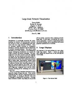
In this section we consider the time representation in the formal model [10] and time synchronization service in the run-time environment. In the formal model mentioned above it was assumed that the network has a single observer [11] with a unique discreet clock. Now let us consider the case with several observers, and each of them has its own clock. The indications of these clocks may be different. Let us recall, that the LSN formal model [10] is assumed to be divided into domains. A domain is a set of hosts linked with one another. It is assumed that the sets of hosts in different domains do not overlap. For example, let the domains are distributed between several machines; each has its own clock. We will assume that for each two observers is true that the difference between their clock indications is a constant. The LSN simulation model unlikely to calculate on a single machine. The only way to solve it is to build a distributed simulation system that consists of cluster machines. We would call these machines — cluster nodes. One of the major problem of distributed simulation is time synchronization among components of the simulation model. It is important because the whole simulation model ought to operate in a unique time, but in a distributed system there is no global clock to synchronize with. The model time speeds in a various system components are different because of different load, performance and other characteristics of system components (cluster nodes and links between them) [12]. The main goal of the simulation system time management service is a correct ordering of events in a model time. Accordingly to the problem examined in this paper, the clocks in the components of the LSN simulation model placed in different cluster nodes have to be synchronized (fig. 1). We need this service when the parameters of the physical link do not fit the parameters of the link in simulation model (logical link) mapped on the physical one. The time difference among of the different cluster nodes could be synchronized by using the optimistic time synchronization approach for distributed systems (in it simplified version). The main drawback of an optimistic scheme is a rollback [12]. Instead of rollback we propose to interpret the time differences violation as a packet lost or drop. Let ti , tj — clock indications on cluster nodes i and j correspondingly. We assume that at the initial time moment every cluster node clocks starts simultaneously (∆0ij = t0i − t0j = 0). For the time synchronization between domains placed on a different cluster nodes we will use the following rules: A if the timestamp of packet, received by i cluster node from j cluster node, is grater then clock indication of i cluster node plus link delay between these cluster nodes, i cluster node will wait for the time interval equal to ”∆ij + dllink ” to communicate with j node, where dllink - link delay between i and j cluster nodes; 3
easychair: Running title head is undefined.
easychair: Running author head is undefined.
Figure 1: Virtual topology mapping scheme. B if the timestamp of packet, received by i cluster node from j cluster node, is less then clock indication of i cluster node plus link delay between these cluster nodes, i cluster node will drop packets, because for node j there will be event from the past; C if the timestamp of packet, received by i cluster node from j cluster node, is equal to clock indication of i cluster node plus link delay between these cluster nodes, there is no necessity for time synchronization. To cover above described time management gap in the formal model let us add the Time Agent (TA) to the every domain in the LSN model. The time agent is responsible for the time synchronization between two communicating domains. Our time synchronization algorithm has two steps: 1. Once the mapping logical links onto physical ones is done, the maximum ratio physical link delay to logical link delay is calculated (Let us use Rmax for the maximum ratio). 2. Apply the normalizing transformation to all logical links of a model as follows: Rmax ·dllog , where dllog — logical link delay. It is proved that with proposed algorithm all packets in the simulated network will be arrived in a correct order. Saying ”correct order” we mean the packet order during simulation will be the same like a real network operation.
4
NPS Time Management Service
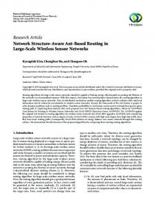
The Network Prototyping Simulator (NPS) is developed as the upper level software over Mininet that could combine several separate instances of the Mininet system into one cluster (fig. 2). Mininet is a rapid prototyping system [13]. The major goal of this system is fast development of OpenFlow controller applications. An OpenFlow controller is a core of Software-Defined Network [14] [15]. The main advantage of the Mininet is a network prototype implemented by it can be placed in a single laptop. 4
easychair: Running title head is undefined.
easychair: Running author head is undefined.
Figure 2: NSP cluster scheme. The NPS architecture consists of four main parts: NPS Supervisor Console; NPS OpenFlow Controller; NPS Cluster Node; NPS Network Service Library. The NPS Supervisor Console is the mean to configure, to send commands and to show outputs from several instances of Mininet via the SSH protocol. To establish the SSH connection with each Mininet instance the Paramiko library [16] is used. The NPS cluster node is a machine with Linux OS (Ubuntu 13.04) with several packages installed from public repository: the Python language interpreter [17]; Scapy-Python [18] — the library for Python for custom network packets generating and sniffing; and Mininet system [19]. The NPS cluster node should have two active Ethernet interfaces. The first one is to communicate with the NPS supervisor console, another one is to communicate with other cluster nodes. The NPS supervisor console uses the SSH protocol to control the NPS cluster nodes. The connection among NPS cluster nodes is deployed via an external interface mechanism, e.g. described in ”hwintf.py” in Mininet distribution kit. The NPS OpenFlow controller is used to set up traffic processing (forwarding policy) on links inside the NPS cluster node, and links that are mapped on physical links between cluster nodes. It is worth to mention that the NPS cluster nodes could be allocated between several OpenFlow controllers. This allocation mechanism is important for load balancing of traffic in the control plane among virtual switches in network model. The main stages of the NPS run-time environment operation are: 1. Initiate SSH session for each NPS cluster node. 2. Configure external interface among connected cluster nodes. 3. Parse input script with description of network topology, resources and network traffic. 4. Prepare and send specially generated input scripts to each cluster node. So the network graph is cutting into pieces and deploy each piece on separate cluster node. 5
easychair: Running title head is undefined.
easychair: Running author head is undefined.
5. Send network services configuration scripts to each cluster node. 6. Run the experiment. 7. At the end of the experiment, the NPS console sends exit-command to each cluster node and closes all SSH sessions. 8. (Optional) Visualizing results. There are two possible cases of mapping of communicating domains Di , Dj on cluster nodes: 1. Domain Di and domain Dj placed in the same cluster node. 2. Domain Di and domain Dj placed in the different cluster nodes. Generally speaking, there is the third case, when hosts from one domain are placed in different cluster nodes. But this case is not accepted by LSN formal model [10]. In the case 1 above the logical link between domain is placed in that cluster node. Inside cluster node there is a unique clock for all hosts, links, switches placed in this node which is local operating system clock. A link inside the cluster node represent as a pipe and this pipe always operate faster than any network connection through network interface, consequently case ”A” from section 3 is not possible. As a result there is no need for time synchronization if communicating domains placed in the same cluster node. In the second case the logical link between domain is mapped on the physical link between cluster nodes. The Physical link can operate slower that the logical one and become the reason of time desynchronization. The solve this problem we developed the Time Agent (TA), which operation process consists of several steps: • The TA sends several packets thought concrete links between external interfaces of different cluster nodes and calculates average round trip time (RTT). • Average RTT is divided by two and compared with the logical link delay. • If the link satisfy the delay, the model operation continue in normal mode. • If the link does NOT satisfy the delay, the TA calculates the ratio between the physical link delay and the logical one. • The maximum ratio is calculated among all external interfaces • All links increase the delay on maximum ratio (inside the cluster node and between cluster nodes). It should be mentioned that the TA is a optional module and in experiments where an NPS user does not need time synchronization, it could be turned off. In this mode the NPS system will only notify an NPS user about potentially incorrect links, but will not take any actions to manage the time. During preparing complex experiments an NPS user faces with the problem of network services configuration on each host in the domain. There are several difficulties: • Services configuring on each host is time-consuming process. • There are some technical challenges to launch several instances of network service daemon (ex. DHCP, FTP) that belong to different network namespaces on a single cluster node. 6
easychair: Running title head is undefined.
easychair: Running author head is undefined.
To solve that problem we developed a special framework, called Network Service Configuration framework (NSC), to automatize this configuration process. This framework is represented as a network services library. The NSC allows running plenty of preconfigured network services (such as DHCP, NTP, HTTP, MTA agent, FTP, etc) on the same cluster node. Using this framework provides time saving for NPS users who need to prepare the complex experiment with preconfigured network services.
5
Experiment Results and Discussion
In this section we described capabilities of the time management service. The idea is to prevent the packets dropping caused by link delays and network services time characteristics scaling. The expected results of this experiment are: • alerting about packet reordering or drop; • correcting link delays and network services time characteristic (using the TA) to prevent packets reordering or drop. Let us take a simple topology (fig. 3) that will be loaded on two cluster nodes connected by the physical link with delay dlphy = 0.11 ms (pic. 2). According to the NPS run-time environment operation sequences the network graph will be separated on two parts and mapped on different cluster nodes. In this case the one of the logical links will be mapped on physical link between cluster nodes. In the figure 4 green vertex are mapped on first cluster node, blue ones — on second cluster node; the black edge defines the logical link that is mapped on the physical link between cluster nodes. We suppose that an NPS user set the given logic link delay dllog = 0.018 ms (pic. 1).
Figure 3: Network graph.
Figure 4: Mapped Network graph.
Picture 1: Logical link ping output PING 127.0.0.1 (127.0.0.1) 56(84) bytes of 64 bytes from 127.0.0.1: icmp_seq =1 ttl =64 64 bytes from 127.0.0.1: icmp_seq =2 ttl =64 64 bytes from 127.0.0.1: icmp_seq =3 ttl =64 64 bytes from 127.0.0.1: icmp_seq =4 ttl =64 64 bytes from 127.0.0.1: icmp_seq =5 ttl =64
data . time =0.104 time =0.035 time =0.036 time =0.034 time =0.032
ms ms ms ms ms
Picture 2: Physical link ping output PING n001 (10.0.2.7) 56(84) bytes of data . 64 bytes from n001 (10.0.2.7) : icmp_seq =1 ttl =64 64 bytes from n001 (10.0.2.7) : icmp_seq =2 ttl =64 64 bytes from n001 (10.0.2.7) : icmp_seq =3 ttl =64 64 bytes from n001 (10.0.2.7) : icmp_seq =4 ttl =64 64 bytes from n001 (10.0.2.7) : icmp_seq =5 ttl =64
time =0.250 time =0.208 time =0.213 time =0.233 time =0.222
ms ms ms ms ms
7
easychair: Running title head is undefined.
easychair: Running author head is undefined.
As first case, we run the experiment when the TA is turn off and the NPS system operates without time management. We put the DHCP server in one part of network graph (on concrete host) and turn on DHCP clients on other hosts in the graph. The DHCP server timeout is set equal to the biggest RTT among hosts in network graph. The RTT value calculation based on logical links delays defined by an NPS user on every edge (dllog = 0.018 ms). The mostly interesting point is dlphy > dllog . That’s why the physical RTT will be bigger then the logical one. The result in this case (no time management) is: • All hosts, that are placed in the same with the DHCP server part of graph, received new IP addresses from 1.2.5.∗ subnetwork. • All hosts, that are placed in another part of graph, did NOT receive IP addresses and stayed with old IP addresses from 1.2.3.∗ subnetwork. The conclusion is that we have the inconsistency between expected behavior and real behavior during the simulation, because the network model configuration presupposed that all hosts ought to receive IP addresses from the DHCP server, but some hosts do not receive (pic. 3). That inconsistency caused, because the link delay between cluster nodes do not satisfy to the requirements of the logical link, defined by the an NPS user. As the second case, we repeat the experiment with the time management (the TA is turn on). dl ≈ 6.1 During the network model initialization we determine the maximum ratio Rmax = dlphy log between physical and logical links. After that, we make normalizing transformation to all logical links of the model as follows: Rmax · dllog , where dllog — logical link delay, even on links that are inside the cluster nodes. Also we would normalize, using Rmax , all time characteristics in all configured network services (in recent experiment there is only the DHCP server connection timeout). Here the result of the experiment (pic. 4).
Picture 3: Fail dhclient output. n001 dhclient : Internet Systems Consortium DHCP Client 4.2.4 n001 dhclient : Copyright 2004 -2012 Internet Systems Consortium . n001 dhclient : All rights reserved . n001 dhclient : For info , please visit https :// www . isc . org / software / dhcp / n001 dhclient : n001 dhclient : Listening on LPF / h9 - eth0 / de : a7 : d7 : dd :34: bf n001 dhclient : Sending on LPF / h9 - eth0 / de : a7 : d7 : dd :34: bf n001 dhclient : Sending on Socket / fallback n001 dhclient : DHCPDISCOVER on h9 - eth0 to 25 5. 2 55 .2 55 . 25 5 port 67 interval 2 ( xid =0 x9454a18 ) n001 dhclient : No DHCPOFFERS received . n001 dhclient : No working leases in persistent database sleeping .
Picture 4: Success dhclient output. n001 dhclient : Internet Systems Consortium DHCP Client 4.2.4 n001 dhclient : Copyright 2004 -2012 Internet Systems Consortium . n001 dhclient : All rights reserved . n001 dhclient : For info , please visit https :// www . isc . org / software / dhcp / n001 dhclient : n001 dhclient : Listening on LPF / h8 - eth0 /8 a :04:6 d : e0 :45: e6 n001 dhclient : Sending on LPF / h8 - eth0 /8 a :04:6 d : e0 :45: e6 n001 dhclient : Sending on Socket / fallback n001 dhclient : DHCPDISCOVER on h8 - eth0 to 25 5. 2 55 .2 55 . 25 5 port 67 interval 2 ( xid =0 x11e23d19 ) n001 dhclient : DHCPREQUEST of 1.2.5.96 on h8 - eth0 to 2 55 .2 5 5. 25 5. 2 55 port 67 ( xid =0 x11e23d19 ) n001 dhclient : DHCPOFFER of 1.2.5.96 from 1.2.3.21 n001 dhclient : DHCPACK of 1.2.5.96 from 1.2.3.21 n001 dhclient : bound to 1.2.5.96 -- renewal in 280 seconds .
It should be emphasized that the simulation model behavior completely corresponds to expected network operation and all hosts received their IP addresses from the DHCP server because time scaling of the simulation events (pic. 5) .The price of that correctness is the increasing time of the experiment. In our experiment time needed for simulation increased from 88.35 sec to 187.6 sec. Taking in consideration that the part of this time was spent for the network graph deployment on cluster nodes, we achieved the expected network model behavior. Picture 5: Hosts network interface configuration. h28 - eth0 Link encap : Ethernet HWaddr c6 :29: c0 :57:16:00 inet addr :1.2.5.90 Bcast :1.2.255.255 Mask :255.255.0.0 inet6 addr : fe80 :: c429 : c0ff : fe57 :1600/64 Scope : Link UP BROADCAST RUNNING MULTICAST MTU :1500 Metric :1 RX packets :412 errors :0 dropped :4 overruns :0 frame :0
8
easychair: Running title head is undefined.
easychair: Running author head is undefined.
TX packets :14 errors :0 dropped :0 overruns :0 carrier :0 collisions :0 txqueuelen :1000 RX bytes :46378 (46.3 KB ) TX bytes :1820 (1.8 KB ) ... ... h20 - eth0 Link encap : Ethernet HWaddr c2 : e7 :26:13:6 e : c0 inet addr :1.2.5.77 Bcast :1.2.255.255 Mask :255.255.0.0 inet6 addr : fe80 :: c0e7 :26 ff : fe13 :6 ec0 /64 Scope : Link UP BROADCAST RUNNING MULTICAST MTU :1500 Metric :1 RX packets :367 errors :0 dropped :6 overruns :0 frame :0 TX packets :14 errors :0 dropped :0 overruns :0 carrier :0 collisions :0 txqueuelen :1000 RX bytes :36766 (36.7 KB ) TX bytes :1820 (1.8 KB )
Finally, we can mention that the ratio Rmax is a constant. Therefore, the time-stamps of all network events can be easily recalculated from the result model output traces.
6
Conclusion
In this paper we presented the improvements of the formal LSN model concerning the time synchronization between model components and the proof their correctness. We presented the scalable NPS (Network Prototyping Simulator) system, which was improved with the time management algorithm specific to LSN (Large Scale Network) simulation. Also we showed, by the experiment, the use-case where such time synchronization was critical. These improvements were developed as the TA (Time Agent) in the NPS system. The developed NPS system provides a Hi-Fi approach to simulate an LSN network correct representation of network structure, traffic and traffic procession. There are two main advantages of the NPS system: 1. The NPS allows to simulate LSN network. There is no necessity for proving correctness of network model, produced by the NPS system; 2. The NPS can produce the time synchronization between cluster nodes, that helps to prevent errors during network simulation on cluster architecture. Such algorithm retains the advantages of the Hi-Fi approach even in the LSN simulation, where several cluster nodes are used. The NPS system offers an excellent opportunity for LSN operation analysis, network forwarding protocols developing and network control application (ex. the SDN controller applications) developing, to gain sandbox for complex experiments. The NPS system is scalable solution and perform the simulation of tens of thousands hosts in a single experiment. It is the great alternative between network emulators and the LSN analytic models. The NPS development was accompanied by the development of NSC (Network Service Configuration framework). This framework allows to automatize network services (ex. FTP, DHCP, SSH, SMTP) configuration and launching in complex experiments. The architecture of the NSC makes it easy to expand this library due to other specialized network services. Finally, Network Prototype Simulator is an open-source project. Walkthrough, installation instructions and examples could be find in [20].
References [1] D. Henclewood, W. Suh, M. Rodgers, M. Hunter, and R. Fujimoto, “A case for real-time calibration of data-driven microscopic traffic simulation tools,” in Proceedings of the Winter Simulation Conference, WSC ’12, pp. 148:1–148:12, Winter Simulation Conference, 2012.
9
easychair: Running title head is undefined.
easychair: Running author head is undefined.
[2] N. Handigol, B. Heller, V. Jeyakumar, B. Lantz, and N. McKeown, “Reproducible network experiments using container-based emulation,” in Proceedings of the 8th International Conference on Emerging Networking Experiments and Technologies, CoNEXT ’12, (New York, NY, USA), pp. 253–264, ACM, 2012. [3] A. G. Bakhmurov, A. P. Kapitonova, and R. L. Smeliansky, “Dyana: An environment for embedded system design and analysis.,” in TACAS (R. Cleaveland, ed.), vol. 1579 of Lecture Notes in Computer Science, pp. 390–404, Springer, 1999. [4] C. C. Zou, D. Towsley, and W. Gong, “Modeling and simulation study of the propagation and defense of internet email worm,” IEEE Transactions on Dependable and Secure Computing, vol. 4, 2007. [5] “Emulab homepage.” http://www.emulab.net/. [6] “Ns-3 homepage.” http://www.nsnam.org/. [7] “Scalable simulation framework homepage.” http://www.ssfnet.org/homePage.html. [8] R. Smelyansky, “Model of distributed computing system operation with time,” Programming and Computer Software, vol. 39, no. 5, pp. 233–241, 2013. [9] V. Antonenko and R. Smelyanskiy, “Global network modelling based on mininet approach.,” in Proceedings of the Second ACM SIGCOMM Workshop on Hot Topics in Software Defined Networking, HotSDN ’13, (New York, NY, USA), pp. 145–146, ACM, 2013. [10] V. A. Antonenko and R. L. Smelyanskiy, “Simulation of malicious activity in wide area networks,” Program. Comput. Softw., vol. 39, pp. 25–33, Jan. 2013. [11] R. L. Smelyanskiy, “On the theory of functioning of distributed computer systems,” pp. 161–182, 2001. [12] Y. K. R. Smeliansky, “Organization of synchronization algorithms in distributed simulation,” in Proceedings of 2nd Russian-Turkish seminar ”New High Information Technologies”, 1994. [13] B. Lantz, B. Heller, and N. McKeown, “A network in a laptop: rapid prototyping for softwaredefined networks,” in Proceedings of the 9th ACM SIGCOMM Workshop on Hot Topics in Networks, Hotnets-IX, (New York, NY, USA), pp. 19:1–19:6, ACM, 2010. [14] N. McKeown, T. Anderson, H. Balakrishnan, G. Parulkar, L. Peterson, J. Rexford, S. Shenker, and J. Turner, “Openflow: enabling innovation in campus networks,” SIGCOMM Comput. Commun. Rev., vol. 38, pp. 69–74, Mar. 2008. [15] B. Pfaff, J. Pettit, T. Koponen, K. Amidon, M. Casado, and S. Shenker, “e.a.: Extending networking into the virtualization layer,” in In: 8th ACM Workshop on Hot Topics inNetworks (HotNets-VIII).New YorkCity,NY(October 2009. [16] “Paramiko module main site.” http://www.lag.net/paramiko/. [17] “Python 2.7 documentation.” http://www.python.org/doc/. [18] “Python-scapy module main site.” http://www.secdev.org/projects/scapy/. [19] “Mininet github repo.” https://github.com/mininet/mininet. [20] “Network prototype simulator homepage.” http://anvial.github.io/MininetClusterEdition/.
10