Large-Scale Simulation Platform ENN TYUGU and PAVEL GRIGORENKO Institute of Cybernetics Tallinn Technical University Akadeemia tee 21, 12618 Tallinn ESTONIA
[email protected],
[email protected] http://www.cs.ioc.ee/~tyugu, http://www.cs.ioc.ee/~pavelg Abstract: - A large-scale simulation platform that includes various simulation engines and is intended for application in a variety of domains is considered. Conceptual design of platform and its implementation are described. The platform supports model-based software development and uses structural synthesis of programs for translation of declarative specification of simulation problems into executable code. Preprogrammed control structures are provided for distributed simulation. The platform is developed as open software and its extensions can be written in Java and C, and included into the simulation packages. Key-Words: - Large-scale simulation, Hybrid simulation, Model-based software, Extensible specification language.
1 Introduction
2 Design of the platform
This work concerns a project, the aim of which is to develop an open software platform for multipurpose and large-scale simulation. The term large-scale simulation is being used here for denoting both computationally intensive as well as heterogeneous (hybrid) simulation problems. We expect that, in the future, simulation problems will be not only more computationally heavy, but also considerably more complex in the sense that a single problem may require orchestrated usage of numerous simulation engines, and will be always performed in a distributed environment. The present situation and a short-term view of the large-scale simulation have been described in the reports [4], [5]. However, these reports are based on the experiences of experts in narrow application domains referring mainly to their own domains. We expect to see considerably more interaction between the different domains in the future. Although the Japanese Earth Simulator project that uses huge computing power is a successful example of large-scale simulation [6], we hope that the future of simulation belongs to fusion of different simulation tasks, first of all, in engineering domains performed by multidisciplinary teams.
In this section we first discuss requirements to a large-scale multipurpose simulation platform. Thereafter we present solutions on a quite abstract knowledge level, without implementation details. We are going to present the implementation of the core platform in the next section.
Viewed from a traditional simulation perspective, the present work concerns integrated software infrastructure of simulation platforms.
2.1 Requirements Requirements from the user’s point of view concern language, models, simulation engines, libraries and computing environments. We have to consider the usability, extensibility, maintainability and performance. 2.1.1 Language We need a language that is suitable for describing simulation problems as well as for describing new extensions to an existing simulation environment. In the other words – we need a knowledge representation language. This language must be extensible and easy to use. This can be achieved only by developing declarative language with a simple syntax and precise semantics. Graphical description of simulation objects is a natural requirement. Hence, the language must have a graphical representation. It is highly useful to have simple translation from graphical representation into textual representation. This will guarantee transparency of the graphical language.
2.1.2 Models Object models have always played a central role in the simulation software. Hence, it is natural to expect that the simulation platform will support model-based software development. In this case, models must be hierarchical with unlimited depth of hierarchy. 2.1.3 Simulation engines As we are developing an extensible and multipurpose simulation platform, we have to support several simulation engines – for discrete event simulation, for simulation of synchronous as well as asynchronous systems, for simulation of dynamic systems described by differential equations of different kind. We have also to support the development of new simulation engines. We have to guarantee the interoperability of several simulation engines to such extent that they could be used cooperatively in one and the same simulation. This can be achieved by developing simulation engines as regular components of the extensible simulation software. 2.1.4 Libraries Multi-purpose simulation in different domains requires large amount of domain-oriented software. This software should be presented in some form of component libraries that are composed according to rules that guarantee the interoperability. Tools for developing and handling the libraries must be included in the simulation platform. 2.1.5 Distributed computing and networking A large-scale simulation platform must support parallel and distributed computing on several levels. It is recommendable that networking will be included in the simulation software in a seamless way, including grid computing. 2.1.6 Interoperability Interoperability and portability can significantly improve the usability of the simulation software. Hence we require that the simulation platform must be easily portable and support interoperability with existing popular simulation and visualization tools, e.g. MathLab and Maple at least on the data exchange level.
2.2
Solutions
The basic principle of design of this platform is the separation of knowledge level from implementation. This is valid for architecture of the simulation platform and for the specification language as well
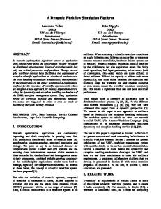
as for components that are developed for particular applications. 2.2.1 Knowledge architecture In order to present architecture of the simulation platform on knowledge level, without referring to its implementation, we use the concept of knowledge module as defined in [7]. A knowledge module (called also a knowledge system) is a knowledge representation and handling mechanism that must be presentable in a formal way, e.g. as an interpreted deductive system. We also use hierarchical bindings (presented here by solid lines) and operational bindings (presented by dashed lines) as described in [7] to show the interaction of the knowledge systems of our platform.
Visual KS
Textual KS
Domain 1
Domain k
Supporting knowledge systems (SKS)
Fig. 1. Knowledge architecture of the simulation platform Fig. 1 shows knowledge architecture of the simulation platform. Simulation domains (Domain 1 to Domain k) may have their own knowledge systems, but they are supported by knowledge representation and handling mechanisms, i.e. by supporting knowledge systems (SKS) included into the kernel of the platform. All simulation problems use common hierarchically connected knowledge systems of visual and textual languages for user interaction. 2.2.2 Languages The platform supports a textual and a visual specification language for specifying simulation problems. The textual specification language has a simple and a rather conventional syntax of declarative compositional languages. It enables one
to specify typed objects and bind them with each other by connecting their components by equalities. Numeric variables can be bound also by algebraic equations. Constant values can be assigned to variables of any type, as soon as the value has a textual representation. The textual specification language enables one also to specify programs by writing axioms about their applicability, i.e. by giving their pre- and postconditions. Types of components can semantically represent objects as well as relations between the objects. From a users point of view they are just concepts. Extensibility of the language is achieved by introduction of new types. The following is core of the language: 1. declaration of a component: ; This declaration specifies a component of a scheme with given type, and its name given by identifier. 2. binding: . = .; This statement specifies an equality between variables of components (ports). These variables are also attributes of attribute models of components. 3.
valuation: . = ; This statement defines a functional dependency with no inputs and with one output that receives a constant value. Form of axioms written in this language depends on the logic used by the simulation engine and underlying knowledge system. The following simple example of the usage of the specification language is a description of a minimax problem that uses components of types Max, Min and Model. The goal is to find the minimal value (depending on some variable y of the model object m) of the maximal values depending on a variable x on the model object m. (Here we use syntactic sugar for writing bindings in line with component declaration and omitting the name of the component.) Model m; Max max arg=m.x, val=m.result; Min min arg=m.y, val=max.maxval;
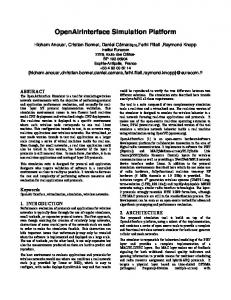
The visual language corresponds to textual language without axioms. Each type of objects can have a visual representation – an image supplied with ports
for binding objects with each other. A port is a component of an object made visible graphically. A specification is a scheme where objects are connected with each other via ports. The example from above has a visual specification as shown in Fig. 2.
max
x
m y
min
Fig. 2 Visual specification of the minimax problem 2.2.3 Model-based computing We foresee the development of several supporting knowledge systems of the platform. However, there is one SKS that has been developed for model-based computing. This SKS is intended for integration of all other SKS. It supports representation of knowledge both in logic and in a language of higherorder constraint networks. The specification language has been tailored already in such a way that it enables one to present models for this SKS. The specification language and representation of models support the hierarchical structure of models. If we look closer at the object max that has the type Max, we can see that it has a model described by the specification: Number Number Number (arg ⊃
arg; val; maxval; val)⊃ maxval{implementation};
The axiom here is written in a propositional language with propositions denoting the computability of objects. The axiom tells us that using implementation we can compute the maxval, i.e. the maximal value of a function, as soon as we can compute val from arg, where val stands for the value of the function and arg stands for the value of its argument. Model of Min is similar. Binding the variables arg, val etc. in a proper way, as we have done it in the example, gives us a possibility automatically to compose the algorithm and generate the code for solving the problem, i.e. for finding the value of min.minval. The model object m must have its own specification, and this can be
large and hierarchical itself, but in the simplest case it can be just a matrix, where x and y are number of a row and number of a column, and result is an element of the matrix in the respective position. Here we gave only a very superficial presentation of the model-based SKS of our platform. At a closer look one can see that our approach includes automatic composition of algorithms. This is performed by a method called structural synthesis of programs (SSP). For detailed description of this method we refer to [3]. 2.2.4 Java and open source We have chosen Java as the implementation platform of the kernel of the simulation platform. This is justified by the useful properties of Java: good portability and interoperability, support for distributed computing and open source ideology. The kernel of our platform has been developed in a way that does not restrict the usage of Java for programming of components. All Java types and classes can be used as types of objects in specifications. For instance, we have used the Number type in the models of Max and Min in the example above. Performance-critical components of any domain can be implemented in C or C++ and included as native methods in Java. This should guarantee sufficiently good performance of the whole system. 2.2.5 Distributed computing The simulation software must shield the domain experts from complexities of distributed computing. In the present case this can be achieved using Java RMI technology. In general, the logic of specifications does not prescribe only sequential computations. For instance, implementation of the axiom (arg ⊃ val)⊃ maxval can be written in such a way that it will compute the synthesized function from arg to val in parallel as it is illustrated in Fig. 3. arg
maxval
3 Implementation The implementation strategy of the present project is the following. First, a core platform has been implemented that supports an extensible specification language as well as component-based and model-based software development. Simulation engines are added and applications are developed gradually, porting some applications, e.g. simulation of dynamics of hydraulic systems [2] from older platforms. New libraries of components related to specific application domains will be developed cooperatively using the open source approach.
3.1 Components Having chosen Java as the software platform, we should accept Java classes as components. However, in general, the components must be supplied with specifications that represent their models and include information about their usability like in the case of Max in the example above. Therefore, we have introduced a concept of a metaclass that is a Java class supplied with a metainterface. Metainterface is a specification of interface variables and functional dependencies that bind these variables. It is written as a Java comment in the class text. The functional dependencies are implemented as methods of the class. Interface variables are abstract variables corresponding to the entities of a problem domain. Metaclass for Max for integer values (with some minor syntactic differences from a specification given above, e.g. -> instead of ⊃) is as follows: class Max {/*@ specification Max { int arg, val, maxval; [arg->val]->maxval{getMaxVal}; } @*/ public int getMaxVal(Subtask sbt) throws Exception { … return maxval; } }
(arg ⊃ val)⊃ maxval
val arg⊃val
Fig. 3. Parallel implementation of a subtask
In the visual language, a metaclass has a visual representation and a description of its visual properties as well. In Fig. 2 we already used possible visual representations of concepts Max, Min and Matrix with ports for binding variables arg, val, maxval etc. A metaclass together with its visual representation and features is called a visual class. Metaclasses and visual classes can be built
hierarchically, e.g. the minimax specified above can be declared to be a component itself.
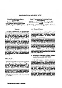
3.2 Core platform We have developed a software environment CoCoViLa that is the core platform for simulation [1]. This environment provides tools for developing visual classes and for constructing simulation packages. From a user’s point of view the tool consists of two components: Class Editor for the language development and Scheme Editor for using the language of schemes. 3.2.1 Class editor The tool for extending the language is Class Editor, which supports the language designer in defining the visual aspects of classes, and also their logical and interactive aspects. Fig. 4 shows the development of a component Adder in the window of the Class Editor. This component is used for computing output from given inputs in a package for simulation of dynamic systems. We can see the image of Adder with three ports and a pop-up window for defining properties of a highlighted port. Another pop-up window is for defining properties of the visual class, e.g. class fields that will be shown in a dialog window in the Scheme Editor. Functional properties of visual classes are implemented as metaclasses -- look at the class name “Adder” in the pop-up window for class properties.
Results of a visual language development are stored in a package that is usable by the Scheme Editor. 3.2.2 Scheme editor The Scheme Editor is a tool for the simulation expert. It is intended for developing schemes of simulated systems, compiling and running programs. It is used for compiling (synthesizing) programs from the schemes according to the specified semantics of a particular domain. The scheme editor is implemented using Java Swing library. It provides an interface for visual programming – putting together a scheme from visual images of classes. The environment generated for a particular visual language allows the user to draw, edit and compile visual sentences (schemes) through languagespecific menus and toolbars. Fig. 5 shows the scheme editor in use, when a package for simulating simple dynamic systems has been loaded. Such are systems described by ordinary differential equations. The scheme shown in the figure has been composed by connecting ports of components of the following types: Integrator, Adder, Clock and Graph. The toolbar at the top of the scheme is for adding objects and connections to the scheme. One pop-up window is for instantiating object attributes, another pop-up window is for manipulating the scheme – deleting and arranging objects etc. The scheme editor is fully syntax directed and the correctness of the scheme is forced during editing.
Fig. 4. Class Editor window A user interface (including toolbars and menus) is automatically generated from the language definition given by means of the Class Editor.
Fig. 5. Scheme Editor window The complete scheme is compiled into the program that represents the meaning of this scheme,
producing required result of simulation. Figure 6 shows the textual representation of a scheme presented in Figure 5 and the outcome of simulation that is a chart.
alias time = (*.time); alias state = (*.state); alias nextstate = (*.nextstate); alias initstate = (*.initstate); (state ∧ time ⊃ nextstate) ∧ initstate ⊃ process{impl};
3.3 Simulation engines The core platform supports interoperability between the simulation engines developed as metaclasses. Here we discuss briefly a simulation engine for state transition systems. This simulation engine is applicable in principle to all dynamic systems described by ordinary differential equations. In particular, in a prototype of our platform the RungeKutta method has been used in the method impl that the axiom describes. A control structure for simulation of state transition systems (including synchronous real time systems) is described by the following axiom: (state⊃nextstate)∧initstate⊃process{impl}
The nested implcation state ⊃ nextstate requires to compute the next state nextstate from a given state of a system. Implementation impl of this axiom produces the process, as soon as an initial state initstate and a program for computing nextstate form a given state are given. Different versions of this control structure have been used in simulation packages developed in a system that has been a prototype to our system and that uses the same kind of logic [8]. In such a case, to specify a simulation problem means to compose a model of the simulated system from predefined components. The software components with memory will have variables state and nextstate that all together constitute the state vectors state and nextstate of the simulated system. These state vectors are represented in the axiom given above. To bind states of components with the state vector, the specification language has a special alias construction and wildcard. The declaration alias state = (*.state);
means that state is a tuple, including all variables named state occurring in the components of the specified model. If the components are dependent on time, then the variable time can be added to the axiom and bound with time of every component together with state vectors. This gives us the following fragment of specification:
Fig. 6. Specification window and simulation result
3.4 Packages In conformance with the Java style, libraries of components are organized as packages. (See the “Package” command in the menu bar of the Scheme Editor in Fig. 5.) However, in our case, a package includes more than a Java package does. Besides metaclasses, it includes a package description in XML format that can be used by components even at runtime. We have developed prototypes of packages for simulation of dynamic systems, logic circuits, mechanical transmissions. A large package for simulation of hydraulic systems has been used in a prototype of the present platform for a number of years [2].
4 Conclusion Our experience shows that separation of knowledge level of the simulation platform from its implementation guarantees the flexibility of its implementation and provides user-friendliness of its usage, including a simple user model of the system. The decision of using Java without restrictions on its classes for component development has been
justified by the advantages we have got: good portability, easy extensibility, support to multithreading and network computing. The decision of relying on an advanced knowledge system that includes structural synthesis of programs has been justified by the easiness of implementation of the specification language and its extensions. Acknowledgements This work has been supported by the grant No. 6886 of the Estonian Science Foundation.
References: [1] P. Grigorenko, A. Saabas, E. Tyugu, Visual tool for generative programming. - ACM SIGSOFT Software Engineering Notes, Vol. 30, No. 5, 2005, pp. 249-252.
[2] G. Grossschmidt, M. Harf. Modelling and simulation of hydraulic systems in NUT programming environment. In: Viertes DeutchPolnises Seminar on Innovation und Fortschritt in der Fluidtechnik. Sopot. 2001, pp. 329-348. [3] M. Matskin and E. Tyugu. Strategies of structural synthesis of programs and its extensions. Computing and Informatics, Vol. 20, pp. 2001, 1 – 25. [4] Office of Science U.S. Department of Energy . A Science-Based Case for Large-Scale Simulation. http://www.pnl.gov/scales/docs/volume1_72dpi.pdf, 2003. [5] Office of Science U.S. Department of Energy. Building a Science-based Case for Large-scale Simulation, http://www.pnl.gov/scales/docs/ScaLeS _v2_ draft_toc.pdf, 2003. [6] Y.O. Takahashi, K. Hamilton, and W. Ohfuchi, Explicit global simulation of the mesoscale spectrum of atmospheric motions. Geophys. Res. Lett., L12812, doi:10.1029/2006GL026429, 2006. [7] E. Tyugu. Understanding Knowledge Architectures. Knowledge-Based Systems. Vol. 19, No. 1, 2006, pp. 50–56. [8] E. Tyugu and R. Valt. Visual programming in NUT. Journal of visual languages and programming, Vol. 8, 1997, pp. 523 - 544.