Proceedings of the 19th International Conference on Automation & Computing, Brunel University, London, UK, 13-14 September 2013
Large Scaled Multi-User MIMO System so called Massive MIMO Systems for Future Wireless Communication Networks Y.Mehmood; W.Afzal; F.Ahmad; U.Younas; I.Rashid; I.Mehmood Department of Electrical Engineering National University of Science & Technology Islamabad, Pakistan Emails:
[email protected];
[email protected] Abstract—The massive or large scaled multiple input multiple output (MIMO) systems have gained huge consideration due to high achievable data rates and connection reliability for future wireless networks. Multiple signal paths due to multiple antennas positioned at transmitter or receiver are responsible for large throughput. The eventual objective of using array of small antennas is that each single antenna will have small power consumption. The rapid increase in the number of wireless applications has put some limitations on conventional MIMO systems on channel capacity, energy and spectral efficiency. One of the possible solutions to overcome these limitations is to use large antenna arrays at the base stations or to some extent on the user equipments (UEs). The essential factors that must be considered before the deployment of massive MIMO systems include the broadcast models, channel estimation, placement ways with applications, uplink & downlink benefits and precoding procedures, expected achievable energy & spectral efficiencies, etc. In this article a comparison of massive MIMO is made with conventional MIMO. The authors discussed the massive MIMO system deployment scenarios, the best possible downlink precoding scheme for maximum achievable throughput, energy and spectral efficiency. Keywords- Massive MIMO; broadcast models; channel estimation; precoding procedures.
I.
INTRODUCTION
Comparing to various systems including single input single output (SISO), single input multiple outputs (SIMO) and multiple inputs single output (MISO), the multiple input multiple output (MIMO) uses multiple antennas at the transceiver to improve the system performance i.e. data rate and link reliability [1]. MIMO implementation has got its worth that is why; it is now identified as emerging and mature schemes in wireless communication to improve the data rates, system reliability, energy efficiency and by reducing the interference. It is the main reason of using MIMO in various standards like Universal Mobile Telecommunication System (UMTS) and Long Term Evolution (LTE) etc. [2]. For such systems we should have a keen knowledge about various demands for such large scaled multi user MIMO. Besides having the knowledge of the channel model for MIMO system, other requirements of knowledge includes placement ways with applications, uplink and downlink precoding ways and
achievable energy and spectral efficiency of scalable MIMO systems over conventional MIMO systems. The deployment of base stations with enormous antenna i-e massive MIMO base stations uses spatial multiplexing in order to get capacity almost 10 times as more as conventional MIMO systems, also can increase 100 of times the energy efficiency [3]. The article contains systems model, the energy and spectral efficiency, deployment ways for massive MIMO systems and downlink precoding schemes. The concentrated antenna arrays design has transmitted signal energy beam width more directional than the distributed antenna arrays deployment. Authors after making comparison, proposed better deployment scheme for massive MIMO base stations. To achieve high system capacity, energy and spectral efficiency, user equipment (UE) should have communication over orthogonal channel. The interference cancellation can be achieved by using strong downlink precoding techniques. The next portion of the article will explain uplink and downlink benefits. The uplink benefits can be inspected through detection of UEs at the transmitter using Matched Filter (MF) and Minimum Mean Square Error detection algorithm (MMSE). The downlink benefits i.e. signal transmission in massive MIMO is analyzed and results are compared for Dirty Paper Coding (DPC), Block Diagonalization (BD) and Tomlinson-Harashima precoding (THP). We just explained DPC and Linear Precoding schemes including Zero Forcing (ZF) and Minimum Mean Square Error (MMSE). BD can be implemented using ZF or MMSE, but we implemented using ZF. BD and THP are not explained in this article but only considered for simulation. In this research paper, the purpose of focusing large antenna arrays for future wireless communication is to highlight the benefits of massive MIMO over the conventional MIMO [2]. The section II is related to channel model. Section III explains the spectral efficiency. Some deployment schemes are discussed in section IV. Efficient precoding schemes are presented in section V. We conclude our work in section VI.
II.
CHANNEL MODEL
Consider a scalable MIMO system with N antennas placed at the base station and serving single antenna K users. Such systems provide best data rates when compared to conventional MIMO systems due to ‘N’ transmitter antennas at BS. Equation (1) shows the received vector ‘y’ of N × 1 dimension with N transmitter antennas and single antenna users [1]. In the given expression, ‘H’ is an N × K order channel matrix with between base station and K users.
be made arbitrary small for the detection of the signals x1 and x2.
(1)
Uplink channel when N > K, if we do not count the effect path loss of the channel, then it can off sum rate i.e. aggregate throughput as in (2). R=∑
( log2 (1+Pu λ2k))
Where Pu is the transmitted power per user terminal and sum of λk from k=1 to K are the singular values of H [1]. Where ρ contains the sum of both transmitted and channel energy such that E (||z||2) =1. The N × 1 transmit vector ‘z’, have precoded version of K× 1 data symbols vector ‘x’ as expressed below in (3). z=U x
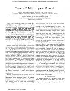
A. Uplink & Downlink Benefits Consider only the two user equipment UEs for simplicity served by large scaled MIMO BS as shown in Fig.1, (a). We assume the channel matrix h1 and h2 belongs to C N×1 having i.i.d entries with zero average value and unit variance. The h1 and h2 are completely known at the transmitter i-e channel state information is known at the transmitter (CSIT) and both h1 and h2 carries same energy. Then the output vector can be represented by (4). (4)
In order to detect the symbol of UE1, the BS can just use the Matched filter as in (5). N
h1Hy=x1 N ∑N hi1 2+ x2 ∑N hi1h + ∑N h1i ni N 2i N |
(5)
Using the huge number of antennas at the base stations BS i.e. N antennas at the transmitter, then the component of interference i-e and noise is eliminated and SNR can
(b) Downlink
Figure 1: Uplink and Downlink Channels with BS serving two UEs. (a) Channel matrix h1 and h2 for uplink. (b) h1H and h2H channel matrix for downlink.
From the previous discussion about uplink channel, the downlink benefits can be summed up as following: •
(3)
The ‘U’ is a precoding matrix responsible for power allocation to data symbols and is N×K dimension. The input vector x comprises data symbols with unit energy i.e. the energy E {||xk||2} =1, where k=1, 2, 3…… K, with K is the number of UEs that are served by BS of the massive MIMO [1]. Due to energy limit on ‘x’ and ‘z’, there is also energy check on precoding matrix ‘U’ such that Tr (UHU) = 1, and the Tr (.) is Trace operator. The massive MIMO systems benefits can be well explained if categorized as uplink and downlink channel benefits.
y = h1x1 + h2x2 + n
(a) Uplink
(2)
• •
The interference and noise will be removed when the number of antennas at the transmitter will be very large i-e N → ∞. If scaling down the power for each UE, then the maximum ratio transmission, MRT is the optimal techniques. If the number of antenna is comparatively small, then using the Zero-Forcing, ZF can achieve the significant performance [4].
III.
MASSIVE MIMO SPECTRL EFFICIENCY
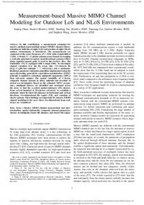
The evolution of wireless message has increased by an element of approximately forty in the past four to five years. One of the latest equipment that ensured to meet the requirement is massive MIMO system. It ensured energy and spectral improvement over 4G technologies. The large number of antennas used in massive MIMO system possibly antennas in hundreds or in multiple of hundred, they are positioned at the base station to achieve directional transmission from each single antenna. Transmission requirements from such antenna need simple multiplexing precoding and decoding techniques. Also, the system hardware need very simple components like low power amplifiers in place of high power linear 40 watt amplifiers. The resource allocation and power control actions may appears to be simple because of large number of antennas and the beam width for unit antenna is also improved. Fig.2, shows the graph between spectral efficiency and energy efficiency using massive MIMO system deployed with antennas, multiple of hundreds at BS
160 Ergodic capacity vs SNR 140 NT= 4 & NR=2 NT= 4 & NR=4
120
NT= 8 & NR=4 NT= 8 & NR=8
bps/Hz
100
NT= 100 & NR=20 NT= 200 & NR=20
80
NT= 300 & NR=20 60
Figure 4: (a) Distributed antenna design with Omni directional power distribution (b) Directional antenna pattern with directional main power lobe.
40
20
0
0
2
4
6 SNR[dB]
8
10
12
Figure 2: Spectral efficiency improvement usingg large antenna arrays.
It is clear from the above results thhat if a large array of antennas is used at the base station, it i has huge impact on the capacity and spectral efficiency of o the channel. IV.
MASSIVE MIMO DEPLOYMEN NT SCHEMES
Following are some of the deploym ment scenarios for massive MIMO systems that in futuree can be used for achieving high throughput. Fig.2, shoows some of the possible deployments schemes for massive MIMO systems that can be used in near futture to get large spectral efficiency in wireless communiication.
To the author’s best know wledge, for massive MIMO system deployment, both the antennas a arrangements are useful. As the numbers of anteennas are large in massive MIMO, the concentrated antennnas arrangement is more economical as every antenna will w transmit its directional sharp lobe and more directioonal power can propagate over large distance within the same s or different cells [5]. V.
PRECODIN NG SCHEMES
The main difficulty in dataa transmission in downlink is the complex detection techhnique used at receiver in large scaled multi user MIMO. M So, interference cancellation at the BS is reqquired. In this work Dirty Paper Coding (DPC), Block Diagonalization (BD) and Tomlinson-Harashima precodinng (THP) are compared. The early removal of interfeerence can be a supportive mode of attaining high data ratee only when the transmitter has information regarding thee interference on receiver side and is recognized as Dirrty Paper Coding Scheme DPC [6].The DPC capacity cann be given by (6) as if two users are kept below our designn [1]. CDPC =max log2det (1+ ρH ρ HPH),
(6)
P1, P2
P is a diagonal matrix witth P1 and P2 on its main diagonals. Using DPC the sum m of P1 and P2 must be unity. The precoding matrix is represented by U. The decomposition of U matrix cann be given by (7). U= Figure 3: Possible pictures for future massive m MIMO BS configurations.
The possible distributions used in future f large scaled antenna systems are going to be diistributed antenna system and concentrated antennaa system. The concentrated antenna design system will w transmit power more in some specified direction as compared to the distributed antennas systems Fig.4, shoows the two most types of the antennas configuration.
√ √
(7)
Where P a power distributiing matrix and w being an algorithm for precoding schem me and the normalization of power to 1 parameter is γ and γ can be given as in (8). γ= Tr (PWHW) as Tr (U ( HU) =1,
(8)
ZF precoding method abbolishes the intrusion by transmitting the signals towardds the proposed user with nulls in the γ “direction” of otther users [1]. The ZF precoder is given as (9) WZF=H†,
massive MIMO systems for higher throughput in the communication systems. Massive MIMO systems with antennas multiple of hundred positioned at the base station improves the spectral efficiency largely. The efficient deployment scheme for massive MIMO is the concentrated antenna design. Moreover, the DPC technique showed better performance when compared to BD and THP. Implementation of massive MIMO is essential for future wireless communication systems because of numerous applications of machine to machine, human to human, etc. ACKNOWLEDGMENT
Figure 5: Comparison between DPC, BD with ZF and THP.
Where H†= HH (HHH)-1 is the pseudo inverse of the channel matrix, then we can represent signal model by using the Zero-Forcing scheme as if we use the zero forcing precoding algorithms, then the output vector will be given as in (10). y=
x+n;
(10)
MMSE pre-coding can trade interference dominance against signal power effectiveness. The mathematical expression MMSE precoder is given by (11). WMMSE= HH (HHH + αI)-1
REFERENCES [1]
Linear pre-coding performance in measured verylarge MIMO channels BY Xiang Gao, Ove Edfors, Fredrik Rusek, and Fredrik TufvessonJ.
[2]
E. Dahlman, S. Parkvall, J. Sk¨ old, and P. Beming,3G Evolution HSPA and LTE for Mobile Broadband Academics Press, 2008.
[3]
Massive MIMO for Next Generation Wireless Systems, Erik G. Larsson, ISY, Linköping University, Sweden,
[email protected]
[4]
J. Hoydis, S. ten Brink, and M. Debbah, \Massive MIMO in the UL/DL of cellular networks: How many antennas do we need?" IEEE J. Sel. Areas Commun., vol. 31, no. 2, pp. 160-171, Feb. 2013.
[5]
H. Q. Ngo, E. G. Larsson, and T. L. Marzetta, “Energy and spectral efficiency of very large multiuser MIMO systems,” IEEE Trans. Commun., vol. 61, pp. 1436–1449, Apr. 2013.
[6]
A. Paulraj, R. Nabar, and D. Gore, Introduction to Space-Time Wireless Communications. UK: Cambridge University Press, 2003R
(11)
Where the new parameter ‘α’ can be given as α=K/ρ. If we keep small value of α, then MMSE precoder will reach the Zero Forcing precoder. Small value of α ensured the higher value for SNR for BD. The simulation results for DPC, BD with ZF and THP are shown by Fig.5,. Results depicted from Fig.5, showed the better performance of DPC over BD and THP. VI.
We are thankful to National University of Science & Technology Islamabad, Pakistan for supporting this research work financially. W. Afzal from MAJU Islamabad, F.Ahmad from University of Bremen Germany, U.Younas from COMSATS IIT Abbottabad and I. Mehmood from Brunel University London UK also made contributions.
CONCLUSION
Large scaled antenna systems have capabilities to fulfill the future needs of the wireless communication systems and also promised to give throughput even more than that of 4G systems. The author gave an idea to use