Figure 1 shows a conceptual design of the proposed sensor, LC6DMS. ... CCD measuring module is rigidly mounted onto machine slider. ... the geometric parameters of the sensor system and d is a distance of slider from the laser module. ... H x z. H y y. H L d z. H L x. L L. W y. L L. L L δ δ α Ï Î³ γ θ. â.....
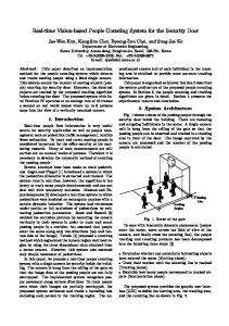
LASER-CCD BASED SENSOR SYSTEM FOR REAL TIME DETECTION OF MOTION LINEARITY Yoshihito Kagawa(1), Sadayuki Matsumiya(2), Kazuo Yamazaki(1), Yue Yang(1) (1): Department of Mechanical and Aeronautical Engineering, University of California, Davis CA 95616-5294 (2): Mitutoyo Corporation, Kawasaki, 213 –0012 Japan 1. Introduction The major goal of manufacturing science and technology is to achieve high productivity and high machining accuracy. In these days, while high productivity is being achieved, precision machining depends substantially on the reduction of motion errors induced by thermal and time dependent deformation. In order to minimize such an inaccurate machining results, the error compensation based on the in-process identification of the error cause is most effective. Currently, there are two methods used in error detection. The first one is based on the utilization of laser interferometric instrument [1]. By this method, error detection usually cannot be performed in a real-time fashion during the machining process. The second method is based on the pre-established relationship between temperature distribution and thermal deformation errors, such as thermal error model [2]. Although this approach has found some application in machine tool industry, the enhancement of accuracy is limited, since the thermal behavior and deformation of machine tool systems are highly nonlinear in machine conditions [3] and this method can only detect thermal errors. The purpose of this research is to propose and develop a novel Laser-CCD based 6 Degree-of -freedom motion Measuring System (LC6DMS) for real time, directly and simultaneously detection of motion linearity for machine error measurement and compensation. 2. A proposal of novel sensor system for real time detection of motion linearity 2.1 Conceptual design Figure 1 shows a conceptual design of the proposed sensor, LC6DMS. This sensor is composed of two main modules in addition to computer system, which are a laser module and a CCD measuring module. The laser model is stationery on the global coordinate system and the CCD measuring module is rigidly mounted onto machine slider. The laser module produces two laser beams, B1 and B2, by using two splitters, BS1 and BS2, as two metrology bases for measurement. A laser beam B2 has inclination angle γ against B1 to measure the linear motion in Z-axis of the slider. The CCD measuring module consists of three CCD cameras, CCD1, CCD2 and CCD3, and two beam splitters, BS3 and BS4. The 6 degree-of-freedom (DOF) erroneous motions of machine slider, which are 3 linear motions (δ x, δ y, d ) and 3 angular motions
(α , φ ,θ ) , are measured as the relative motion between B1 and BS3 at the lowercase coordinate
system o1B-x1By1Bz1B. During the measurement is being performed, the position of the laser beam is always captured by each CCD to measure the motion linearity of the machine slider. 2.2 Measurement principle Figure 2 shows the coordinate system of the proposed sensor system, LC6DMS. O-XYZ is a world coordinate system attached at the center of BS1 and the others are moving coordinate
systems attached at the center of BS3, BS4, CCD1, CCD2 and CCD3. W, H, L, L0 and γ are the geometric parameters of the sensor system and d is a distance of slider from the laser module. The kinematics relationship between a six-dimensional motion of the slider, a three-dimensional translation (δ x, δ y, d ) and a composite rotation (α , φ ,θ ) , and three laser positions
( y1C , z1C ) , ( y2C , z2C ) , ( x3C , y3C )
captured by three CCD cameras can be written in a
following equation (1). y1C z1C y2C = z2C x3C y3C − γ ( L + L0 )
0 −1 −1 0 0 −1 −1 0 −1 0 0 −1
δ x δ y d α φ θ
0 0 0 H+L 0 0 − ( H + L) 0 0 0 −( L + L0) W 0 0 γ L + L0 0 0 0 0
0 −H
H 0
(1)
The transformation equation from the three laser positions to a six-dimensional motion can be obtained by solving equation (1). Following equation (2) is the theoretical basis of LC6DMS for simultaneous measurement of 6 DOF machine slider motion. Once laser beam center coordinates are obtained from CCD image processing, the 6 DOF machine slide motion can be found immediately and simultaneously. H +L H z1C + z2C − L L H +L H y y − + 1C 2C δ x L L δ y L0 − H y − L + L0 − H y + 1 { y − γ ( L + L 0 )} 1C 2C 3C γL γ d γL = 1 1 α − y1C + y2C φ L L 1 1 θ z1C − Z 2C L L L0 − H L + L0 − H 1 z1C − z2C + x3C LW LW W
(2)
3. Design and simulation study of LC6DMS 3.1 Optimization of structural parameters In order to achieve highest measurement accuracy, the 5 structural parameters W, H, L, L0 and γ were optimized through simulation study. First, assuming a set of motion components, x1C
x1B φ(pitch) X 0
y1B
α(yaw)
y1C
θ(roll) o1B
H
CCD1
N3 Z
O
BS3
BS4
CCD3
φ δy
BS2
α
BS3
o1B d
W
γ
Slide motion d
BS2
o2B
γ
B2
x3C
CCD3
o3C
z3C
y3C L
Laser module
z2B
θ y2B
y1B
B2
BS4
N4 z1B
δx
B1
Y
B1
B4 x2B
x1B
X BS1
CCD2
BS1
Laser
CCD2
y2C o2C z2C
B3
z1B
Z
Y
x2C
CCD1 o1C z1C
L0
CCD measuring module
Figure 1: Conceptual design of LC6DMS
Figure 2: Coordinate system of LC6DMS
the theoretical beam center positions on each CCD are calculated by equation (1). Then, the beam center coordinate are obtained through calculation of intensity centroids of the beam images captured by each CCD in consideration of a diameter and divergence of a He-Ne laser beam and specifications of CCD cameras such as the count resolution and pixel size. Second, the 6 DOF erroneous motions are calculated by substituting the laser beam center coordinate obtained above into equation (2). The criteria of optimal design of the structural parameters are defined by following equation. δ xre =
d − dm δ xo − δ xm δ yo − δ ym × 100%, δ yre = × 100%, d re = o × 100% do δ xo δ yo
(3)
α − αm φ − φm θ −θm α re = o × 100%, φre = o × 100%, θ re = o × 100% αo ϕo θo
where subscripts o and m shows the given motion error initially and the measurement results obtained from simulation respectively. Figure 3 ~ Figure 6 shows the simulation results and its simulation parameters listed under the figures. The following structural parameters were designed based on these results and the overall module size requirement; L = 60mm, H = 54mm, W = 46mm, L 0 = 28.5mm, γ = 200arcsec (4) 3.2 Theoretical measurement accuracy The theoretical measurement accuracy of 6 DOF motion linearity was analyzed. Figure 7 and Figure 8 shows the theoretical measurement accuracy for linear motion. From Figure 7, it can be seen that the relative measurement errors for δ x and δ y are less than 0.09% over a range of 1~25 µm . Figure 8 shows that the relative error is less than 1.4% when the distance d is smaller than 2000 mm. The other theoretical measurement accuracy for three angular motions have achieved less than a 0.05% error over the range from 1 to 100 arecsec. 4. Conclusions (1) A laser-CCD based novel sensor system for the direct and simultaneous detection of 6 DOF motion linearity was proposed. α = 0.5 arc seconds α = 1 arc seconds α = 5 arc seconds α = 10 arc seconds
2
0.16
δx δx δx δx
0.14 0.12
Measuremement error δx re (%) Measurement error
Relative measurement error Measurement error
α re (%)
2.5
1.5
= = = =
0.5 µm 1 µm 5 µm 50 µm
0.1
0.08
1
0.06 0.04
0.5
0.02
0 0
10
20
30
40 L (mm)
50
60
70
Figure 3: Relationship between L and αre (d=100mm,δx=5µm,δy=5µm,φ=10arcsec, θ=15arcsec,H=50mm)
80
0
0
10
20
30
40 H (mm)
50
60
70
Figure 4: Relationship between H and δxre (d=100mm,δy=0.5µm,α=10arcsec,φ=10arcsec, θ=15arcsec,L=60mm)
80
(2) The theoretical bases of the proposed sensor system for simultaneous measurement of 6 DOF machine slider motions were established based on the kinematics relationships. (3) In order to achieve highest measurement accuracy, the key structural parameters were designed through simulation. (4) The theoretical measurement accuracy of the proposed sensor system was analyzed. References [1] Zhang, G., Wang, C., Hu, X., And Jing, F., Error Compensation Of Coordinate Measuring Machines. Annals Of The Cirp, 1985. 34(1): P. 445-448 [2] Chen, j.s., j. Yuan, and j. Ni, Thermal Error Modeling For Real-Time Error Compensation. International journal of advanced manufacturing technology, 1996b. 12(4): p. 266-275. [3] Attia, M.H.A.K., L., Nonlinear Thermoelastic Behavior Of Structural Joints--Solution To A Missing Link For Prediction Of Thermal Deformation Of Machine Tools. ASME Journal Of Engineering For Industry, 1979. 101: P. 348-354. 0.7
0.12
d = 0.5 mm d = 1 mm d = 5 mm d = 10 mm d = 50 mm
0.6
0.08
0.5
0.4
Measurement dreerror (%)
Measurement error (%) Measurement error θθrere (%)
0.1
5 mm 10 mm 15 mm 25 mm 30 mm
dre (%)
L0 = L0 = L0 = L0 = L0 =
0.06
0.3
0.04
0.2
0.02
0
0.1
0 0
10
20
30 W (mm)
40
50
60
50
100
150
200
250
300
γ (arcsec)
Figure 5: Relationship between θre and parameters W and L0 (d=100mm,δx=5µm,δy=0.5µm,α=10 arcsec, φ=10arcsec,θ=15arcsec,L=60mm,H=54mm)
Figure 6: Relationship between dre and beam inclination angle γ (δx=0.5µm,δy=0.1µm,α=10arcsec,φ=10arcsec, θ=15arcsec,L = 60mm,H=54mm,W=46mm, L0=28.5mm)
0.09
1.4
δx δy
0.08
δx δx δx δx
1.2 0.07
δy δy δy δy
= = = =
0.1 µm α = φ = θ = 0.1 arc seconds 1 µm α = φ = θ = 1 arc seconds 10 µm α = φ = θ = 10 arc seconds, 100 µm α = φ = θ = 100 arc seconds
1
dre (%)
0.06
= = = =
0.8
0.05
dre error (%) Measurement
δxre, δyre (%) Measurement error δxre, δyre (%)
0
0.04
0.6
0.03
0.4
0.02
0.2
0.01 0 0
5
10
15
20
25
δx, δy (µm)
Figure 7: Theoretical measurement accuracy of δx and δy (d=50mm, α=1arcsec, φ=5arcsec, θ=10arcsec)
0
0
200
400
600
800
1000 1200 d (mm)
1400
1600
Figure 8: Theoretical measurement accuracy of d
1800
2000