JLMN-Journal of Laser Micro/Nanoengineering Vol. 6, No. 1, 2011
Laser Processing by Using Diffractive Optical Laser Beam Shaping Technique Gediminas RAČIUKAITIS1, Evaldas STANKEVIČIUS1, Paulius GEČYS1, Mindaugas GEDVILAS1, Christian BISCHOFF2, Erwin JÄGER2, Udo UMHOFER2 and Friedemann VÖLKLEIN3 1
Center for Physical Sciences and Technology, Savanoriu Ave. 231, LT-02300 Vilnius, Lithuania E-mail:
[email protected] 2 TOPAG Lasertechnik GmbH, Nieder-Ramstaedter-Str. 247, D-64285 Darmstadt, Germany 3 Institut für Mikrotechnologien, Hochschule RheinMain, Am Brückenweg 26, D-65428 Rüsselsheim Laser beam shaping and homogenization techniques are substantial to optimize a large number of laser-material processing applications and laser-material interaction studies. Diffractive optical elements (DOE) play important role in provision of the process-adapted laser beam shaping. In this paper, we present an approach for laser beam shaping by using innovative DOE. The circular Gaussian beam was transformed to a square flat-top intensity profile in the focal plane of the objective lens by using novel DOE from TOPAG Lasertechnik GmbH. About 95% of the laser energy was coupled in the main beam with a nearly perfect rectangular shape. Experimental results have been achieved by applying the shaped beam for laser microfabrication. The picosecond and nanosecond lasers with moderate beam quality (M2=1.5) were used in the experiment. The shaped laser beam was applied for direct laser ablation of metal film on the glass substrate, drilling in a silicon wafer, scribing of thin-film solar cells and other technical materials. This technique allows creating a rectangular-shaped flat-top intensity profile in the focal plane that shows distinct advantages in laser material processing. DOI:10.2961/jlmn.2011.01.0009
Keywords: diffractive optics, beam shaper, laser processing, flat-top à
Multi-aperture beam integrators (homogenizers, microlens arrays, etc) [3]; à Field mapping transformation with refractive optics to get a uniformly distributed beam in the output plane, applicable to well-defined single mode laser beams [4]. Lossless transformations of the Gaussian beam to uniform irradiance use refractive, reflective or diffractive optics. Refractive and reflective optical elements of a special shape are arranged usually in beam expander geometry. More intensive central part of the beam is spread over a larger area, while weak wings of the lateral beam distribution are concentrated closer to the center. Considerations about description of flat-top profiles are given in [5]. Transforming the beam irradiance profile (Gaussian to more uniform) by retaining the wave-front shape requires 2 beam shaping elements [6]. Examples of laser beam shaping optics are: à refractive optical systems with at least two aspheric elements [7, 8]; à single bi-aspheric element [9]; à reflective optical systems [10]; à binary diffractive optics [11, 12, 13, 14, 15]; à 1D beam shaping with adjustable phase slit [16]. A laser beam shaper consisting of two aspheric lenses provides a fixed geometrical radial remapping of the optical power entering the input aperture to the output aperture. It must be mounted and aligned carefully in order to use it most efficiently [8]. The shaper requires that the angular misalignment be less than about 140 µrad with respect to
1. Introduction A Gaussian beam is a well-known and most convenient spatial laser beam distribution. It preserves its distribution when propagating and is excellent in focusing to a diffraction-limited spot. However, the spot area limited by a beam diameter (1/e2 level) contains only 86.5% of the laser beam power and intensity at the boundary is only 13.5% of the peak intensity. The energy in wings is lost or even causes several damage of surrounding material as well as a highintensity central peak. Because of threshold behavior of laser ablation the use of Gaussian beam profile is not favorable and most of laser material processing applications require uniform irradiation within a limited area with sharp edges on boundaries. This is especially true for thin–film structuring in electronics and photovoltaics, where high selectivity of the processing is top-most important. A uniform irradiance is further of interest for laser welding, laser micro-fabrication, laser radar, laser scanning and optical processing. The laser beam with uniform intensity distribution over the cross-section of the working plane is called a flat-top beam. The problem of shaping a laser beam arose nearly together with invention of a laser. Frieden published the first paper on shaping of the laser beam to one with uniform irradiance in 1965 [1]. Beam shaping can be implemented by integration (averaging) and deterministic transformation. There exist several laser beam shaping techniques: à Use of apertures when only the central flat portion of the beam is selected resulting in high energy losses [2]; 37
JLMN-Journal of Laser Micro/Nanoengineering Vol. 6, No. 1, 2011
the input beam, and translationally centered on the input beam to less than 25 µm. If the input laser beam has a poor profile, this will be echoed in the output beam profile. Only beams with a high quality (M2 < 1.10) can give acceptable output profile flatness. Flat-top intensity distribution can be realized through transformation of a single transverse mode Gaussian laser beam using an optical beam shaper. A low cost technique to fabricate the beam shaper that can convert a circular Gaussian beam into a circular flat-top beam was developed by [15]. The input beam size and laser wavelength should match its design specifications within 10% tolerances, and fine alignment between the input beam and the shaper within the 10 µm tolerance is required. Flat-top size is altered by changing focal length of the objective. In general, an accurate continuous surface profile is hard to achieve by etching process, leading to performance degradation of the fabricated flat-top beam shapers [17]. Complicated beam shaping systems can afford very high shaping efficiency (95% of energy in area of 90% intensity), however they require an ideal Gaussian beam and precise alignment. Sensitivity to misalignment and manufacturing inaccuracy can diminish and hide marginal improvement in performance from simple to advanced diffractive optics elements. Using simplified binary phase steps can greatly increase the beam shaper fabrication tolerance to low-cost flat-top beam shaper prototyping and production [15]. Processing, e.g. scribing thin films, with lasers with a circular Gaussian beam causes formation of non-smooth edges and damage or excess modification in overlapping areas [18, 19]. A flat-top square-shaped beam is proposed to be ideal for laser processing. Use of a square-shaped laser beam prevented cracking of the thin films in a-Si solar cells [20, 21]. A picosecond laser system with a special beam shaping optics was utilized for optimization of structuring processes of CIGS thin film solar cells [22]. Optimized top-hat optics with high straightness and steepness of the edges was developed using free-form refractive optics [23]. Processing results are demonstrated for various laser-based processes in thin film as well as crystalline Si solar cell production. The “free-shape” optics is difficult to fabricate [24] and that limits cost–effective application of the technology. New diffractive optics technique called Fundamental Beam-mode Shaping (FBS) was applied to transformation of a circular Gaussian beam at the input plane of FBS into rectangular beam with nearly flat-top (top-hat) distribution at the focal plane of the focusing objective. FBS represents kind of a phase plate with a continuous and smooth phase relief profile to transform a beam to one of sinc(x) -type in front of a focusing lens and which was realized by lithographic methods. The FBS-shaped beam was applied in laser microfabrication experiments using picosecond and nanosecond lasers with moderate beam quality (M2=1.5). The shaped laser beam was applied to direct laser ablation of metal film on the glass substrate, drilling in a silicon wafer, scribing of thin-film solar cells and other technical materials.
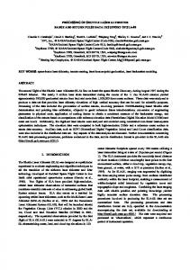
is focused by a lens, the intensity distribution in a focal plane of the lens remains circular Gaussian (Fig. 1). When a specially designed diffractive optical element for a flattop reshaping (FBS, for instance) is introduced in front of the lens, the intensity distribution in the focal plane can be transformed to a square-shaped beam (in lateral directions) with a flat-top intensity profile.
F
F FBS Fig. 1 Transformation of the beam profile by focusing with a lens without and with the FBS-type diffractive optical element in an optical path. Position of FBS along a beam path relative to the lens is not critical.
A diffractive optical element used in this research is a phase plate that converts the input Gaussian beam distribution into the top-hat beam after the objective lens. In the vicinity of the focal plane the beam forms spatial distribution with a flat-top and a square cross-section (Fig. 2). The FBS beam shaper represents kind of a phase plate with a continuous and smooth phase relief profile which was fabricated by lithographic methods.
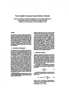
Fig. 2 Simulation of intensity distribution in a focal plane for a diffraction-limited Gaussian beam (a) and a beam trans-
2. Beam shaping technique The laser beam shaping is a process of redistributing the irradiance and phase. If a circular input Gaussian beam 38
JLMN-Journal of Laser Micro/Nanoengineering Vol. 6, No. 1, 2011
Fig. 3 Measured profile of the FBS shaped beam (a) and its cross-section (b): input Gaussian beam diameter (1/e2) 5.5 mm, wavelength 1064 nm, focusing lens F = 1000 mm.
formed to a square top-hat with the FBS shaper (b) with λ = 532 nm and NA = 0.011.
Efficiency of beam shaping from the circular Gaussian beam to the main top-hat profile is 95% in an area limited by 1/e2 (13.5%) level, and only 5% of energy is dissipated in wings. The flat-area uniformity of the top-hat profile is ± 2.5%. Characteristic of FBS is that the top-hat can be realized with a very small size that is near to the diffraction-limited spot. The minimum possible (top-hat) spot size is about 1.5-2 times that of the diffraction-limited Gaussian spot. Theoretically, steepness of the edges is diffraction-limited, but practically the limitations arose from quality of the objective and the initial beam (M2). Depth of the top-hat focus is close to that for a Gaussian beam. Size of the top-hat profile at 13% level (1/e2) can be adjusted by the focal lens and follows numerical aperture of the focusing objective according to equation [4]:
The characteristics and specific advantages of the FBS top-hat beam shaper are: à FBS beam shaper optics does not substitute the customer’s focusing system (objective) but works together with the existing optics. FBS is a single thin optical element, which can be installed somewhere in the optical path before the focusing lens (easy installation); à the flat-top beam profiles appear in the focal plane which simplifies the alignment of the optical setup; à the input beam needs to be of TEMoo Gaussian shape, however the FBS beam shapers accept beams even with M2=1.5, as shown experimentally below; à FBS shaper requires particular beam diameter, however, accepts a relatively high variation in the input beam diameter (+/- 5%). à as a single thin optical element with simple and symmetric design, it is insensitive to angular misalignment, compared to remapping system [7-10]; à the depth of focus for the flat-top beam is close to Rayleigh length of the Gaussian beam focused with the same lens.
4kλ F λ , (1) ⋅ ≈ π D NA where k is the empirical shaping parameter k~1.5; D is the diameter of the input beam on a lens; F is the focal length of the objective. Numerical aperture of the objective affects only size but not a shape of the top-hat profile. Specifications of the FBS beam shaper of TOPAG Lasertechnik GmbH are presented in Table 1. The shaper can be customized to transform an elliptical input beam. 2ωtop −hat =
Table 1
3. Experimental 3.1. Evaluation of the beam shapers Experimental setup (Fig. 4) included a nanosecond laser NL15100 (Ekspla Ltd) working at 1064 nm with the maximum output power of 15 W, attenuator made of λ/2 plate and thin-film polarizer P, a variable beam expander from Sill Optics to get the beam diameter of 3.8 mm (not shown in Fig.4), the FBS beam shaper, the focusing lens L with focal length of 500 mm, two 4o wedges W for reduction of the laser power and a CCD camera WinCamD with beam profile analyzing software (DataRay Inc). The laser was adjusted to generate a circular beam at pump level of 87%, which corresponded to the mean output power of 12 W @ 100 kHz repetition rate. The laser power was controlled by an external attenuator. When the laser power was above 2 W, neutral filters NF were installed in front of the CCD camera to prevent its overexposure.
Specifications of the FBS top-hat beam shaper.
Material Active area diameter Wavelength Transmission Shaping efficiency Uniformity Minimal lateral size of top-hat spot Installation
Fused silica 2.0, 2.5…10.0 mm 1064 nm, 532 nm, 355 nm or 266 nm (other on request) > 99% (with AR/AR coating) > 95 % (in top-hat spot) +/- 2.5% (of top-hat plateaus) square, ~ 1.5x of Gaussian spot In optics holder with x/y adjustment
A profile of the well-prepared (spatial filtering to achieve M2