Aug 22, 2008 - Latency Equalization: A Programmable Routing Service. Primitive. Minlan Yu. Princeton University. Marina Thottan. Bell Labs, Alcatel-Lucent.
Latency Equalization: A Programmable Routing Service Primitive Minlan Yu
Marina Thottan
Li Li
Princeton University
Bell Labs, Alcatel-Lucent
Bell Labs, Alcatel-Lucent
ABSTRACT
activities. The increased demand is placing an important requirement on the network infrastructure to be flexible and configurable to meet the myriad needs of network-based applications. The coexistence of many of these applications on the same network infrastructure requires innovative architectures that effectively utilize network resources. A key component of such flexibility is the programmable router. In this paper, using the concept of programmable router, we show the coexistence of two different routing architectures: one meets the low latency needs of conventional applications and the other meets latency equalization (LEQ) requirements among a group of interacting users. Until now most applications were content with a shortest path routing scheme that provides a low latency path through the network. With improvements in network transport technology and traffic engineering, meeting absolute latency requirements can be easily accomplished. However, online interactive applications require much more than absolute latency bounds. In online gaming, online distributed live music concerts, e-commerce and financial trading, the user experience is severely impacted by the latency differences experienced among the interacting users. In gaming the difference in lag experienced by gamers significantly reduces the entertainment value of the game [17]. Game servers have implemented mechanisms by which participating players can vote to exclude players with higher lag times. In distributed live music concerts [3], individual musicians are located at geographically different locations and the sound impairments introduced by delay differences among the musicians are perceptible to the human ear thus severely degrading the quality of the music. In e-commerce, latency differences between pairs of shopping agents and pricing agents can result in price oscillations leading to an unfair advantage to those pairs of agents whose latency difference is lower [11]. Conventional routing architectures are unable to meet the LEQ requirement and therefore applications typically perform latency compensation either at the client or the server [9, 2]. Latency compensation on the client side is based on hardware and software enhancements to speed up the processing of event updates and application rendering. These techniques cannot compensate for network-based delay differences among a group of players. Latency compensation by servers requires estimating the state of the network. This estimation has limitations since the state is inferred from application behaviors that are not always related to network issues [19]. Furthermore, the overhead of network measurements and the implementation of latency compensation techniques consumes significant processing power and CPU time on servers [6]. Typically there is a minimum memory and CPU power requirement on the game server that is associated with individual players. In some extreme circumstances, due to poor network support, servers are forced to spend expensive computation cycles on latency com-
Today the Internet is the primary medium for deploying new real time services such as gaming and distributed online live music concerts. Different network services have different expectations from the routing infrastructure. Some network services require conventional routing paths optimized for low latency or low congestion. However, real-time interactive services such as online gaming and distributed live music performance require more than just low latency. They require Latency EQualization (LEQ) among participating users. Although LEQ could be performed by the client or the server, end-system techniques for estimating network conditions are often inaccurate. Instead, we argue that the network should provide a LEQ service. We propose a LEQ routing architecture that can leverage programmable hub nodes. By deploying a few flexible, well-placed programmable nodes to redirect traffic, we can flexibly support both latency equalized and low latency routing services simultaneously. For LEQ routing, programmable hub nodes provide services such as application packet identification, application level packet processing and latency equalized routing paths. Extensive simulation studies on provider network topologies show that using just a few programmable nodes we can achieve an 80% improvement in LEQ over the conventional architecture that uses shortest path routing.
Categories and Subject Descriptors C.2.5 [Computer-Communication Networks]: Local and WideArea Networks; G.1.6 [Numerical Analysis]: Optimization
General Terms Algorithms; Design
Keywords Latency Equalization; Programmable Routing; Optimization; Online Interactive Applications
1. INTRODUCTION The increasing popularity and accessibility of the Internet has made it the new medium for many commercial and entertainment Permission to make digital or hard copies of all or part of this work for personal or classroom use is granted without fee provided that copies are not made or distributed for profit or commercial advantage and that copies bear this notice and the full citation on the first page. To copy otherwise, to republish, to post on servers or to redistribute to lists, requires prior specific permission and/or a fee. PRESTO’08, August 22, 2008, Seattle, Washington, USA. Copyright 2008 ACM 978-1-60558-181-1/08/08 ...$5.00.
39
pensation, that they are unable to scale for large numbers of users [6]. Without network support it is also difficult for applications to achieve robustness to transient network congestion and failures. Thus the ideal location for compensating delay imbalances in network paths of different users must reside in the network. We propose a latency equalization routing architecture that can be implemented on programmable network nodes to provide LEQ services. Using a few programmable hub nodes in the network we can steer packets through hub nodes along pre-determined paths, that compensate for the delay difference between the users. Hub nodes can also be used to steer packets away from congested links. The proposed LEQ routing architecture coexists and leverages the low latency routing architecture. Our LEQ routing architecture is validated through extensive simulation studies on ISP network topologies. We show that our routing scheme improves LEQ by 80% on average over the default shortest path routing. In summary, we make the following contributions in this paper: • LEQ routing architecture that can provide LEQ and reliable paths to users while maintaining the service experience of low latency users (maximum delay is bounded). To the best of our knowledge the proposed LEQ architecture using a greedy hub placement algorithm is the first theoretical result to optimize network routing for minimizing delay difference. • Deployment on a few flexible and well-placed programmable routers. Our LEQ routing architecture is incrementally deployable using a few well-placed programmable routers. LEQ services can be simultaneously supported with conventional low-latency routing protocols. The paper is organized as follows: Section 2 describes our LEQ routing architecture and deployment considerations on programmable routers. In Section 3, we formulate the hub placement problem and describe our greedy algorithm. We evaluate our hub routing architecture and algorithm in Section 4. Sections 5 and 6 discuss related work and conclude the paper.
2. LATENCY EQUALIZATION We first discuss possible alternate solutions for LEQ and their limitations. Next, we propose our LEQ routing architecture and its deployment on programmable routers.
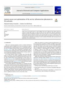
2.1 Alternative Solutions client1
R1
1 8 R4
4 4 R2 client2
server
R3
1
4 R6
R10
5 8
2 R5
3
R9
1
4
R7
4
8 3
R8
Figure 1: LEQ routing architecture Typical network providers usually use shortest path routing protocols (e.g. OSPF) as the intra-domain routing protocol. For example, in Figure 1, there are ten routers in the network domain. Client 1 and client 2 are connected to edge router R1 and R2 respectively. They both send packets to their server, which is connected to the edge router R10. The numbers on the links represent link weights. For simplicity, we assume that link weights are determined by the propagation latency on each link. Therefore the metric in OSPF is
40
assumed to be proportional to latency. In this way, we are able to find the minimum delay path for each client: packets from client 1 go through the path R1 → R3 → R9 → R10, which takes 3ms; packets from client 2 take the path R2 → R5 → R8 → R10, which takes 10ms. There is a 7ms delay difference between client 1 and client 2. Such delay differences are a significant problem for both servers and clients in real time interactive applications. The primary goal of routing protocols for most conventional applications is to send packets to their destinations through low-latency paths. Supporting multiple applications requiring LEQ and low latency routing at the same time is a challenging problem. One solution would be source routing, where each client edge router determines the paths for its own packets. Implementing LEQ using this approach will require a centralized server for global path computation and the collaboration of all client edge routers. This is computationally hard due to the diversity of available routes and also hard to implement since all routers in the network must identify application packets and support source routing. Our LEQ routing architecture ensures LEQ with only a small overhead and is scalable to many services with only minor modifications to the network infrastructure and routing strategy.
2.2
LEQ Routing Architecture
The basic philosophy behind LEQ based routing architecture is that we could choose longer paths for low latency clients (near the servers) by redirecting their packets through hub nodes. The hub nodes are strategically placed to ensure that the delay difference is minimized for those users that are steered via these hub nodes. This method is better than simply buffering packets at the server or within the router. Storing packets at the server is not scalable since the capacity of the server to support large number of users depends on the memory associated per user on that server. Also buffering in the network router is expensive due to power consumption/dissipation associated with high speed network hardware. In LEQ routing architecture, we define two types of edge routers: one that has clients connected to it which is called client edge router, and the other with servers connected to it which is referred to as server edge router. Any edge router can simultaneously be a client and a server edge router. The hub nodes can be enhanced routers or a stand-alone network appliance that have some network state that is pertinent to the application. In the LEQ architecture we assign each client to a set of hub routers, and then set up tunnels between each client and its associated set of hub nodes, and again from hub nodes to servers. Packets from clients are forced to go through the tunnels to their hub nodes. Hub routers then redirect the packets to the destined servers. For example, in Figure 1, R1 and R2 are client edge routers; R10 is server edge router. We choose R6 and R7 as hub nodes for R1, and set up tunnels of (R1, R6), (R1, R7), (R6, R10) and (R7, R10). Similarly, we choose R7 and R8 as hubs for R2 and set up corresponding tunnels. In this way, R1 has two paths to the server edge router R10: R1 → R6 → R10 and R1 → R7 → R10, both of which has the delay of 10ms. R2 also has two paths: R2 → R7 → R10 and R2 → R8 → R10, whose delay is 10ms. We achieve equalized latency by cleverly placing the hubs. Compared with OSPF routing, we use hubs R6 and R7 to redirect the packets from client 1 through a longer paths and thus find paths of equal delay with client 2. In the above example, we choose two hubs for each client. The main reason to choose multiple hubs for one client is that network delay consists of two parts: propagation delay and queuing delay. Under normal network conditions where the infrastructure is not fully utilized, our hub placement algorithm (Section 3) would provide equalized-latency paths in terms of propagation delay. With
the varying network conditions, we need multiple paths to ensure that packets always have an alternate path, and thus do not get bufferred on one path where queuing delay becomes a significant factor. In fact, there is a tradeoff to be made when the number of hubs for each client is increased. More hubs would lead to more diversity of LEQ paths for one client, and thus provide more reliable paths in the face of transient congestion or link/node failure. However, additional LEQ paths are realized by making a small compromise in the delay difference. We will show in Section 4.3 that 2 or 3 hubs for each client are enough to ensure both reliability and good delay difference.
during game play interactive packets requiring LEQ, would choose LEQ routing paths. The data plane of hub nodes can also apply application level packet processing (Figure 2 (4)). For online gaming, hub nodes can be used to aggregate event updates, and inspect packets to detect virus signatures. For distributed live concert, it may be used for sound amplification, echo cancellation, and distortion compensation. Hub nodes can also provide applications the opportunity to reconsider their packet destinations on the fly. For example in P2P games, hubs can perform load balancing among multiple servers for the clients. It can also aid in server migration by doing a soft hand-off between servers, where packets are sent to both the old and new servers till the migration process is complete. LEQ routing architecture is easy to be deploy on programmable routers for three reasons: i) It only requires a few programmable routers to participate in routing and thus reduces the cost of deployment; ii) It allows incremental deployment since even with one hub, we can reduce the delay difference by 41% on average (see Section 4.2); iii) No modification of the underlying routing protocols is necessary. The LEQ architecture can be implemented as an overlay on the substrate routers. The focus of this paper is to achieve LEQ routing using a programmable network architecture. For ease of discussion we only consider a single network domain, where both clients and servers are connected to the Internet through edge routers of the same ISP. Without loss of generality we assume that edge nodes aggregate application traffic from users that have similar access delays.
2.3 Deployment on Programmable Routers To apply LEQ routing, the edge router first identifies the application packets based on the port number and the IP addresses of the servers, which are known to the ISP in advance. Since we have multiple hub nodes for each client, for robustness the edge router then duplicates the application packets among pre-selected hub nodes and sends them through tunnels to the hub nodes. The hub nodes then redirect the packets to the destination edge router through tunnels. Conventional routers already support application identification and tunneling. We can also deploy these edge router functions using OpenFlow switch [13]. Programmable Router IPV4 IPV4
Control Plane (1) LEQ routing LEQ routing for gaming for gaming Quake 3 Car Racing
(2) FIB
FIB
(3) Packet Classifier Data Plane
IPV4
FIB
Packet Classifier
(4)
Tunnels
Packet Inspection etc.
LEQ routing LEQ routing for concert for trading
FIB
...
3.
FIB
Packet Classifier
HUB PLACEMENT ALGORITHM
We formulate the Hub Placement Problem, which focuses on how to select hub nodes in the network and the assignment of hubs to the client edge routers to minimize delay difference. We propose a greedy hub placement algorithm, which can achieve LEQ by using just a few programmable hub nodes in the network.
Packet Classifier
Echo Cancellation etc.
Tunnels
3.1
Figure 2: Programmable hub node
Problem Formulation
We use undirected graph G = (V, E) to represent the network. We denote d(u, v), u, v ∈ V as the propagation delay of the shortest path between routers u and v. We assume that the propagation delay is symmetric, i.e. d(u, v) = d(v, u). Let VP ⊆ V denote the set of client edge routers where users enter the network, VS ⊆ V denote the set of edge routers to which servers are connected, VH denote the set of routers that can be chosen as hub nodes. Without loss of generality, we represent all servers connected to the same server edge router as a single server. For simplicity in writing notation, we call server edge routers as servers, and client edge routers as clients respectively. For generality, we associate each client edge router with r servers that are nearest to it in terms of propagation delay. We denote by S pi the set of servers associated with client pi . S pi can be easily attained by calculating the propagation delay between clients and servers. We also define Dmax as the maximum delay each client pi can tolerate on its path to any server in S pi . We limit the total number of hubs to M and require each client has at least m hubs. Given M, m, r, Dmax , our goal is to find a set H pi of m hubs for each client pi , so that we can achieve the minimum delay difference. Delay difference δ is defined as:
The hub nodes are programmable routers placed at preselected locations. Figure 2 shows the architecture of such a programmable hub node. It consists of two parts – control plane and data plane. Based on the routing requirements of the applications, the control plane can be programmed to run different routing protocols in the virtual router environment (Figure 2 (1)). Each routing protocol then installs a specific forwarding table (Figure 2 (2)) that caters to the routing requirements of the application. For example, online games (e.g. Quake 3 and Car Racing) can each run an LEQ routing protocol with different latency equalization values. Since the gaming application uses the regular IPV4 routing for initial game set up, the FIB is composed from the output of both the LEQ route computations and the IPV4 route computation. In the data plane, a packet classifier is used to identify different packet types within a specific application and customized routing is applied to these packets(Figure 2 (3)). Packets from different applications are identified by the same source and destination IP address. Within an application, packets are classified based on port number or application tags. For example, packets in the game application can be classified into game setup packets and interactive event packets based on their tags. In the initial game set up when the player downloads a map from the gaming server, these packets can go through shortest path routing because they need faster download times and have no latency equalization requirement. However
δ= −
41
max
(d(pi , h j ) + d(h j , sk ))
min
(d(pi , h j ) + d(h j , sk ))
pi ∈VP ,h j ∈H pi ,sk ∈S pi pi ∈VP ,h j ∈H pi ,sk ∈H pi
with minimal δi . If there is more than one solution, we pick the one with smallest min delay among them.
Algorithm for min δ 1. Sort all the delays from client i to server j through hub h in increasing order, denote this array A 2. Binary search to find the min delay difference for each A[i]: for each delay A[i] le f t = Dmin , right=Dmax while(le f t not equal right) δi = (le f t + right)/2 Li = greedycover(A[i], δi , m, G, {d(u, v)}) if (|Li | > M) le f t = δi else right = δi 3. pick Li with smallest (δi ,A[i]) in terms of lexicographical order.
4.
4.1
s.t.
δ
∑ j∈VH
yj ≤ M
(1)
xi j ≤ y j , ∀pi ∈ VP , h j ∈ H ∑ j∈VH xi j ≥ m, ∀pi ∈ VP
(2)
di jk xi j ≤ Dmax , ∀pi ∈ VP , h j ∈ H pi , sk ∈ S pi
(4)
(3)
(di jk − di0 j0 k0 )(xi j + xi0 j0 − 1) ≤ δ ∀pi , p0i ∈ VP , h j , h0j ∈ H pi , sk , s0k ∈ S pi y j = {0, 1}, xi j = {0, 1}
Simulation Setup
For our network simulations we use large ISP network topologies, obtained through the Rocketfuel project [15]. In this paper, we show the evaluation result for Telstra network with 97 nodes and 132 links1 . For the dynamic case we consider the Abilene network topology [1]. Our evaluation uses several parameters that define the Hub routing architecture: the total number of hub nodes M, the number of hub nodes selected for each client m, the number of servers in the network NS , and the number of servers allocated for each client r. The performance metric is the delay difference δ, which means the maximum difference in delay among all the paths selected. We use all the edge nodes in the backbone topology as clients. We then run the hub routing and shortest path routing algorithms to compute paths for these clients and servers. Note that in the static case the path computation is based on the propagation delay in the network. The propagation delay is estimated based on the geographical distances between any two nodes. In the shortest path routing algorithm we associate the link weights with the propagation delay of these links. To eliminate the bias introduced by server location, we test all the possible locations of the servers; For interactive applications delay is not as critical as delay difference, as long as we bound the absolute delay with Dmax = 100ms [5].
Figure 3: The pseudo-code of hub placement algorithm The IP formulation for this problem is given as follows. min
EXPERIMENTAL EVALUATION
The performance of our LEQ routing architecture is evaluated by both static and dynamic analysis on provider network topologies. In the static case we only consider propagation delays. For the dynamic case we consider a rate varying traffic matrix where the offered load on the links could approach the maximum link capacity over short periods of time. The performance of the LEQ scheme is compared with that of OSPF.
(5) (6)
δ denotes the delay difference defined above. y j = 1 denotes router hi is a hub, 0 otherwise. xi j = 1 denotes router h j is a hub for client Pi , 0 otherwise. We use the short hand notation di jk for d(pi , h j ) + d(h j , sk ). Equation (1) is the constraint that the total number of hubs can not be more than M. Equation (2) means that each client can only select its hubs from the hub set. Equation (3) is the constraint that a client must have at least m hubs. Equation (4) is the constraint that the maximum delay can not be more than Dmax . Equation (5) specifies that pair-wise delay difference can not exceed δ. Equation (6) indicates that y j , xi j are binary variables. Note that Equation (4) takes effect only when xi j = 1 and xi0 j0 = 1, otherwise, the constraint is trivially true.
4.2
Static Analysis
Using the static traffic scenario we analyze the effect of propagation delay, and explore the potential of discovering LEQ paths. (1) Hub-routing achieves on average 80% improved LEQ as compared with shortest path routing. Figures 4, 5 show the average delay difference between all the client paths to any one server for both LEQ routing and OSPF. In both network topologies we find that LEQ routing with a single hub per client (m = 1) improves the LEQ (84% for Telstra and 90% for Abilene) over OSPF. Also the best performance for LEQ routing is achieved when the number of hubs per client (m) is set to 1. As the number of hubs per client increases we find that due to the increased path diversity the average delay difference increases. However, even with 3 hubs per client the performance of LEQ routing is significantly better than OSPF. We also experimented with multiple servers, and found that LEQ routing provides similar improvements in delay difference 2 . (2) Hub routing is incrementally deployable; A few hub nodes is sufficient to obtain LEQ paths. We calculate the delay difference improvement of LEQ routing over OSPF ∆:
3.2 Greedy Hub Placement Algorithm The optimal solution for the hub placement algorithm is hard even for a small network graph since the time complexity is exponential in the number of hub candidates. We have proved that the hub placement problem is NP-hard and it is hard to find good approximations. To solve the greedy hub placement problem we design a simple greedy heuristic algorithm to pick the M hubs. Given two solutions, i.e. two sets of M hubs, if the overall maximum delay difference is the same, we favor the one with smaller minimum delay. Our algorithm sorts the delay in increasing order. For each possible delay Ai , we set it to the minimum delay experienced by nodes in a solution. We use binary search to find a feasible solution with smallest maximum delay difference δi . In each step of the binary search, given a minimal delay A[i] and a maximum delay difference bound δi , we use a greedy set cover algorithm to pick the M hubs. That is, we pick one hub at a time; the selected hub “covers” (connect clients and servers through the hub) the maximum number of uncovered client edge routers. If m > 1, each client edge router has to cover m times. The pseudo-code of the algorithm is illustrated in Figure 3. Dmin denotes the minimal delay difference among all paths from client i to server j through hub h. Recall that Dmax denotes the maximum tolerated delay difference. We pick the solution
∆=
δOS PF − δhub δOS PF
(7)
We see that in all topologies, even with one hub, LEQ routing gains at least 22% (41% on average) improvement in delay difference. 1 2
42
The results of other networks are omitted due to page limitations This result is omitted due to page limitations
Delay Difference (ms)
25 20 15 10
35
50
30
OSPF LEQ routing (m = 1) LEQ routing (m = 2) LEQ routing (m = 3)
40 30 20
2
4 6 Number of Hubs (M)
8
10
0 0
OSPF (max delay) OSPF (avg delay) OSPF (median delay) LEQ routing (max delay) LEQ routing (avg delay) LEQ routing (median delay)
25 20 15 10
10
5 0 0
60
Delay (ms)
OSPF LEQ routing (m = 1) LEQ routing (m = 2) LEQ routing (m = 3)
Delay Difference (ms)
30
5
2
4 6 8 Number of Hubs (M)
0 0
10
2
4
8
6
10
Number of Hubs (M)
Figure 4: Delay difference of Telstra net- Figure 5: Delay difference of Abilene net- Figure 6: Average and max delay of Telwork work stra network (m = 3, NS = 1) When the number of hubs is above 5, we are able to achieve up to 90% improvement. We also note that in all topologies increasing the total number of hub nodes in the network to more than 5 does not provide any significant improvement in the delay difference measurements. This suggests that even with varied topologies (Telstra with 97 nodes and Abilene with 11 nodes) LEQ routing architecture only requires a few hub nodes to be placed in the network. Since traffic requiring LEQ is only a small percentage of the total network traffic, a few hub nodes are sufficient to obtain latency equalized paths. (3) We trade the delays of clients with shorter paths with the overall delay difference of the applications. The simulation study shows that LEQ among multiple clients is best achieved through the LEQ routing architecture. Figure 6 provides a clear understanding of how this is accomplished. It shows the maximum, average and median delay of the selected paths for both OSPF and LEQ routing with number of hubs per client set to 3 in the Telstra network. We see that LEQ routing achieves smaller delay difference at the expense of increasing the average delay of shorter paths in the network. However, the maximum delay among these paths is similar to that obtained with OSPF. The increase in average delay mainly comes from the increase in latency of the shorter paths. Delay is not as critical as delay difference, as long as we bound the absolute delay with Dmax = 100ms [5]. This observation highlights the philosophy behind LEQ routing: storing packets on network paths rather than buffering them at the end points reduces the delay difference between the clients.
the address of the destination node and sends them to a hub node. The hub node is selected in a round robin schedule from among the m hubs allocated to the client through the hub placement algorithm. Upon receiving the probing packets, the hub node looks up the destination server from the packet and redirects it to the destination node. For comparative purposes, we also send probing packets through shortest path routes computed using Dijkstra’s algorithm with the delay metric. For the dynamic analysis we use the Abilene network topology. The delay metric is obtained using the propagation delays on each of the links. We use a single server that is located at Washington D.C. All the 11 edge nodes have clients. The bandwidth capacity of each link in Abilene is fixed at 10 Mbps. Background traffic model: We generate real background traffic matrices by analyzing packet traces of Abilene Netflow data [1] and scale them down by 1000 times, to fit with our 10Mbps link capacity, since Abilene bandwidth is 10Gbps. Additional traffic is added to the link between Denver and Kansas City thus progressively creating a bottleneck at this link. The size of the probing packet is 48 bytes, which is similar to the size of general UDP packets in gaming applications [10].
Delay Difference (ms)
400
4.3 Dynamic Analysis In this section we show that even under dynamic traffic conditions with queuing as a critical factor, LEQ routing achieves much smaller delay differences than OSPF. In a typical service provider network, links are usually maintained at below 50% utilization. However it has been observed that in the presence of bursty or long range dependent traffic, it is possible that in certain time scales the average utilization could be close to 90% - 95% of the link capacity. Simulation model: We implemented LEQ routing as a new application in ns-2 for packet-level simulations. In this application, we have two classes of packets: packets of background traffic and probing packets. The background traffic denotes traffic of all the other applications in the network. Since traffic requiring LEQ is much smaller than background traffic and will not influence the network conditions, we do not simulate them explicitly in our experiment. Instead, we use small probing packets that go through hub routing paths and measure the actual latency experienced by these packets. To force some of the probing packets to go through hub routing paths, each client node marks the probing packets with
300
OSPF LEQ routing (m = 1) LEQ routing (m = 2) LEQ routing (m = 3)
200
100
0 5
6
7
8
9
10
11
12
13
14
15
Amount of Traffic on the Hot Spot Link (Mbps)
Figure 7: Abilene network: Single bottleneck link Simulation result: Figure 7 shows the real time evolution of the delay difference of hub routing and shortest path routing with increasing load on the hot spot link between Denver and Kansas City. When the amount of traffic on this link approaches the capacity of the link, both OSPF and LEQ routing with m = 1 experiences significant queuing delay. Using LEQ routing with m = 2, or 3 we maintain the delay difference due to path diversity. When the amount of traffic continues to increase, packets from different clients are also influenced by this heavy traffic, and thus the delay difference among all the clients decreases in both cases: OSPF and LEQ routing with m = 1. From this study we show that with 2 or
43
among participating users. This paper proposes a LEQ routing architecture, which uses a few flexible, well-placed programmable routers to redirect application traffic. Our evaluation shows that with the simple addition of a few programmable hub nodes it is possible to achieve LEQ routing and support low latency routing service at the same time. These programmable hub nodes can also provide application packet identification, application level packet processing and application customized routing. The main features of the proposed programmable LEQ-routing architecture is the configurable deflection of packets at the edge nodes and the flexible control and packet handling at the intermediate nodes. These features will help service providers to easily define new network services, enable incremental deployment and reduce the time to market of new services. It is also a cost effective solution for trial deployments since the services are being configured over the same physical substrate network.
3 hubs per client, LEQ routing can get around transient congestion in the network and reduce the corresponding queuing delay.
5. RELATED WORK There are several architectures that are being proposed to build programmable routers [16], [14], [7]. A common theme in all these architectures is the separation of the control and forwarding plane. The implication of this separation from the perspective of defining new routing services is that within the switch architecture it is possible to allocate computing resources to implement application specific routing protocols and packet processing. Thus it is possible to place both the conventional low latency routing and the LEQ routing service in the same physical infrastructure. Furthermore through virtualization of the data plane we can identify and separate packets from different services and subject them to customized packet processing. The availability of flexible network architectures will usher in the era of application customized networks such as networks for online gaming and online distributed live music concerts. Network support for such real time services is a relatively new topic since the scalability of these services has only recently become a significant issue. In [6] the authors provide the motivation for network support and design a game booster box that is a network-based game platform. The goal of the booster box is to off load network functions such as monitoring from the game server. In most real time applications there are two important service metrics: an upper bound on the maximum latency that can be tolerated and the latency difference between the interacting users of the service. Maximum latency bound can be attained by the conventional routing architecture. However the requirement of equalizing latency among a group of users is more challenging. In [18] Zander et al. show that fairness in multi-player games is affected by the delay difference between players and propose a scheme by which the delay corresponding to the largest latency player is estimated and the application tries to even up every client’s experienced RTT by adding flow-specific additional latency to each active game flow. In this approach there is a significant overhead of measuring flowspecific delays. In [3] the authors show that for online distributed live music concerts, despite significant enhancements to the hardware and software of end-systems, the inconsistencies in network delay perceptibly affects the quality of the music. The authors suggest that impairments from network delay can only be addressed by influencing packet routing in the network. Using the LEQ routing architecture the application network can be customized to use LEQ paths as the default routing strategy. Such an approach will provide more predictability to the delay variance and also will not require any flow specific monitoring. To the best of our knowledge, LEQ has not been studied from a purely network perspective. Also there are no known theoretical results aimed at optimizing latency difference in the network, nor are there any routing architectures that have been proposed to solve the latency equalization problem. Previous work focused on reducing delay in the overlay network (e.g. RON [4]), or reduce bandwidth cost with bounded delay (e.g. VPN tree routing [12]). The proposed LEQ-routing architecture involves the optimal placement of hub nodes to achieve LEQ paths in the network. Previously Cha et al. [8] proposed placing relay nodes in the intra-domain network, but their algorithm aimed at reducing cost, not the delay difference.
7.
REFERENCES
[1] http://abilene.internet2.edu/. [2] A. Abdelkhalek and A. Bilas. Parallelization and performance of interactive multiplayer game servers. 2004. [3] A.Kapur, G. Wang, P. Davidson, and P. R. Cook. Interactive network media: A dream worth dreaming? In Organized Sound, 2005. [4] D. G. Andersen, H. Balakrishnan, F. Kaashoek, and R. Morris. Resilient overlay networks. In Proc. Symposium on Operating Systems Principles, Banff, Canada, 2001. [5] G. Armitage. An experimental estimation of latency sensitivity in multiplayer quake 3. In Proceedings of the International Conference on Networks, 2003. [6] D. Bauer, S. Rooney, and P. Scotton. Network infrastructure for massively distributed games. In ACM NetGames, 2002. [7] S. Bhatia, M. Motiwala, W. Muhlbauer, V. Valancius, A. Bavier, N. Feamster, L. Peterson, and J. Rexford. Hosting virtual networks on commodity hardware. Technical Report GT-CS-07-10, Georgia Tech, 2007. [8] M. Cha, S. Moon, C.-D. Park, and A. Shaikh. Placing relay nodes for intra-domain path diversity. Proc. IEEE INFOCOM, 2006. [9] C. Diot and L. Gautier. A distributed architecture for multiplayer interactive applications on the internet. IEEE Network Magazine, 1999. [10] J. Farber. Network game traffic modelling. In ACM NetGames, 2002. [11] A. Greenwald, J. Kephart, and G. Tesauro. Strategic pricebot dynamics. First ACM Conference on E-Commerce, 1999. [12] A. Gupta, J. Kleinberg, A. Kumar, R. Rastogi, and B. Yener. Provisioning a virtual private network: A network design problem for multicommodity flow. In Proc. ACM Symposium on Theory of Computing, 2001. [13] N. McKeown, T. Anderson, H. Balakrishnan, G. Parulkar, L. Peterson, J. Rexford, S. Shenker, and J. Turner. OpenFlow: Enabling innovation in campus networks. In Computer Communication Review, 2008. [14] R. Ramjee, F. Ansari, M. Havemann, T. V. Lakshman, T. Nandagopal, K. K. Sabnani, and T. Y. C. Woo. Separating control software from routers. COMSWARE, 2006. [15] N. Spring, R. Mahajan, and D. Wetherall. Measuring ISP topologies with Rocketfuel. Proc. ACM SIGCOMM, August 2002. [16] J. Turner. A proposed architecture for the GENI backbone platform. In ACM ANCS, 2006. [17] S. Zander and G. Armitage. Empirically measuring the QoS sensitivity of interactive online game players. Australasian Telecommunication Networks and Applications Conference (ATNAC), December 2004. [18] S. Zander, I. Leeder, and G. J. Armitage. Achieving fairness in multiplayer network games through automated latency balancing. Advances in Computer Entertainment Technology, 2005. [19] H. Zhang. The effect of delay on network games. Master’s thesis, Computing Science, UMEA University, Sweden, 2006.
6. CONCLUSION Real time applications such as online gaming and online live distributed music performance require Latency EQualization (LEQ)
44