Hindawi Security and Communication Networks Volume 2018, Article ID 4529652, 10 pages https://doi.org/10.1155/2018/4529652
Research Article Latent Fingerprint Segmentation Based on Ridge Density and Orientation Consistency Manhua Liu
,1,2 Shuxin Liu
,3 and Weiwu Yan
4
1
Department of Instrument Science and Engineering, School of EIEE, Shanghai Jiao Tong University, Shanghai 200240, China Shanghai Engineering Research Center for Intelligent Diagnosis and Treatment Instrument, School of EIEE, Shanghai Jiao Tong University, Shanghai 200240, China 3 School of Educational Science, Minnan Normal University, Zhangzhou, Fujian 363000, China 4 Department of Automation, School of EIEE, Shanghai Jiao Tong University, Shanghai 200240, China 2
Correspondence should be addressed to Shuxin Liu;
[email protected] and Weiwu Yan;
[email protected] Received 29 September 2017; Accepted 12 March 2018; Published 17 May 2018 Academic Editor: Eryun Liu Copyright © 2018 Manhua Liu et al. This is an open access article distributed under the Creative Commons Attribution License, which permits unrestricted use, distribution, and reproduction in any medium, provided the original work is properly cited. Latent fingerprints are captured from the fingerprint impressions left unintentionally at the surfaces of the crime scene. They are often used as an important evidence to identify criminals in law enforcement agencies. Different from the widely used plain and rolled fingerprints, the latent fingerprints are usually of poor quality consisting of complex background with a lot of nonfingerprint patterns and various noises. Latent fingerprint segmentation is an important image processing step to separate fingerprint foreground from background for more accurate and efficient feature extraction and matching. Traditional methods are usually based on the local features such as gray scale variance and gradients, which are sensitive to noise and cannot work well for latent images. This paper proposes a latent fingerprint segmentation method based on combination of ridge density and orientation consistency, which are global and local features of fingerprints, respectively. First, a texture image is obtained by decomposition of latent image with a total variation model. Second, we propose to detect the ridge segments from the texture image, and then compute the density of ridge segments and ridge orientation consistency to characterize the global and local fingerprint patterns. Finally, fingerprint segmentation is performed by combining the ridge density and orientation consistency for latent images. The proposed method has been evaluated on NIST SD27 latent fingerprint database. Experimental results and comparison demonstrate the promising performance of the proposed method.
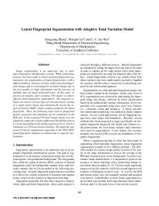
1. Introduction Latent fingerprints are the finger skin impressions, which are unintentionally left on the surface of a crime scene by deposits of oils and/or perspiration from the finger [1]. This impression is usually invisible to the naked eye but it can be captured with some special techniques. Latent fingerprints have been used as an important evidence to identify criminals in law enforcement agencies for more than a century. Different from the plain and rolled fingerprints which are captured with good quality in the controlled environment and widely used in commercial area, latent fingerprints are usually of low image quality caused by unclear ridge structure, uneven image contrast, and various overlapping nonfingerprint patterns like lines, printed letters, handwritings, etc. as shown in Figure 1. Samples of rolled, plain, and latent fingerprint
images are shown in Figures 1(a), 1(b), and 1(c), respectively. Due to the poor quality, the performance of automated latent fingerprint identification system (AFIS) (matching latent fingerprint to full template fingerprints) is much lower than that of matching full to full fingerprints [1]. Thus, it is necessary to perform the segmentation and enhancement processes for latent fingerprints before input to AFIS. However, the latent fingerprints are usually corrupted by noise and the valid fingerprint area is small like Figure 1(c). These problems cause the difficulties in segmenting the fingerprint ridge area from the latent image. Fingerprint segmentation is an important processing step to segment the fingerprint foreground with the interleaved ridge and valley structure from the complex background with nonfingerprint patterns for more accurate and efficient feature extraction and identification. There are many methods
2
Security and Communication Networks
(a)
(b)
(c)
Figure 1: Three types of fingerprints: (a) plain, (b) rolled, and (c) latent.
proposed for fingerprint segmentation in the literature [5–8]. In these methods, the fingerprint image is uniformly divided into blocks and some local image features such as mean and variance of gray values and the orientation consistency are extracted to evaluate the fingerprint quality for segmentation. They can work well for plain and rolled fingerprints, but their performances are not satisfactory for latent fingerprints. The main difficulties may be due to weak ridge structure, and the complex overlapping irrelevant patterns and various types of noise in latent fingerprint images. The valid fingerprint region is small compared to the complex background. Thus, it is still challenging for segmentation of latent fingerprints. There are some research efforts made to investigate new methods for improving the latent fingerprint segmentation [2–4, 9–15]. Zhang et al. [2] proposed an adaptive directional total variation (ADTV) model for latent fingerprint segmentation. This model combines both the anisotropic directional TV term and the spatially adaptive fidelity weight for more effective segmentation of latent fingerprint. Short et al. [9] proposed a method to apply an adaptable ridge template to determine a goodness of the fit score in a local region of fingerprint for segmentation. Choi et al. [10] proposed to combine both ridge orientation and frequency features for latent fingerprint segmentation. In that method, the orientation tensor is used to obtain the symmetric patterns of fingerprint ridge orientation and the local ridge frequency is estimated by the local Fourier analysis. These two features are combined for segmentation. Karimi-Ashtiani and Jay Kuo [11] proposed a latent fingerprint segmentation algorithm based on a quasi-global fingerprint model, which did not rely on the local gradients for estimation of orientations and frequencies and thus is robust to the gradient deviations. Cao et al. [12] proposed a method for latent fingerprint segmentation based on a ridge quality measure which was defined as the structural similarity between the fingerprint patch and its dictionary based reconstruction. A learning based method was proposed for latent fingerprint image segmentation based on fractal dimension features and weighted extreme learning machine ensemble [3]. The fractal dimension features were computed to characterize the texture patterns of image
patches and persistent in geometric quantities. Instead of using the local image features, the linear density, which is a global feature, was computed by detection of line segments for latent fingerprint segmentation [4]. A clustering-based approach was investigated for latent fingerprints segmentation [13]. A latent fingerprint segmentation method was proposed based on orientation and frequency features [14]. Recently, a deep artificial neural network (DANN) model was proposed for segmentation of latent fingerprints by using a stack of restricted Boltzmann machines (RBMs) to learn the features of fingerprint image patches [15]. This paper proposes a latent fingerprint segmentation method based on combination of the ridge density and orientation consistency, which are extracted to characterize both the global and local texture patterns of fingerprint image. First, a total variation (TV) model is used to decompose the latent image into texture and cartoon components. The cartoon component is removed as the noise while the texture component consisting of the fingerprint pattern is used for further processing. Second, to characterize the interleaved ridge and valley structure of fingerprint, we propose to detect the ridge segments and then compute the ridge density and orientation consistency to evaluate the quality of fingerprint image. Finally, a segmentation mask is generated by thresholding and morphological processing for each latent image. The proposed method is tested on NIST SD27 latent fingerprint database and is compared to some existing methods to demonstrate its performance. The rest of this paper is organized as follows. In Section 2, we will present the proposed latent fingerprint segmentation algorithm in detail. Section 3 provides the experimental results and comparisons. Finally, Section 4 concludes this paper.
2. The Proposed Method In this section, we present the proposed segmentation algorithm for latent fingerprints in detail. The valid fingerprint pattern is often characterized as a number of parallel
Security and Communication Networks
3
Figure 2: The flowchart of the proposed latent fingerprint segmentation algorithm.
(a)
(b)
(c)
Figure 3: (a) A latent fingerprint image and its TV decomposed components: (b) cartoon and (c) texture.
interleaved ridge and valley flows, while the nonfingerprint pattern consists of arch, lines, printed letters, speckle, handwritings, stain, and other noises. The main difference between the fingerprint and nonfingerprint patterns is the parallel interleaved ridge and valley flows. Thus, we propose to detect the ridge segments and the region with the dense distribution of parallel ridge segments is segmented as the foreground of fingerprint image. The general flowchart of the proposed latent fingerprint segmentation algorithm is demonstrated in Figure 2. It consists of four main steps, i.e., decomposition of
latent image into cartoon and texture components, detection of ridge segments, computation of ridge density and orientation consistency, and latent fingerprint segmentation, which will be presented in the following subsections, accordingly. 2.1. Decomposition of Latent Fingerprint. In addition to the fingerprint pattern, latent images often contain various types of nonfingerprint patterns such as arch, line, character, speckle, handwritings, and stain, which usually have the smooth inner surface and sharp edges (see Figure 3(a)).
4
Security and Communication Networks
(a)
(b)
(c)
Figure 4: (a) Binary image with noise removal, (b) the reversed binary image with noise removal, and (c) the final detected ridge segment points.
The total variation (TV) model was proved to be an efficient model for regularizing images without smoothing the boundaries of targets [16]. To reduce these structured noises for latent fingerprint segmentation, the TV model is used to decompose the latent image 𝑦 into texture and cartoon components, i.e., 𝑦 = 𝑢 + V. Texture component V contains the oscillatory and noise component, while cartoon 𝑢 consists of the piecewise smooth component. Mathematically, the decomposition is obtained by minimization of total variation [16]: min
(𝑢,V)∈𝐿2 (Ω)
2 {TV (𝑢) + 𝜆 𝑢 − 𝑦2 } ,
(1)
where 𝑢 and V denote the image cartoon and texture components, respectively; TV(𝑢) denotes the total variation of 𝑢; and ‖ ⋅ ‖2 is a two norm. The parameter 𝜆 ∈ [0, 1] is used to balance the tradeoff between the fidelity of 𝑢 and the minimization of TV. Small 𝜆 will produce weak texture and strong cartoon image and vice versa. In our experiments, 𝜆 is set to 0.4 to decompose the texture component of latent image for fingerprint segmentation. Figures 3(b) and 3(c) show the decomposed cartoon and texture components of the latent image shown in Figure 3(a), respectively. The cartoon component consists of most nonfingerprint patterns and is removed as noise while the texture image contains the weak fingerprint pattern. After decomposition, not only the structure noise but also the varying illuminations have been significantly reduced from the texture image, which will facilitate latent fingerprint segmentation. 2.2. Detection of Ridge Segments. After image decomposition by TV model, a texture image is obtained and used for further processing while the cartoon image with most of the structured noises is removed as nonfingerprint pattern. It will be easier to extract features from the texture image for fingerprint segmentation. The texture component of latent fingerprint is characterized by oscillatory patterns with interleaved and parallel ridge and valley structure. In this work, we propose to detect the ridge segments from the
texture image to capture the fingerprint patterns. The ridge segment detection procedure can be divided into image binarization with noise removal, image thinning, and orientation computation for each ridge point, detailed as follows. First, the texture image is a gray scale image of [0, 255] which is thresholded to a binary image with noise removal. For simplicity, the threshold is set to 128. In the binary image, the black points are the background pixels while the white points are the candidate points of ridge segments. Since the latent fingerprint is often corrupted by various types of noise, it is necessary to remove the noisy points from the binary image for more reliable detection of ridge segments. The noisy points usually occur as the isolated points and are removed according to the following formula: {0, { { { { { 0, { { { { 𝐼 (𝑖, 𝑗) = {0, { { { { { 0, { { { { {1,
𝐼 (𝑖 − 1, 𝑗) + 𝐼 (𝑖 + 1, 𝑗) = 0 𝐼 (𝑖, 𝑗 − 1) + 𝐼 (𝑖, 𝑗 + 1) = 0 𝐼 (𝑖 − 1, 𝑗 − 1) + 𝐼 (𝑖 + 1, 𝑗 + 1) = 0
(2)
𝐼 (𝑖 + 1, 𝑗 − 1) + 𝐼 (𝑖 − 1, 𝑗 + 1) = 0 elsewise.
Figure 4(a) shows the binary image after removing the noisy points from the thresholded binary image of texture image in Figure 3(c). In addition, to enhance the detection of ridge segments, we also reverse the thresholded binary image with the black points changed into white points and vice versa. The noisy points are removed with the same procedure as above. These two binary images with noise removal are generated for better characterization of the interleaved ridge and valley pattern. Figure 4(b) shows the reversed binary image after removing the noisy points. Second, the above two binary images are thinned with the thinning method in [17] and these two thinned images are superimposed into one binary image to form ridge segment points. However, there are some noisy ridge segment points, which are usually characterized to be short, closed, and crossed. To remove the noisy ridge points for reliable detection of ridge segments, we delete the short ridge segments
Security and Communication Networks
5
(a)
(b)
(c)
Figure 5: (a) The ridge density map, (b) orientation consistency map, and (c) the final image quality map.
with the length smaller than 4 and delete the closed ridge circles with the number of end points less than 2. For each ridge point, we compute the number of ridge points in its 3 × 3 neighborhood. If it is larger than 3, the point is the crossed point, and this point and all the ridge segment points in its 3 × 3 neighborhood are changed to black points. In this way, we go through all ridge points and obtain a set of connected and continuous ridge segments, which are denoted as {𝑟1 , 𝑟2 , . . . , 𝑟𝑛 }. Figure 4(c) shows the final detected ridge segment points from Figure 4(b). Finally, we compute the orientation for each ridge point. Each ridge segment is composed of a set of connected points. Thus, the orientation of each ridge point is computed based on its neighboring connected ridge points. Assume that the ridge segment 𝑟𝑘 consists of 𝑚 connected points, denoted as {𝑝𝑘0 , 𝑝𝑘1 , . . . , 𝑝𝑘𝑚 }, where 𝑝𝑘0 , 𝑝𝑘𝑘 , and 𝑝𝑘𝑚 are the starting, middle, and ending points of the ridge segment 𝑟𝑘 , respectively. The orientation of point 𝑝𝑘𝑘 is computed as follows:
𝜃𝑝𝑘𝑘
(𝑦𝑝𝑘𝑘+3 − 𝑦𝑝𝑘𝑘 ) { { { ), 𝑘 + 3 ≤ 𝑚 arctan ( { { { (𝑥𝑝𝑘𝑘+3 − 𝑥𝑝𝑘𝑘 ) ={ { (𝑦𝑝𝑘𝑚 − 𝑦𝑝𝑘𝑚−3 ) { { { ) , 𝑘 + 3 > 𝑚, {arctan ( (𝑥𝑝𝑘𝑚 − 𝑥𝑝𝑘𝑚−3 ) {
(3)
where (𝑥𝑝𝑘𝑘 , 𝑦𝑝𝑘𝑘 ) is the coordinates of point 𝑝𝑘𝑘 . Thus, we have obtained both the location and orientation for each ridge segment point of the binary image. 2.3. Computation of Ridge Density and Orientation Consistency. From Figure 4(c), we can see that the valid fingerprint area should have more parallel ridge segments than the nonfingerprint area. Thus, after detection of the ridge segments and computation of the orientation for each ridge point, we propose to compute a ridge density measure, which evaluates how densely the ridge points are distributed in a local region with the specific orientation. In addition to the locations, the orientations of ridge points are also considered because the neighboring ridge segments are parallel. Thus, the whole orientation range [0 𝜋) is equally divided into 9 bins as {𝛽1 , 𝛽2 , . . . , 𝛽9 }, i.e., 𝛽1 ∈ [0, 𝜋/9), 𝛽2 ∈ [𝜋/9, 2𝜋/9), . . . , 𝛽9 ∈
[8𝜋/9, 𝜋). To compute the ridge density, we divide the binary image with the ridge segment points into the blocks of 16 × 16 pixels. Let 𝑆𝑟 denote the total number of ridge points in each block and 𝑆𝑟𝛽𝑘 (𝑘 = 1, 2, . . . , 9) denote the number of ridge points in each block with the orientation in the bin 𝛽𝑘 . The interleaved ridge and valley flows of fingerprint change smoothly except for a few singular points. Thus the ridge points are densely distributed in a local fingerprint region with consistent orientations. The ridge density for block (𝑖, 𝑗) is computed by sum of the weighted distribution of the ridge points with respect to different orientations as follows: 9
Rd (𝑖, 𝑗) = ∑ ( 𝑘=1
𝑆𝑟𝛽𝑘 𝑆𝛽𝑘 ) × ( 𝑟 ), 𝑆 𝑆𝑟
(4)
where 𝑆 is the area of the block. The ridge density Rd(𝑖, 𝑗) is high if the ridge points are densely distributed in a block and concentrated in one orientation bin. Otherwise, the ridge density is low. In addition, the orientations of ridge segments usually change slowly in a local neighborhood. The orientation of each block is defined as the orientation with the maximum number of ridge points. We compute the orientation consistency to evaluate how consistent the orientation of each block is with its 8 neighboring orientations in the 3 × 3 neighborhood. The orientation consistency for block (𝑖, 𝑗) is computed as Cons (𝑖, 𝑗) =
∑1𝑚=−1 ∑1𝑛=−1 𝑤𝑖+𝑚,𝑗+𝑛 cos (𝜃𝑖+𝑚,𝑗+𝑛 − 𝜃𝑖,𝑗 ) − 1 ∑1𝑚=−1
∑1𝑛=−1
𝑤𝑖+𝑚,𝑗+𝑛
,
(5)
where 𝑤𝑖+𝑚,𝑗+𝑛 ∈ {0, 1} denotes the availability of orientation 𝜃𝑖+𝑚,𝑗+𝑛 of block (𝑖 + 𝑚, 𝑗 + 𝑛) and Cons(𝑖, 𝑗) ∈ [0, 1]. If the block orientation is consistent with its 8 neighboring orientations, Cons(𝑖, 𝑗) is close to 1. Figures 5(a) and 5(b) show the ridge density map and the orientation consistency map of Figure 4(c), respectively. 2.4. Latent Fingerprint Segmentation. For latent fingerprint segmentation, the ridge density and orientation consistency
6
Security and Communication Networks
(a)
(b)
(c)
(d)
Figure 6: Fingerprint segmentation results by (a) thresholding, (b) the biggest mask, (c) the convex hull, and (d) the final segmentation result overlapped with texture image.
are combined to generate an image quality measure, which is computed for each block as 𝑄 (𝑖, 𝑗) = Rd (𝑖, 𝑗) × Cons (𝑖, 𝑗) .
(6)
Figure 5(c) shows the image quality map of Figure 4(c). Thresholding is applied to generate a binary segmentation mask for each fingerprint. To fill the gaps and eliminate the islands, morphological operations are further applied to obtain the biggest and continuous binary mask. The convex hull of the biggest mask is computed as the final segmentation mask. Figures 6(a), 6(b), 6(c), and 6(d) show the fingerprint segmentation results by thresholding, the biggest mask, its convex hull, and the final mask overlapped with the texture image, respectively.
3. Experimental Results In this section, we conduct experiments on the NIST SD27 latent fingerprint database to test the performances of the proposed algorithm. NIST SD27 consists of 258 latent fingerprints which are manually assigned into three different levels of qualities: “good”, “bad”, and “ugly” [18]. The numbers of “good”, “bad”, and “ugly” fingerprints are 88, 85, and 85, respectively. Our algorithm was implemented with MATLAB software on a computer of 3.1 GHz Intel Core i5-4440, 4 G RAM, and 64-bit Windows OS. For the latent fingerprint images in NIST SD 27, the average computation time of our algorithm is about 5 seconds for one image. The manual markups of ROI (Region of Interest) by experts provided in [19] are used as the ground truths for NIST SD 27 in our experiments. We compare the segmentation results of the proposed algorithm with the manual markups and other published methods [2–4, 10]. First, we test the proposed algorithm on the same sample latent fingerprints of different image qualities from NIST SD27 database as those in [3]. The segmentation results provided in [3] are directly used for comparison. The segmentation results of the method [2] are downloaded from the author’s website. Figures 7, 8, and 9 show the comparisons of the segmentation results by the manual markups, the method [2], the method [3], and the proposed method, for good, bad, and ugly latent fingerprint images, respectively. From these
Table 1: Comparison of the segmentation accuracies in different methods. Methods Method [2] Method [10] Method [3] Method [4] Proposed method
MDR% 14.10 14.78 9.22 13.32 13.03
FDR% 26.13 47.99 18.7 24.21 23.17
Average% 20.12 31.38 13.96 18.76 18.13
results, we can see that the method [2] usually generated a larger segmentation mask which includes the nonfingerprint patterns. There are some gaps and islands in the segmentation results by the method [3]. Our proposed method can perform well to separate the fingerprint foreground from the complex background for latent images of different qualities, which is closer to the manual markups. Second, although the segmentation results of latent images can be evaluated visually, we compare the segmentation accuracy of our method with those of some published methods [2–4, 10]. Two measures, the Missed Detection Rate (MDR) and the False Detection Rate (FDR), are computed for performance comparison on NIST SD27. The manual segmentation masks are used as the ground truth. MDR is the average percentage of foreground pixels misclassified as background, while FDR is the average percentage of background pixels misclassified as foreground. Table 1 shows the comparison of the segmentation accuracy in the proposed method with those of the existing methods [2–4, 10]. The segmentation results are directly used from those reported in the paper. In the comparison, the computations of MDR and FDR and the ground truth of segmentation masks by the proposed method are same as those in [2, 4, 10]. The MDR and FDR of our method are 13.03% and 23.17%, respectively. These results show the effectiveness of our segmentation method compared to the other methods. It seems that the method [3] performed best in comparison. But it should be noted that the segmentation ground truth in method [3] was generated by the author of the paper and is different from our proposed method and the computations of MDR and FDR measures were based on image patches instead of pixels.
Security and Communication Networks
(a)
7
(b)
(d)
(c)
(e)
(f)
Figure 7: (a) Good latent fingerprint image, (b) the texture image, (c) manual marked ROI, and the segmentation results (d) by method [2], method [3], and our proposed algorithm.
(a)
(b)
(c)
(d)
(e)
(f)
Figure 8: (a) Bad latent fingerprint image, (b) the texture image, (c) manual marked ROI, and the segmentation results (d) by method [2], method [3], and our proposed algorithm.
8
Security and Communication Networks
(a)
(b)
(c)
(d)
(e)
(f)
Figure 9: (a) Ugly latent fingerprint image, (b) the texture image, (c) manual marked ROI, and the segmentation results (d) by method [2], method [3], and our proposed algorithm.
The ultimate goal of segmentation is to improve the performance of latent fingerprint identification. Thus we conduct the latent fingerprint identification experiments to test the effectiveness of the proposed segmentation algorithm finally. The foreground of segmented texture image is the input of latent image matching. The commercial software VeriFinger SDK 6.5 is integrated to perform the feature extraction and matching for latent fingerprint identification. To make the latent matching experiment more realistic and challenging, the template database includes both the 258 template fingerprints of NIST SD27 and the 27,000 fingerprints of NIST SD14. Each latent fingerprint is matched against all the fingerprints of template database and a matching score is generated between the latent and a template fingerprint. The matching scores are sorted in descending order and the identification performance is evaluated by Cumulative Match Characteristic (CMC) curve. A CMC curve plots the identification accuracy rates with respect to different rank-k (𝑘 = 1, 2, . . . , 20). We compare the performances of the proposed algorithm with those of the linear density based method [4] and the manual markup as well as those without segmentation, which are denoted as “linear density based method”, “proposed method”, “manual markup”, and “without segmentation”, respectively. “Without segmentation” means the texture image is directly used as input for latent fingerprint identification. Figures 10(a), 10(b), 10(c), and 10(d) show the
comparisons of CMC curves on all latent, “good”, “bad”, and “ugly” quality fingerprints of NIST SD27, respectively. We can see that the identification of latent fingerprints with segmentation can achieve much better performance than that without segmentation for all latent fingerprints. For bad latent images, the proposed algorithm performs better than the linear density based method [4] and even better than the manual markup. The performance is just slightly worse than the manual markup for latent fingerprints of good quality. For all fingerprints, the proposed algorithm has better performance than the linear density based method [4] and achieves comparable performance to the manual markup. These results and comparison demonstrate the effectiveness of the proposed segmentation algorithm for latent fingerprints.
4. Conclusion This paper proposes a latent fingerprint segmentation algorithm based on combination of ridge density and orientation consistency. First, a texture image is generated by image decomposition with a TV model, and the structured noise and illumination variation is greatly reduced from the texture image. Second, we propose to detect the ridge segments and compute the ridge density and orientation consistency, which are combined for latent fingerprint segmentation. Finally, the proposed algorithm is tested on NIST SD27 and compared
Security and Communication Networks
9
(a)
(b)
(c)
(d)
Figure 10: Comparisons of CMC curves by the proposed method, the linear density based method [4] and the manual markup as well as texture image without segmentation for (a) all, (b) good, (c) bad, and (d) ugly latent fingerprints of NIST SD27.
with other methods and the manual markups. Experimental results and comparisons demonstrate the effectiveness of the proposed segmentation algorithm for latent fingerprints.
Conflicts of Interest There are no conflicts of interest related to this paper.
Acknowledgments This work was supported in part by National Natural Science Foundation of China (NSFC) under Grants nos. 61773263 and 61375112 and The National Key Research and Development Program of China (no. 2016YFC0100903), SMC Excellent Young Faculty program of SJTU. This work was also supported in part by Science and Technology of Fujian Education Department under Grant no. JAT170365.
References [1] A. K. Jain and J. Feng, “Latent fingerprint matching,” IEEE Transactions on Pattern Analysis and Machine Intelligence, vol. 33, no. 1, pp. 88–100, 2011. [2] J. Zhang, R. Lai, and C.-C. Jay Kuo, “Adaptive directional total-variation model for latent fingerprint segmentation,” IEEE Transactions on Information Forensics and Security, vol. 8, no. 8, pp. 1261–1273, 2013. [3] J. Ezeobiejesi and B. Bhanu, “Latent Fingerprint Image Segmentation Using Fractal Dimension Features and Weighted Extreme Learning Machine Ensemble,” in Proceedings of the 29th IEEE Conference on Computer Vision and Pattern Recognition Workshops, CVPRW 2016, pp. 214–222, 2016. [4] S. Liu, M. Liu, and Z. Yang, “Latent fingerprint segmentation based on linear density,” in Proceedings of the 9th IAPR International Conference on Biometrics, ICB 2016, 2016.
10 [5] M. U. Akram, S. Nasir, A. Tariq, I. Zafar, and W. Siddique Khan, “Improved fingerprint image segmentation using new modified gradient based technique,” in Proceedings of the 2008 Canadian Conference on Electrical and Computer Engineering - CCECE’08, pp. 001967–001972, Niagara Falls, Canada, 2008. [6] X. Dai, J. Liang, Q. Zhao, and F. Liu, “Fingerprint Segmentation via Convolutional Neural Networks,” in Biometric Recognition, vol. 10568 of Lecture Notes in Computer Science, pp. 324–333, Springer International Publishing, 2017. [7] A. M. Bazen and S. H. Gerez, “Segmentation of fingerprint images,” in Proceedings of 12th Annual Workshop Circuits, Systems and Signal Processing, 2001. [8] J. Ma, X. Jing, Y. Zhang, S. Sun, and H. Huang, “Simple effective fingerprint segmentation algorithm for low quality images,” in Proceedings of the 2010 3rd IEEE International Conference on Broadband Network and Multimedia Technology, IC-BNMT2010, pp. 855–859, 2010. [9] N. Short, M. Hsiao, A. Abbott, and E. Fox, “Latent fingerprint segmentation using ridge template correlation,” in Proceedings of the 4th International Conference on Imaging for Crime Detection and Prevention 2011 (ICDP 2011), pp. P28–P28, London, UK. [10] H. Choi, M. Boaventura, I. A. G. Boaventura, and A. K. Jain, “Automatic segmentation of latent fingerprints,” in Proceedings of the 2012 IEEE 5th International Conference on Biometrics: Theory, Applications and Systems, BTAS 2012, pp. 303–310, usa, September 2012. [11] S. Karimi-Ashtiani and C.-C. Jay Kuo, “A robust technique for latent fingerprint image segmentation and enhancement,” in Proceedings of the 2008 IEEE International Conference on Image Processing, ICIP 2008, pp. 1492–1495, usa, October 2008. [12] K. Cao, E. Liu, and A. K. Jain, “Segmentation and enhancement of latent fingerprints: a coarse to fine ridge structure dictionary,” IEEE Transactions on Pattern Analysis and Machine Intelligence, vol. 36, no. 9, pp. 1847–1859, 2014. [13] I. Arshad, G. Raja, and A. K. Khan, “Latent Fingerprints Segmentation: Feasibility of Using Clustering-Based Automated Approach,” Arabian Journal for Science and Engineering, vol. 39, no. 11, pp. 7933–7944, 2014. [14] T. Revathy, G. Pramila, A. Adhiraja, and A. Askerunisa, “Automatic Latent Fingerprint Segmentation based on Orientation and Frequency Features,” in Proceedings of the 3rd International Conference on Communication and Signal Processing, ICCSP 2014, pp. 1192–1196, 2014. [15] J. Ezeobiejesi and B. Bhanu, “Latent fingerprint image segmentation using deep neural network,” Advances in Computer Vision and Pattern Recognition, vol. 1, pp. 83–107, 2017. [16] A. Buades, T. M. Le, J.-M. Morel, and L. A. Vese, “Fast cartoon + texture image filters,” IEEE Transactions on Image Processing, vol. 19, no. 8, pp. 1978–1986, 2010. [17] L. Lam and C. Y. Suen, “Thinning methodologies—a comprehensive survey,” IEEE Transactions on Pattern Analysis and Machine Intelligence, vol. 14, no. 9, pp. 869–885, 1992. [18] NIST Special Database 27, “Fingerprint Minutiae from Latent and Matching Ten-print Images,” http://www.nist.gov/ srd/nistsd27.htm. [19] J. Feng, J. Zhou, and A. K. Jain, “Orientation field estimation for latent fingerprint enhancement,” IEEE Transactions on Pattern Analysis and Machine Intelligence, vol. 35, no. 4, pp. 925–940, 2013.
Security and Communication Networks
International Journal of
Advances in
Rotating Machinery
Engineering Journal of
Hindawi www.hindawi.com
Volume 2018
The Scientific World Journal Hindawi Publishing Corporation http://www.hindawi.com www.hindawi.com
Volume 2018 2013
Multimedia
Journal of
Sensors Hindawi www.hindawi.com
Volume 2018
Hindawi www.hindawi.com
Volume 2018
Hindawi www.hindawi.com
Volume 2018
Journal of
Control Science and Engineering
Advances in
Civil Engineering Hindawi www.hindawi.com
Hindawi www.hindawi.com
Volume 2018
Volume 2018
Submit your manuscripts at www.hindawi.com Journal of
Journal of
Electrical and Computer Engineering
Robotics Hindawi www.hindawi.com
Hindawi www.hindawi.com
Volume 2018
Volume 2018
VLSI Design Advances in OptoElectronics International Journal of
Navigation and Observation Hindawi www.hindawi.com
Volume 2018
Hindawi www.hindawi.com
Hindawi www.hindawi.com
Chemical Engineering Hindawi www.hindawi.com
Volume 2018
Volume 2018
Active and Passive Electronic Components
Antennas and Propagation Hindawi www.hindawi.com
Aerospace Engineering
Hindawi www.hindawi.com
Volume 2018
Hindawi www.hindawi.com
Volume 2018
Volume 2018
International Journal of
International Journal of
International Journal of
Modelling & Simulation in Engineering
Volume 2018
Hindawi www.hindawi.com
Volume 2018
Shock and Vibration Hindawi www.hindawi.com
Volume 2018
Advances in
Acoustics and Vibration Hindawi www.hindawi.com
Volume 2018