Robert E. Cohen, Gareth H. McKinley, Mehmet Toner, Michael F. Rubner, Brian L. Wardle. ABSTRACT. Here, we demonstrate layer-by-layer (LbL) assembly o
Layer-by-layer functionalized nanotube microfluidic platform for biodetection
arrays:
A
versatile
Allison L. Yost, Setareh Shasavari, Grinia M. Bradwell, Roberta Polak, Fabio Fachin, Robert E. Cohen, Gareth H. McKinley, Mehmet Toner, Michael F. Rubner, Brian L. Wardle ABSTRACT Here, we demonstrate layer-by-layer (LbL) assembly of polyelectrolyte multilayers (PEM) on three-dimensional nanofiber scaffolds. High porosity (99%) aligned carbon nanotube (CNT) arrays are photolithographically patterned into elements that act as textured scaffolds for the creation of functionally-coated (nano)porous materials. Nanometer-scale bilayers of Poly(allylamine hydrochloride)/Poly(styrene sulfonate) are formed conformally on the individual nanotubes by repeated deposition from aqueous solution in microfluidic channels. Computational and experimental results demonstrate that the LbL deposition is dominated by diffusive transport of the polymeric constituents, and we use this understanding to demonstrate spatial tailoring on the patterned nanoporous elements. A proof-ofprinciple application, microfluidic bioparticle capture using NHS-biotin binding for isolation of prostate specific antigen (PSA), is demonstrated. -----------------------------------------------------------------------------------------------------------The ability to achieve nanoscale control of interfaces and surfaces has fueled new ideas and technologies in a myriad of applications, including the design of various microelectronic [1-3], energy storage [4-7], optical [8-11], and biomedical devices [12-15]. In particular, biomedical research has benefited from advances in nanoscale surface chemistry and surface manipulation, enabling applications from controllable adsorption/release of proteins to affinity chromatography to drug delivery [16-18]. The vast majority of surface tailoring however, has been demonstrated on readily accessible planar or particle surfaces and the transition to more complex 3D porous materials, particularly space-constrained nanoporous materials, is currently limited. Thus, what is clearly needed to produce the next generation of biomedical devices, is the ability to systematically functionalize the surfaces of 3D nanotemplates contained within complex geometries with conformal nanoscale coatings of any desired chemistry and surface morphology. The conformality of the resultant coating and its precise nanoscale thickness control is critical to maintaining the advantages and functionality provided by the original 3D nanoscale template. A promising nanostructuring approach to create 3D templates is the use of textured nanoporous elements as a scaffold for surface functionalization and as building blocks for various devices. One such textured element that has received considerable attention is an aligned array of nanofibers, such as carbon nanotubes
(CNTs) [19, 20, 21]. CNTs are attractive due to their intrinsic mechanical, electrical, magnetic, and optical properties [22-29], as well as the multiple routes to synthesize and give texture to bulk assemblies of the nanofibers. Biomedical applications are particularly well suited due to the wealth of existing surface chemistries available for functionalization (e.g., antibody binding). As such, one can apply nanoscale control over chemical composition, spatial morphology, and the interfaces of materials to create versatile, materials-driven platform technologies that can be targeted to a wide range of applications. For example, by exploiting the porosity (99%) of CNT arrays, vertically aligned carbon nanotube (VACNT) forests can be successfully integrated into a variety of devices [30, 31] including within microfluidic devices, allowing separation and specific targeting of biomolecules ranging from sizes of 40nm-10μm with an enhanced capture efficiency of 7x [32, 33]. Due to their size and high surface area, CNTs provide unique accessibility to bioparticles in a high throughput fashion at scales currently difficult to achieve through MEMs at such rates, such as biomarker proteins, viruses, exosomes, or cellfree DNA in blood or other bodily fluids for diagnostics applications. Although in principle, various approaches exist for modifying the surfaces of carbon nanotubes contained within CNT arrays, the layer-by-layer (LbL) assembly approach [34] holds the most promise for fulfilling the multiple requirements of nanoscale thickness and morphology control, conformal coating ability and the ability to create a wide range of different surface chemistries and functionalities. Indeed, the greatest advantage of the LbL assembly process compared to other coating processes continues to be its ability to produce nanoscale conformal coatings from an extremely wide variety of organic, inorganic and biological molecules and materials [35-38]. Excellent examples of these capabilities as applied to biomaterial based devices and constructs including sensors [39] and drug delivery elements [40, 41] abound in the literature. Relevant to this work is the idea that LbL assembly can be readily carried out within the confines of complex nanoscale geometries and within functional microfluidic devices [42]. In the former case, LbL assembly has been demonstrated within nanochannels and nanopores [42-46]. In the latter case, LbL assembled coatings have been used for the development of microfluidic based in vitro assays or for studying fundamental cell and tissue biology. For example, Sung et al. modified PDMS surfaces using LbL coatings to reduce non-specific binding and for enhanced detection of low levels of protein [47]. Others have designed a microfluidic platform with LbL coatings for identifying the dengue virus using an ELISA approach. Results indicated that LbL coatings on channel surfaces improved stability and efficiency, reducing surface modification time twelve-fold [48]. Alternatively, LbL modified microfluidic systems have been used to control the flow or flow constituents within the device. Kirchof et al., for example, utilized LbL coatings in microfluidic devices to generate pH gradients that promote cell migration [49], while Barker et al. used them to alter surface charge and control the direction of electroosmotic flow [50]. Our approach has been to utilize LbL coatings as a means to systematically functionalize patterned carbon nanotube arrays contained within microfluidic
devices designed to filter, capture and detect low levels of biological markers for disease [32,33]. We demonstrate that it is possible to control the LbL assembly pattern within a microfluidic device by only varying the height of the microchannel. In this manner, we can coat and functionalize individual carbon nanotubes throughout the entire CNT array or just cover the outer surface of the array. In the former case, conformal coatings on individual nanotubes have been achieved within arrays with tube-to-tube spacings of about 80 nm. This level of functionalization control can be used to take full advantage of the highly porous nature of the CNT arrays, as well their ability to controllably capture and release biomarkers of various types. To demonstrate this, we have used this technology to functionalize the CNT surfaces with antibodies and capture prostate specific antigen (PSA) as an exemplary capture target. A significant challenge in microfluidic platform bioparticle isolation is to achieve sufficient interaction between the target biomolecule and the functional surfaces to promote binding. This work provides a powerful tool to functionally tailor and grade nanomaterials in 3 dimensions, enabling the design of devices that enhance bioparticle-surface interaction. Additionally, due to the nature of the spacing between individual CNTs (~80 nm), this platform specifically has high potential in isolation of nano-sized bioparticles, such as viruses, exosomes, or DNA. The microfluidic chip design and assembling processes (Fig 1) were developed to favor adsorption and LbL conformal coating on the nanoporous CNT elements contained within the microfluidic device (Fig 1a). Patterned CNT elements were grown via chemical vapor deposition (CVD) on Si wafers. These porous VACNT forests consist of arrays of multi-walled CNTs (OD 7.78 +/- 0.85 nm, ID 5.12 nm +/0.76 nm, spaced ~80 nm apart, # walls 5 +/- 1, 1 vol%, 1.59 g/cm^3 [51, 52]) (Fig. 1b,c) patterned using photolithography into macroscopic elements that have high porosity (~99%) and accessibility to aqueous solutions. For this study, one geometric pattern of CNTs was used for simplicity: a single pillar with 1mm diameter (consisting of more than 10଼ individual carbon nanutubes) centered in the 3 mm wide, 7 mm long microfluidic channel (Fig 1b, c). CNT pillar heights averaged 50 µm tall, but ranged between 30-80 µm. Results were also obtained with other element geometries (not shown), such as an array of pillars or a “wall”, i.e. rectangular feature perpendicular to flow. In fact, for particle isolation, a wall device, which acts like a filter, would be an ideal design; however, the resulting pressure drop can damage the adhesion of the CNTs to the substrate. Therefore, the geometric design involves the trade-off between the maximum allowed pressure and maximum interception of flow streamlines with the CNT elements. Photolithography permits numerous patterns to be designed in the future for further investigation of an optimized CNT element geometry.
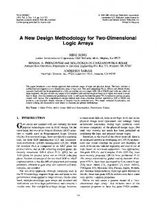
a
Outlet
c
b
Polymer 2 [-] CNT element
Polymer 1 [+]
Water
Silicon Substrate
d
20 um
e
f
1 um
3.5 LbL bilayers
LbL Coating
60 220
CNT
Z(um) 0 220
Y (um) X (um)
Flow
0 20 nm
Figure 1: Schematic and characterization of LbL coating on nanoporous CNT element (a) Illustration of microfluidic chip design featuring pillar (D = 1 mm) CNT element in microfluidic channel (3 mm wide)(b) SEM images of an as-grown aligned CNT pillar element (c) High resolution SEM of CNT element exhibiting textured porosity (d) 3D reconstruction of confocal z-slices (PAH-Fluor, 488 nm) of a 220 μm x 220 μm section of CNT pillar element, demonstrating polymer coating through z plane. (e) TEM micrograph of individual CNT coated with 3.5 bilayers of PAH-Fluor/SPS assembled at pH 9.3. Dashed black line outlines CNT diameter, and green dashed line indicates outer edge of LbL coating as depicted in the (f) illustration of 3.5 LBL multilayers.
Microfluidic channels were fabricated following standard soft lithography protocols [53] in conjunction with negative molds made of SU-8 photoresist (Microchem, MA) onto silicon wafers. The microfluidic chip design has three inlets: one for each polyelectrolyte solution used in the LbL process and one for a water rinse required to wash out the polymer molecules that are not adsorbed to the CNTs (Fig. 1a). Polyelectrolyte multilayer film (PEM) deposition on the CNT surfaces was performed via LbL assembly of poly(allylamine hydrochloride) (PAH) [15 kDa] and poly(styrene sulfonate) (SPS) [70 kDa], within the microfluidic devices. PAH conjugated with fluorescein, PAH-Fluor, was used to permit visualization. Integrated CNT microfluidic devices were primed with a negatively charged surfactant (sodium dodecyl benzene sulfonate (SDBS)), selected for its propensity to bind to individual CNTs [54] and for its electrical charge that favors polyelectrolyte adsorption. Because CNTs have a tendency to be innately hydrophobic, the SDBS served to lower the surface tension, making the CNT elements more hydrophilic and more receptive to polymer coating [55-56]. After priming, devices were rinsed with DI water for 5 minutes at 6 µL /min and LbL assembly was performed via alternate flow of PAH-Fluor and SPS solutions at 6 µL /min for 5 minutes each, with
intermediate water rinse flow (5 min, 6 µL /min). PAH-Fluor was the first and last layer deposited. As previously described, PAH/SPS films assembled at pH 9.3 present primary amine groups isolated in hydrophobic pockets which can be can be opened via an acid treatment that will protonate the amine groups and expose them to the surface of the film. [57, 58]. The exposed amine groups can be reacted with selected chemistries; such as N-Hydroxysuccinimide (NHS) groups creating stable amide bonds to link a biotinylated surface on the film surface [59]. Thus, pH 9.3 was selected for standard LbL assembly, and an acid treatment at pH 2.5 was performed post-LbL and prior to the bioparticle capture protocol to generate amine-rich surfaces. LbL assembly was performed successfully with 3.5 bilayers of PAHFluor/SPS at pH 9.3 via continuous flow LbL assembly. Toward our goal of developing a method for on demand functional coating at the nanoscale with complete morphology control, we first sought to achieve full, uniform coating throughout the entire 1 mm pillar CNT device. Full CNT pillar element coating was achieved when devices were fabricated such that there was a gap (~50 µm) between the CNT element height and the PDMS channel height. Confocal microscopy images showed polymer coating throughout the entire volume of the CNT element [Fig. 1d] and TEM micrographs suggest nanoscale conformal coating layers on individual CNTs within the element by comparing CNT diameters before and after LbL [Fig. 1e], confirming the ability to coat the individual CNTs and construct a 3-dimensional LbL coated surface. It is notable that there tends to be a higher intensity of fluorescent signal in the mid z-plane of the device consistent in results, as shown in [Fig. 1d], suggesting a larger amount of coating in that location. We believe this is an artifact of the rinsing methods used, which removes some polymer from the top surface of the device. Additionally, it is possible that this intensity variation is diagnostic of the CNT morphology, and perhaps changes in CNT density in the z-plane yield changes in polymer coating. It is also possible that it is due to an imaging artifact, based on utilizing a confocal to image through the PDMS channel, which causes scattering and difficulty in focusing. Because uniform, conformal coating was achieved with a gap in the device geometry, we hypothesized that the presence of this gap was important in controlling the coating morphology. To test that hypothesis, we then designed devices such that there was no gap between the CNTs and the top of the PDMS channel, by slightly compressing the CNT element along the z-axis (reference axis in Fig. 1d). Results showed an annular coating of the CNTs with this device geometry. The thickness of the annular coating ring was on the order of half the height of the CNT element. This annular coating mechanism was maintained throughout the volume of the CNT element, and was distinctly different from the full coating results when a gap was present [Fig. 2c, d]. Thus, by changing the geometry of the device elements, we can exhibit spatial control of LbL coating. Furthermore, methods have been investigated to close a PDMS gap in situ, such that the channel could be sealed prior to any biological or chemical assay, but after the desired LbL coating design
could be performed [60]. This opens the doors to microfluidic devices with various coating designs and geometries for functional surfaces, without compromising a large portion of the fluid potentially bypassing the functional surfaces, or wasting a large portion of a precious biological sample, which a gap may allow. To describe the difference in uniform vs. annular coating mechanisms, a threedimensional numerical model was developed in COMSOL Multiphysics 4.4 to investigate the transport of the polymer solution through the CNT elements. The transport phenomena involved in the experiments were convection, diffusion, and adsorption. In our numerical model, we included convection and diffusion, neglecting adsorption since the time scale for the adsorption is much smaller than that of diffusion [61]. Experimental observations suggested that as soon as the polymer solution is diffused into the CNT forest, the polymer is adsorbed onto the CNT surface. To further quantify the kinetics of the adsorption, we can calculate the Damköhler number, ݇ܦ, which compares the reaction rate with the rate of diffusive transport, [62]: = ݇ܦ
time scale of diffusion time scale of reaction
Here the reaction is in fact the adsorption of the long-chained polymer molecules with charged groups to the surface with opposite polarity. Based on the theoretical analysis by Stuart et al. [61], equilibrium in adsorption should be attained in a time scale of seconds in our system. In our experiments, the diffusion occurs in a time scale of minutes to hours, therefore, the Damköhler number is in the range of 1001000, which justifies neglecting the adsorption kinetics in the numerical model. For quantitative comparison of the rate of the polymer transport by advection and diffusion, we determined the Péclet number, defined as ܲ݁ = ܷ ܮ /ܦଵଶ , where ܷ and ܮ are characteristic velocity and length scale respectively and ܦଵଶ denotes the binary diffusion coefficient of species 1 (polymer) and solvent 2 (water). In our system, there exist two Péclet numbers since we have two different velocities as a result of different structural length scales: one the height of the microchannel and the other is the pore size in the CNT forest. Inside the porous domain, the characteristic velocity can be obtained from comparing the hydrodynamic resistances of the porous pillar and the side gap between the pillar and the channel wall. The order of magnitude for the average velocity through the side gap can be estimated as ܷ~
ு మ ఓ
, where ܪis the channel height, ߤ is the fluid
viscosity, and Δ/ ܮis the pressure drop over the length of the channel, ܮ. Also, based on Darcy's law, the apparent velocity in the porous CNT forest is ܷ = ఓ ,
where ߢ is the permeability of the CNT forest. Therefore, the ratio of the two
velocities is = మ = 10ି଼ (using = ܪ100 ߤ݉ and ߢ~10ିଵ ݉ଶ , derived from ு [63]). In our experiments the channel flow velocity is ܷ = 3 × 10ିସ ݉/ݏ (corresponding to a flow rate of 6 ߤ݈/݉݅݊ through the microchannel) and the binary diffusion coefficient is ܦଵଶ = 10ିଵଵ channel is ܲ݁ =
ு
భమ
మ ௦
[64]. Therefore, the Péclet number in the
= 3 × 10ଷ while that in the CNT forest is ܲ݁ =
ு భమ
= 3 × 10ିହ ,
which clearly shows that outside the porous CNT pillar, convection is dominant while, inside the CNTs, diffusion controls the transport of polymer molecules in spite of the high porosity (%99) of the CNTs. In fact the flow permeation inside the pillar is negligible as a result of two contributing factors: i) the low Darcy number, ܽܦ, defined as the permeability nondimensionalized by the porous collector diameter, ܦ: ߢ = ܽܦଶ , ܦ yields a value of = ܽܦ10ିଵ for our system, and ii) the low confinement ratio, the ratio of the collector diameter (1 ݉݉) to the channel width (3 ݉݉). The flow permeation through confined cylindrical porous collectors is studied by Shahsavari et al. in [65], according to which the superficial velocity in the porous region relative to the free stream velocity should be in the order of 10ି଼ for our geometrical parameters, which is the same result as we estimate from comparing the hydrodynamic resistance of the channel and the porous CNT pillar. Ultimately, the combination of these two factors suggests that the porous CNT collector is essentially impermeable via convection. The resulting concentration distributions based on numerical modeling (Fig. 2c, d) were consistent with the experimental findings, and explain the two separate and distinct coating patterns observed experimentally [Fig. 2a, b]. Ultimately, the numerical modeling confirmed that the assembly process is dominated by diffusion, where results yielded different coatings as in the device with a gap on top of the pillar, the polymer molecules diffuse (downwards) through a thickness of ~50 ߤm, while in the device with no gap, the polymer molecules can only diffuse radially. Experimental results showed that this radial, annular coating was on the order of 50 ߤm as well. Additionally, while the assembly process is diffusion dominated, the use of a microfluidic system adds value, not in the coating mechanism, but in specificity. By providing a constant flow during the assembly process, a large amount of nonspecific adsorbed material was removed from the channel, yielding enhanced analysis.
b
top
c dimensionless concentration
top
d
300 um
300 um
1 0.8 0.6 0.4
t = 4 hr t = 3 hr t = 2 hr t = 1 hr t = 20 min
0.2
dimensionless concentration
a
t = 5 min t = 1 min 0 0 0.5 1 dimensionless radial coordinate
1 0.8 0.6 0.4 0.2
t = 7 min t = 5 min t = 3 min t = 2 min t = 1 min
0 0 0.5 1 dimensionless radial coordinate
bottom bottom Figure 2: Spatial control of LbL multilayer deposition (a) confocal z-slices in 10 μm increments of a section of CNT device with no gap in microchannel (PEM assembly performed with (PAH9.3/SPS9.3)3.5). (b) confocal z-slices in 10 μm increments of a section of CNT device with a 50 μm gap in microchannel (PEM assembly performed with (PAH9.3/SPS9.3)3.5). (c) 3D numerical simulation of polymer concentration for no gap device after 5 min. flow of polymer solutions and (d) 3D numerical simulation of polymer concentration for gap device after 5 min flow of polymer solutions.
We used this technology to functionalize the CNT surfaces with antibodies and capture prostate specific antigen (PSA) as an exemplary capture target. A modified sandwich enzyme-linked immunosorbent assay (ELISA) on circular cross-section aligned CNT element devices with 3.5 bilayers was performed to capture prostate specific antigen (PSA) (100 ng/mL), using a biotinylated secondary antibody and streptavidin coated quantum dots (605 nm) [Fig 3a]. All capture and control experiments were performed on devices with a gap, thus employing a full spatial LbL coating. Based on confocal microscopy, results indicate high correlation between LbL coating signal (FITC, 488nm) and capture signal (Qdots, 605 nm) with capture observed throughout the volume of the device (through z plane) [Fig. 3b]. This is particularly advantageous for particle capture, as the commonly used approach in microfluidics limits capture to solely the element outer surface, rather than through the entire element volume as shown here. Intensity measurements were taken across devices and in multiple z-plane stacks using ImageJ and the average ratio of signal to background noise was determined. The LbL functionalization approach yields capture 1.4 times higher than all CNT element
controls, which demonstrates that specific, covalent capture was achieved within the CNT elements.
Figure 3: Bioparticle capture utilizing functionalized LbL coated nanoporous element. (a) Illustration of capture protocol used for PSA (100 ng/mL) capture. Acid treatment after LbL assembly protonates and exposes reactive amine groups. The film is then reacted with the desired chemistries to achieve PSA capture and detection by using quantum dots. (b) Confocal z-slices in 15 µm increments (starting from bottom of microfluidic channel) of a section of CNT pillar element, demonstrating both LbL coating (green, FITC, 488 nm) and capture (red, Qdot, 605 nm) (c) a mid-plane z-slices of control (left) and capture (right) devices at average intensities from multi-device series. Control experiment consists of rinsing LbL device with blocking buffer, and then proceeding directly to incubating with quantum dots.
Although the PSA concentrations used here are not in the relevant range levels encountered in current assays found in the literature (e.g. ≤ 0.1 ng/mL)[66], the capture protocol demonstrates the broad utility of the 3D LbL coating platform on CNT elements. Designing devices with sufficient physical interaction between bioparticle targets and the functionally coated surfaces is a great challenge in microfluidic bioparticle isolation. By using this platform, we increase the surface area by a factor of 20 for an equivalent channel volume with planar LbL coating, providing an enhanced sensing platform that is compatible with current microfluidic platforms.
Due to the conformality of the LbL coating, this approach can be used to control the intra-CNT spacing within the 3D element, enabling further isolation flexibility by serving as a design tool. As demonstrated by Fachin et al [33], the CNT forests allow isolation of particles over three orders of magnitude in size using a single chip: particles that are larger than the average inta-CNT spacing (~80nm) do not penetrate the CNT elements and can be isolated on the features’ external surfaces either via mechanical filtration or via chemical affinity; particles that are smaller than the average intra-CNT spacing penetrate the forest and can be isolated on the forests’ internal surfaces using biomolecular recognition. This dual mechanism displayed by a single structure combined with our new ability to change the intraCNT spacing via LbL on the nanoscale allows for the possibility of simultaneous multi-scale separation across even larger bioparticle size ranges, specifically providing a tool to access particles on the scale