Alberto Ginesi, Rita Rinaldo, Riccardo De Gaudenzi and Oscar del Rio. ESTEC, Keplerlaan 1, 2200AG, Noordwik, The Netherlands alberto.ginesigesa.int.
'Er
The Institution of Engineering and Technology Satellite Systems and Applications Network
Advanced Physical and MAC Layer Techniques for DVB-based Interactive Satellite Terminals Dr A Ginesi, R Rinaldo, R De Gaudenzi, Del Rio ESTEC, The Netherlands
The Netherlands Printed and published by the IET, Michael Faraday House, Six Hills Way, Stevenage, Herts SG1 2AY, UK ) ESTEC,
1
Advanced Physical and MAC Layer Techniques for DVBbased Interactive Satellite Terminals Alberto Ginesi, Rita Rinaldo, Riccardo De Gaudenzi and Oscar del Rio ESTEC, Keplerlaan 1, 2200 AG, Noordwik, The Netherlands alberto.ginesigesa.int
With their tremendous success in broadcasting entertainment services, interactive broadband satellite systems are now also being viewed as viable service delivery vehicles. Many network operators seriously consider satellite-based networks to offer broadband and multimedia services to supplement and enhance their existing terrestrial networks. High speed user terminal interactivity via satellite requires the presence of a satellite return link with broadband capability. Such connectivity is typically offered nowadays via different solutions, some of which proprietary. DVB-RCS1 is the well known standard concerning the air interface of the return link of interactive satellite terminals. It defines the end-to-end connectivity link between the satellite operator hub and the user terminal. To this end, it embraces the DVB-S and the DVB-S22 standards as the forward link specifications, while it describes in more details the physical and MAC layer aspects of the return channel. Although there is certainly a market for two ways satellite-based interactive systems, a number of issues will influence the rate of uptake, financing of systems, and ultimately, the number of subscribers. Among these, the cost of the terminal and service (cost per bit delivered to the end user) has to be effective in order to support the financial case for the satellite and ground segments. To this end, the system spectral and energy efficiency has to be improved by using state-of-the art techniques and solutions. The newly defined DVB-S2 [R21 standard implements a number of innovative techniques to dramatically improve the forward link system throughput for interactive systems. These techniques comprise an enhanced FEC code (LDPC), use of satellite-optimized higher order modulations with ACM (Adaptive Coding and Modulation), an efficient framing scheme, transmit signal predistortion techniques and direct mapping of variable length packets into the DVB-S2 physical layer. This paper presents some enhanced techniques that can be successfully applied to the return link of interactive satellite terminals with some estimated performance gains. In particular the following techniques are presented: i) an enhanced Forward Error Correction (FEC) scheme with improved performance with respect to the current turbo code, ii) a novel framing and layer 2 encapsulation scheme optimized for adaptive physical layer and matching traffic characteristics, iii) high order modulation schemes (i.e. 8PSK and possibly 16APSK) with adaptive coding and modulation and a variety of code rates; iv) optimized contention-based access.
2
1. Introduction The improving the performance of the return link of interactive satellite terminals is an important objective given the target to lower the cost of the terminals/the satellite bandwidth. These are both considered too expensive for the wide spread take up of the consumer market. Important cost reductions have been recently introduced thanks to the exploitation of the newly defined DVB-S2 Standard, which allow to dramatically reducing the cost of delivery of data through the satellite channel especially when operating in ACM (Adaptive Coding and Modulation) mode. More users can be accommodated within the same transponder bandwidth thus increasing the sharing of the transponder lease cost. Further important savings are to be expected after the introduction of the GSE (Generic Stream Encapsulation) protocol5, whereby IP packets are more effectively encapsulated over the DVB-S2 physical layer frames. Thanks to the exploitation of enhanced physical and MAC layer techniques, the forward link of interactive systems is now in principle fully optimized for the best spectral and energy efficiency trade-off. The same does not apply to the return channel which is based on the DVB-RCS Standard, to the extend that the expected ratio between the average spectral efficiency of the forward and return link of typical multi-spot beam Ka-band systems is around a factor of 2. Considering that the trend of consumer traffic characteristics for the future is towards a more symmetric service (due to the growing in popularity of peer-to-peer applications), that may results in a limitation on the number of users that a certain satellite bandwidth is able accommodate. Also, some other techniques can be envisaged to improve the power efficiency of the air interface or to improve the end-to-end quality of service to the end-users. These techniques can in turn be exploited to cost-reduce the user terminal or to once again further improve the overall system efficiency. A number of techniques have been investigated by the European Space Agency (ESA) through a number of activities and are presented in Section 2 below. These include: i) an enhanced Forward Error Correction (FEC) scheme with improved performance with respect to the current turbo code, ii) a novel framing and layer 2 encapsulation scheme optimized for adaptive physical layer and matching traffic characteristics, iii) high order modulation schemes (i.e. 8PSK and possibly 16APSK) with adaptive coding and modulation and a variety of code rates; iv) optimized contention-based access.
2. Advanced Techniques 1. Enhanced Forward Error Correction Technique A flexible error-correcting turbo code has been devised within the ESA TRP (Technology Research Programme) activity MHOMS (Modem for High Order Modulation Schemes) by the team of ENST Bretagne lead by Prof. C. Berrou. This code, nicknamed Turbo(D, is derived from the extension of the DVB-RCS turbo code to 16 states. This code is intended to offer near-Shannon performance on Gaussian channel, in most situations of block size, coding rate up to 8/9 and associated modulation. It supports QPSK, 8PSK and 16APSK modulations. It is expected that the PER (Packet Error Rate) versus Eb/No curve does not display any dramatic change in the slope (flattening) down to 10-7. Besides its high degree of flexibility regarding the system requirements and thanks to the generic model of its internal permutation, the specification of Turbo(D gives the natural possibility of using a high level of parallelism in the associated decoder.
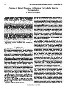
The encoder is a parallel concatenation of two 16-state duo-binary recursive systematic convolutional (RSC) encoders, fed by blocks of k bits (N= k/2 couples).
Both component encoders have identical features (Error! Reference source not found.): - 16-state duo-binary convolutional code - polynomials 23 (recursivity, period 15), 35 (redundancy) - first bit (A) on tap 1, second bit (B) on taps 1, D and D3 - circular termination for both component encoders
Changing the information block length k requires to change the permutation length N.
3
A
~~~~~~~~~~~~~(N)W
B
.................................................Ud~~~~~~~~~~~~~~~~~............
..............................
..........
N =k/2puncturingd
...............................
Y Redundancy part
couples of data
Figure 1: The TURBOD encoder (R 2 1/2) Figure 2 compares the performance of TurboD and that of the DVB-RCS turbo code, for a particular case (information block length in number of bits k = 1504, code rate R = 1/2, 2/3 and 3/4). The average improvement for medium coding rates (RA1/2) is about 1 dB for FER = 10-7, but this gain may be significantly higher for higher rates. l.Oe+00 l.Oe-O1 1.Oe-02 1.Oe-03 1.Oe-04
l.Oe-05 1.Oe-06
l.Oe-07 1.Oe-08 L
-1.5 -1 -0.5
1
0
0.5
1.5 2 Eb/NO (dB) 1
2.5
3
3.5
4
4.5
Figure 2: Performance comparison between TurbocD and DVB-RCS turbo code for QPSK. k = 1504, R = 1/2, 2/3 and 3/4. Max-Log-MAP component algorithm, 8 iterations, 4-bit quantization.
Figure 3-Figure 5 show the performance of the code with QPSK, 8PSK and 1 6APSK modulations for different code rates and information block lengths. The complexity of the decoder is of course increased with respect to the DVB-RCS code due to the use of a higher number of states, but it is still considered manageable considering the professional nature of the hub equipments where the turbo decoder is located.
4
QPSK modulation 6-bit quantization
---
---
k=1504 bits
8 iterations
0,1
0,01 1E-3 1E-4
1E-5 1E-6 1E-7 1E-8
1E-9 0,4
0,6
0,8
1,0
1,2
1,4
1,8
1,6
2,0
2,2
2,4
2,6
2,8
3,0
Figure 3: Performance of TurbocD with Max-Log-MAP decoding algorithm, 6-bit quantization, 8 iterations, AWGN. 188 bytes: R=0.39167, 0.43519, 0.48958, and 0.65278.
1,5
2,0
2,5
3,0
I
EB/NO3'5
4,0
4,5
5,0
Figure 4: Performance of TurboO with Max-Log-MAP decoding algorithm, 6-bit quantization, 8 iterations, AWGN with 8-PSK modulation. 163 bytes: R=0.56597, 216 bytes: R=0.5, 188 bytes: R=0.65278 and 376 bytes: R=0.52222 and R=0.65278.
5
4+12 APSK Modulation 6-bit quantization
0,1
8 iterations
---
: ...--...-T...
-
FER theoritical lirmits k=880 bits R=0.57292 v BER + FER k= 1728 bits R=0.56250 BER+ FER k=3008 bitsR=0.65278 BER S FER
Nl
0,01 E-
1 E-3
1 E-3 ::,: :::::: :,:
::...:::. ...... a: : ::: : :
,, k=3008 k- 1728
1E10 E
3,5
4,0
4,5
:: ::
..
. .. f
.{
5,0
::
---
5,5
6,0
----------
..1E-10
6,5
Eb/NO
Figure 5: Performance of Turbocb with Max-Log-MAP decoding algorithm, 6-bit quantization, 8 iterations, AWGN with 12+4-APSK modulation. 110 bytes: R=0.57292, 216 bytes: R=0.56250, and 376 bytes: R=0.65278, Zmax8.
Assuming a gain of about 1 dB with respect to the DVB-RCS turbo code for QPSK, the better performance can be exploited to either reduce the terminal transmit power by the same amount (for the same link BER) or to improve the system spectral efficiency. A reduction of transmit power in the terminal would imply cost savings mainly for a lower power SSPA and cheaper IDU power supply. The increase on system efficiency would instead result in the possibility to close the link with QPSK 2/3 instead of ¼/ with a gain in capacity of about 30%. 2. High Order Modulations with ACM ACM is a sophisticated form of data rate control in which information rate is adapted by changing modulation and coding rate whilst maintaining a constant symbol rate on the channel. A system analysis applied to the return link of multi-beam satellites is provided in Ref. 3. As far as modulation formats are concerned, preference to QPSK or BPSK has been always given in the SATCOM systems for the higher power etficiency of such modulation formats and typically limited user terminal EJRP's. However, this typically implies a waste of power/throughput particularly in Ka-band as for most of the time propagation conditions are good and better use of the SIT power could be made in such conditions. In particular, more bandwidth efficient modulation and coding modes could be used for most of the time without requiring increasing the power budget with reference to current systems. The adaptation of the transmission format may also be used to compensate for geographical variations such the satellite antenna receiving pattern, the interference distribution and terminal antenna miss-pointing. Such effects may cause several dB's of variations in the link budget. Current RCS systems mainly limit to the use of power control to adjust to the link conditions variability. With power control the transmit power is changed to compensate for the estimated attenuation on the up-link. Instead of changing the transmit power, the gateway control feedback (SNIR-based) signal may well be used for adapting the data rate (e.g. by using adaptive modulation and coding). Some care should be paid to the design of the ACM control loop as the TDMA nature of the return link implies interference power fluctuations thus asking for additional
margin .
The ACM technique strategy, i.e. play with the modulation/coding to adapt the data rate to the user propagation and interference conditions, naturally tends to optimize the overall system throughput. Some rate adaptation may be performed by the just changing the code rate only (AC, i.e. Adaptive Coding) while keeping the same modulation format (i.e. QPSK). However, the total SNIR range that such technique can cover is limited to about 3.5 4 dB within the current DVB-RCS standard, corresponding to the difference between the decoder thresholds of code rates 1/3 and 6/7. Such limited range would force to jointly use DRA (Dynamic Rate Adaptation, i.e. adaptation of the
6
carrier symbol rate) in order to cover the higher SNIR ranges imposed by typical Ka-band fading dynamics. However, it is well known that the DRA technique does not achieve the same overall throughput as ACM. Higher order modulations are thus required to support full ACM functionalities over Ka-band links, in particular 8PSK and possibly 16 APSK constellations. The TurbocD solution described in the previous section already supports high order modulations with a total SNIR range of about 16 dB (11 dB with just QPSK and 8PSK).
Typical throughput increase provided by the inclusion of ACM in Ka-band multi-beam systems is between 50% to 100% depending on system parameters.
3. Enhanced Layer 2 Encapsulation and Framing In today DVB-RCS systems Adaptive Coding (AC) may be implemented through fixed assignment of a physical layer format to each carrier and through ST frequency hopping in case of a rate change. However, the introduction of higher order modulations and ACM calls for the adoption of a more flexible framing format than what is currently used. The principle of "carrier segregation", i.e. separation of the available bandwidth in groups of carriers with a specific physical layer mode, becomes indeed inefficient when utilizing a large number of coding rates and modulation formats. The same carrier should then carry bursts transmitted with different physical layer modes.
The choice of a fixed burst length on the channel, regardless of the physical layer mode, appears preferable to the assumption of a fixed information length burst, like it is assumed in current DVB-RCS systems (e.g. MPEG). The main reasons are: i) absence of padding at the end of the frame: see Figure 6 where the comparison between the typical frame arrangements in slots of an RCS system implementing ACM is shown, with fixed information slot length and fixed channel slot length; ii) easier scheduling of low-jitter VoIP packets, which are normally evenly spread across the superframe; iii) possibility of applying interference cancellation algorithms, as discussed in the next sections, because of preambles alignment The burst length size should be selected taking into account coding efficiency, traffic profiles and encapsulation overhead. Frequency
Frequency s
1024 kS/s
|
Slot
Slot 12
13 512 kS/s 512 kS/s 256 kS/s
Slot 7 Slot 3
Slot
Slot
Slot 4
Slot
Slot 11 1 ms
Slot 9
Slot 10
Slot 1 1
|
Slot 5 Slt1So Slot 2
Slot 6
2_
bupertramei auuatiu
Slot 13 1Ms
4
basic slots
Slot 14 I ms
Slot 15 1 ms
Slot 16 1 ms
Slot 17 1 m
Slot 18 I ms
I/
Slot10- 2ms
512 kS/s
Slot7 -2ms
Slot8 -2ms
Slot9 -2ms
512EkSs
Slot 3 - 2 ms
Slot 4 - 2 ms
Slot 5 - 2 ms Slot 6 - 2 ms Slot 2 - 4 ms
Time25 n
Slot 12 I ms
using
1024 kS/s
18
14 Slot 8
T
Slot 17
Slot 16
Slot 15
Burst
kSs
._
Slot I 4 ms
Superframe duration is a multiple of 4 ms
Fill problem
Figure 6: Typical frame format with ACM and MPEG-based slots (on the left) and fixed channel burst size (on the right) The adoption of the above described flexible frame format needs to be coupled with a novel encapsulation scheme, capable of encapsulating IP and other upper layer packets into variable length information slots. The Generic Stream Encapsulation (GSE) Protocol5, which is being standardized for the GS profile of the DVB-S2 standard, appears applicable to the return link as well. Expected gains in terms of overhead with respect to MPE/MPEG encapsulation range from 40% to 100% depending on the IP packet length. Moreover, it offers the possibility of concatenating IP packets within the same burst, as well as fragmenting IP packets into multiple bursts. 4. Co-Channel Interference Cancellation Techniques Interference mitigation techniques can be introduced to increase the system throughput in interference-limited
7
Time
systems. In particular, in multi-beam systems one can take advantage of the space diversity generated by the satellite antenna pattern to mitigate inter-beam interference and significantly improve system throughput. This is achieved through jointly processing at the gateway (GW) of the signals received from co-frequency beams. The resulting system is described by a Multiple Input Multiple Output (MIMO) architecture, in which the inputs are provided by the user of interest and the co-channel interferers, while the multiple outputs are the signals received by the different antenna beams and transparently transmitted to the GW (see Figure 7).
Figure 7: Conceptual System block diagram with interference cancellation support Two techniques have been shown6 to be capable of achieving important throughput gain with an affordable complexity, i.e. the Spatial MMSE (S-MMSE) and the SMMSE-Serial Interference Cancellation (S-MMSE-SIC). The S-MMSE receiver has several attributes that makes it appealing. The MMSE receiver is known to generate a soft decision output which maximizes the output Signal to interference plus Noise ratio (whereas in an AWGN channel with no interference, the match filter maximizes the output SNR). A linear S-MMSE filter has also the advantage of a rather low complexity implementation. The detailed derivation of the S-MMSE matrix is included in Ref. 6. In the same reference a channel estimation technique based on the processing of the preambles of the received interfering bursts is described. Simulation results show how the proposed algorithm is quite robust to phase and amplitude errors, with capacity losses due to incorrect channel estimation of 5-10%. In combination with the S-MMSE filtering, an interference cancellation algorithm can be implemented (S-MMSESIC). The idea is based on successive interference cancellation where, after MMSE spatial filtering, each user is decoded, re-encoded and subtracted off the transmitted signal. To cancel the re-encoded signal, the estimated channel matrix is used. After each cancellation, a new MMSE filter is recomputed for a reduced size MMSE matrix. The decoding process is normally implemented following an order, which is based on the user signal strength (C/(N+I) value). A detailed description of the algorithm can be found in Ref. 6.
Both techniques can be used in combination with ACM, assuming that user terminals can transmit with different physical layer modes depending on the signal quality achieved after cancellation. The throughput gain achievable is of course dependent on the number of simultaneously processed channels.
8
For typical multi-beam Ka-band systems capacity gains of 50-70 % are expected as the results of application of cuch techniques. 5. Adjacent Channel Interference Cancellation Techniques A technique, which may improve spectral efficiency on the RL without recurring to spatial processing (not applicable for single beam systems), is the use of a more dense channelization in which the allocated frequency slot is undersized with respect to the actual carrier bandwidth. A larger number of carriers can thus be packed in a given bandwidth and, if the increase in Adjacent Channel Interference (ACI) can be suitably mitigated, a net gain in spectral efficiency can be achieved. The following techniques seem to be the most promising for mitigating interference from adjacent carriers: i) Single User Matched Filter and iterative interference cancellation (SUMF-IC) and ii) Unconditional linear MMSE and iterative interference cancellation (U-MMSE-IC).
Both algorithms can be illustrated by the principle architecture of Figure 8.
,~~~~~~~~~~~~~~~~s=. . ......... MUD
front-end
Figure 8: Turbo-MUD principle
The main blocks in the above architecture are: * An interference cancellation multiuser detector (IC-MUD) able to provide soft information to the following bank of SISO decoders. It is fed with the observed signal Y and the extrinsic information produced by the decoders * A bank of K SISO decoders able to provide extrinsic information for the feedback and APP for the final detection. For the SUMF-IC, the MUD front-end is made by a simple bank of matched filters. On the contrary, for the ULMMSE-IC, the MUD front end delivers as output a refined estimation of the input signal through LMMSE filtering of the original input signal partially cleaned from interference. This corresponds to assuming a Gaussian distribution of the extrinsic information and requires estimating the mean vector and covariance matrix of the extrinsic information in order to compute the optimal LMMSE filter. Through LMMSE filtering, the algorithm minimizes the mean square error between each of its outputs and the transmitted symbols conditioned on the values of the extrinsic information provided by the SISO decoders. In the Unconditional implementation, the LMMSE filter is computed only once per iteration and per user, in order to decrease implementation complexity. More details on these algorithms can be found in Ref. 7.
6. Contention-based Access Scheme: the CRDSA technique Current satellite standards for interactive satellite broadband networks like DVB-RCS and the Telecommunication Industry Association (TIA) IP over Satellite (IPoS) provide the capability to transmit data on the return link through
9
a Demand Assignment Multiple Access channel (DAMA). Initial capacity requests and short packet transmissions are sent through a Random Access (RA) channel using the Slotted Aloha (SA) protocol in DVB-RCS or the Diversity Slotted Aloha (DSA) protocol in IPoS. DAMA-based access schemes are suitable for long packet transmissions or for terminals offering a medium to high level of traffic aggregation. However, their response time is too high for low duty-cycle bursty traffic sources.
In consumer type of interactive Satellite Terminals (ST), the amount of traffic aggregation at the ST will largely decrease and consequently the Random Access (RA) channel utilization potential will increase. In fact, although SA represents today a well established Random Access technique for TDMA satellite networks doubling the maximum throughput compared to the pure Aloha protocol, its utilization is typically limited to initial login and/or capacity request or MAC signalling packets. This is because in practice SA works with very moderate normalized average loading (e.g. 2-5 %) to ensure acceptable packets transmission delay and loss probability.
DSA provides better delay and throughput performance than SA for very moderate loading conditions by transmitting twice the same packet in a different TDMA slot, or a different frequency and time slot in case of MultiFrequency TDMA (MF-TDMA). However, the throughput difference between Aloha and Slotted Aloha or Diversity Slotted Aloha is limited and quite poor in absolute terms due to the moderate loading conditions. It is therefore pivotal to enhance the RA channel performance in terms of throughput and delay with minimum impact on the existing satellite standards.
The novel Contention Resolution Diversity Slotted Aloha (CRDSA) scheme described in Reference 8 represents an improved version of the well known SA and DSA schemes. Similarly to DSA, the CRDSA protocol key idea is to transmit two replicas of the same burst at random time within a frame instead of only once as in SA. While the driver for DSA is to slightly enhance the SA performance by increasing the probability of packet successful transmission at the expense of increased RA load, CRDSA in addition is able to resolve most of the DSA packet contentions. Burst collisions are cleared up at the gateway through a simple yet effective iterative Interference Cancellation (IC) approach that uses information from the replica bursts. Each burst transmitted contains embedded in the coded payload bits information about the "twin" or replica burst slot location within the TDMA frame. The CRDSA scheme assumes that the TDMA frame baseband complex samples are stored in memory at the gateway. Processing takes place on a slot-by-slot basis by scanning the full frame and then repeating the frame scan a number of times (typically 8-10). If a burst is received at the gateway without collisions ("clean burst") then the gateway can remove through simple IC its "twin" burst from the frame using channel estimation (amplitude, timing) coming from the demodulated "clean" burst. The carrier phase estimation process for IC is instead more complex and can be found in Ref. 8. Through this iterative demodulation and IC process it possible to largely increase the number of received burst in the presence of high channel load.
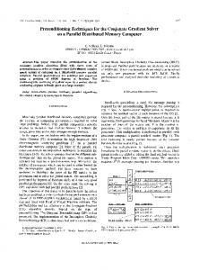
The main CRDSA advantages lie in the improved packet loss ratio and reduced packet delivery delay performance versus channel load jointly with a much higher operational throughput compared to SA and DSA. In Figure 9 the throughput of the CRDSA protocol has been first simulated versus the normalized load' for the case of Poisson traffic for a variable number of maximum iterations (ANtax =1, 2, 5, 10, 15) in the contention resolution process and under the assumption of perfect channel estimation for IC. The case of N x 1 corresponds to the case of DSA. To remark that while standard SA reaches its throughput peak of 0.36 for a normalized load of 1, CRDSA achieves a peak throughput of about 0.52 for a normalized load of 0.65. These simulation results have been favourably compared to an analytical upper bound derived in Ref.8
The definition of normalized MAC load G measured in packets per slot accounts for the dual burst transmission in case of CRDSA, e.g. a normalized MAC load of 0.4 packets per slot would correspond to a physical channel load of 1
0.8.
10
2nd iter 5th ter
Ot iter 0.55 -_----10th ---- 15 ter.1 5th iter
DSA --SA
--
0.5
0.45 _
---------------
-------------------
0.4 _ 0) 0
0.35 _
...........
..............
0.3 A
A
.A ..
0.25 _
0.2 I.......
0.15 _ n} i .-/ U. t-
0.1
0.2
0.3
A.4
0.6 0.5 Normalized load [G]
0.7
0.8
0.9
Figure 9: Throughput for CRDSA (dotted line) for number of iterations Nteax =2, 5, 10, 15, SA (dashed), DSA (dashed dot) with ideal CRDSA channel estimation for IC. Let us now define the MAC packet loss ratio
as
PLR
c(G) = I T(G) being G the normalized load and T the MAC G
throughput. Figure 10 reports the MAC packet loss ratio PLRvC(G) for the SA, DSA and CRDSA cases. In practice, to allow for stable operations, RA protocols are operating when the burst MAC loss ratio is relatively small, e.g. 2 %. This corresponds to an average throughput of 0.35 for CRDSA and 0.02 for SA and 0.075 for DSA. Thus, under practical working conditions, the throughput increase for CRDSA is very remarkable and corresponds respectively to about 17.5 times the SA and 4.4 times the DSA ones.
11
CRDSA SA --DSA 60
II
--
50
40
P/k
lo
0
07 0. 0 (U.2 03 0~~~~~~~~~~~Nralzdla G
perfrmace f te aces sytem satelitenetorksLoki
lrgevaretyofNormalized load
.7
0
[G]rfi
yialo
rabn (das hePDFdot) wthe siduaeal CRDASAchnescestmeation foranmssoIC.rIa vera
roie
important percentage of packets is transmitted in RA mode. This corresponds mainly to the web client packets. For small bursts, the CRDSA-DA end-to-end delay is about three times less compared to the DA-only scenario (i.e. from 1.1I s down to 0.3 5 s) and shall yield a much better perception to the user of the satellite channel interactivity.
12
0.03
O.025
Web client packets
...
_
Web server packets ----
0 .02
0.015---
0.005
.,e
I
..
000
0
0.5
1.5
1
Delay (s) Figure 11: Separate delay PDF in CRDSA-DA for Web client and Web
2 server
2.5
packets for G=0.75.
References
ETSI EN 301 790 V1.2.2 (2000-12), Digital Video Broadcasting (DVB); "Interaction channel for satellite distribution systems". Available on the DVB organisation web site (http://www.dvb.org) or ETSI web site (http://www.etsi.org). 2 ETSI EN 301 307 Digital Video Broadcasting (DVB); "Second generation framing structure, channel coding and modulation systems for Broadcasting, Interactive Services, News Gathering and other Broadband satellite applications".
1
Available on ETSI web site (http://www.etsi.org). 3 R. Rinaldo and R. De Gaudenzi, "Capacity Analysis and System Optimization for the Reverse Link of Multibeam Satellite Broadband Systems Exploiting Adaptive Coding and Modulation", Intemational Joumal of Satellite Commun. and Network., 2004, vol. 22, page 425-448.
4 S. Cioni, R. De Gaudenzi, R. Rinaldo "Adaptive Coding and Modulation for the Reverse Link of Broadband Satellite Networks " in the proceeding of Globecom 2004, Dallas 5 Ulrik De Bie, Bernhard Collini-Nocker, Gorry Fairhurst, Alberto Ginesi, Axel Jahn, Rita Rinaldo, Oscar Del Rio "GSE: DVB-S2 Generic Stream IP Encapsulation Protocol", Available on the DVB organisation web site (http://www.dvb.org) 6 M. Debbah, G. Gallinaro, R. Muller, R. Rinaldo, A. Vernucci "Interference Mitigation for the Reverse-Link of Interactive Satellite Networks", SPSC 06 workhop, ESA/ESTEC Sept. 11-13 2006 7 J. Boutros, G.Caire "Iterative Multiuser Joint Decoding: Unified Framework and Asymptotic Analysis", IEEE Transactions on Information Theory, Vol. 48, No. 7, July 2002 8 0. Del Rio Herrero, E. Casini, R. De Gaudenzi, Contention Resolution Diversity Slotted Aloha Plus Demand Assignment (CRDSA-DA), 23rd AIAA ICSC-2005, September 2005, Rome
13