Tim Dwyer and George Robertson. Microsoft Research,. Redmond, USA. {timdwyer,ggr}@microsoft.com. Abstract. Recent work on constrained graph layout has ...
Layout with Circular and Other Non-linear Constraints Using Procrustes Projection Tim Dwyer and George Robertson Microsoft Research, Redmond, USA {timdwyer,ggr}@microsoft.com
Abstract. Recent work on constrained graph layout has involved projection of simple two-variable linear equality and inequality constraints in the context of majorization or gradient-projection based optimization. While useful classes of containment, alignment and rectangular non-overlap constraints could be built using this framework, a severe limitation was that the layout used an axis-separation approach such that all constraints had to be axis aligned. In this paper we use techniques from Procrustes Analysis to extend the gradient-projection approach to useful types of non-linear constraints. The constraints require subgraphs to be locally fixed into various geometries—such as circular cycles or local layout obtained by a combinatorial algorithm (e.g. orthogonal or layered-directed)—but then allow these sub-graph geometries to be integrated into a larger layout through translation, rotation and scaling.
1
Introduction
Our past work has explored methods for incorporating various types of constraints over node positions and edge routing into force-directed layout. A key component in achieving stable incremental constraint satisfaction in the context of such layout has been gradient-projection techniques. Optimization of a goal function subject to constraints using gradient projection involves finding a gradient related descent vector which is then projected against the constraints to obtain a descent vector that is feasible with respect to those constraints. Projection, as described in Section 3, involves solving a constrained least-squares problem. Recent work has focused on interactive applications of such constraint-based layout. For example, a diagram authoring tool [11] and on-line exploration of large graphs [8]. To achieve interactive responsiveness in such applications the projection step needs to be efficient and for certain classes of constraints we have been able to find methods of projection that compare favourably in running time to the basic unconstrained layout. In [6] we gave a simple active-set algorithm for projection subject to orthogonal ordering constraints; i.e. a partial ordering of nodes in either the horizontal or vertical axes of the drawing. In [7] we gave an algorithm for more general separation constraints: linear equality or inequality constraints over pairs of either x- or y-position variables. D. Eppstein and E.R. Gansner (Eds.): GD 2009, LNCS 5849, pp. 393–404, 2010. c Springer-Verlag Berlin Heidelberg 2010 �
394
T. Dwyer and G. Robertson
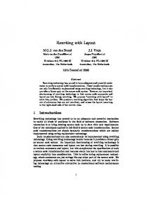
Fig. 1. A metabolic pathway network with two cycles arranged in two ways using different (user defined) constraints. In both cases Procrustes projection (see Section 4) is used to keep the cycles circular and groups are created around the two cyclic components. Constraints prevent members of these groups from overlapping with other parts of the graph. In the lower-left drawing the non-overlap constraint is based on the convex-hulls of the groups, projected apart as described in Section 3.2. The upper-right drawing is arranged with rectangular group boundaries using separation constraints (see Section 3.1). Various horizontal and vertical alignment constraints (using equality separation constraints) have been added interactively by the user to customize the layouts.
Most recently, following position-based dynamics approaches used successfully in computer game animation, we showed that a simple class of nonlinear constraint could also be projected in a cyclical Gauss-Seidel scheme [5]. The constraints were simple equalities or inequalities over Euclidean distance between pairs of nodes. Although simple, we were able to compose these constraints into more complex rigid structures. In particular we demonstrated wheel-like constructions to draw directed-graph cycles in a reorientable, but fixed radius circle. Such circular constraints are useful for achieving the kind of drawing conventions commonly seen, for example, in biology textbooks, for drawing cycles in metabolic pathways. Although projecting cycles in this way was successful it led us to an investigation to see whether a closed-form solution to the projection of such circular constraints was possible. Also, we wanted circular constraints with variable as well
Layout with Circular and Other Non-linear Constraints
395
as fixed radii. In this paper we show that the technique of Procrustes analysis— more commonly used by statisticians to fit experimental observations to a model— efficiently solves this exact problem and further more, can be used to obtain a projection of any rigid shape with minimal translation, rotation and scaling.
2
Related Work
A survey of graph-drawing literature—particularly regarding circular layout style—reveals a number of scenarios where the Procrustes projection described in this paper could provide a concrete improvement to either the quality of the drawings or the stability of the layout method. Six and Tollis [19] give a multi-stage force-directed approach for layout of circular subgraphs in a non-circular arrangement of the larger graph. At first the subgraphs are replaced with single nodes and this abridged graph is arranged using a typical force-directed technique. Then a circular ordering of the subgraphs is found to minimize internal edge-crossings. The radius of each circle is fixed based on the number of nodes and an orientation is found by what sounds like a brute-force search. Finally, another relaxation step is applied using an ad-hoc local search method over node angles. Becker and Rojas [2] discuss a technique for drawing the cycles in metabolic pathways as circles. They do not give many algorithmic details but the brief description of their two-stage force-directed approach suggests that it is similar in spirit to Six and Tollis. Baur and Brandes [1] investigate techniques for circular ordering of nodes in subgraphs to minimize crossings between both edges internal to the subgraph, and edges linking the subgraph to other circular subgraphs in so called “Micro/Macro” graphs, i.e. graphs with one level of semantic grouping. They do not consider the problem of orienting the circular “micro” graphs in the context of the larger “macro” graph layout and in many of their examples it is clear that a little rotation of the circles would significantly reduce edge length. Friedrich and Eades [14] give a complicated (and unproven) algebraic expression for finding an affine transformation of a graph to transition between different layouts such that squared displacement of the transformed graph from the target graph is minimized. This is exactly a Procrustes problem although Friedrich and Eades also allow shear transformations. Shearing is forbidden by the orthogonal Procrustes model described in Section 4 since shearing does not preserve the “shape” of the model and can collapse the dimensionality: e.g. transform a 2-d shape to a line [4, pg. 430]. In addition the Procrustes formulation that follows is easier to describe, implement and debug and does not suffer from potential singularities that may be a problem in the formulation in [14] (Friedrich and Eades do not explain how to handle zero value denominators in their expression).
3
Constraint Projection
A key ingredient to the constraint-based layout described in this paper is the idea of solving a projection problem. Projecting the variables x = (x1 , . . . , xn )
396
T. Dwyer and G. Robertson
with starting or desired positions d = (d1 , . . . , dn ) against a set of constraints that define a feasible region S means finding the point x in S closest to d. arg min x∈S
n �
(xi − di )2
(1)
i=1
While we have in the past considered different ways to project against certain classes of constraints using specially developed solver techniques, this is the first paper where we have combined different projection methods for different classes of constraints in a single unifying framework. Before introducing the new type of Procrustes constraint projection in Section 4, we briefly review the two other types of constraint projection that will be used in combination. 3.1
Separation Constraint Projection
A separation constraint is an equality or inequality between a pair of (exclusively) horizontal or vertical node positions. For example, ux + g ≤ vx requires that nodes u and v be separated horizontally by at least g. In [7] and also [11] we give gradient projection techniques for layout using only such horizontal and vertical separation constraints. They are useful for many drawing conventions involving constraints that are aligned with the page or screen axes such as rectangular node and cluster non-overlap constraints, constraints requiring the end node of a directed edge be strictly above the start node, or for persistent horizontal or vertical alignments. Efficient scan-line techniques for generating horizontal or vertical non-overlap constraints have been developed, see [9]. We also have fast techniques for finding the projection of all separation constraints in a given axis, see [7]. Although separation constraints are useful there are many drawing conventions requiring non-linear constraints, or linear constraints that are not axis aligned. In [10] and [12] we experimented with augmentation of the goal function to simulate other types of constraint. Simply adding terms to the goal function, however, does not provide the strict “rigidity” of real constraints. Increasing the weighting of such terms to reduce “stretchiness” usually overwhelms the underlying layout goal function or can lead to instability. 3.2
Euclidean Distance Projection
A Euclidean distance constraint of the form |pq| ≥ d requires a minimum distance d between the positions of two nodes p and q. If such a constraint is violated the projection, i.e. feasible positions p� and q� that minimize the wq r, squared displacement from p and q, are trivially computed as p� = p − wp +w q w p � −1 q = q + wp +wq r where r = |pq| (d − |pq|)pq. The “weights” wp and wq for p and q are by default 1. However, for a constraint involving a cluster of n nodes it is useful to take the weight as n. In [5] Euclidean distance constraints (including equality constraints) were the only type of constraint and the above calculation was the only type of projection used. Complex constraints like rigid circles were built with a wheel-like frame of
Layout with Circular and Other Non-linear Constraints
397
Euclidean distance equality constraints. The Procrustes projection technique described in Section 4 makes this usage redundant. However, this type of Euclidean distance projection is still useful in the framework described in Section 5, for preventing overlap between the convex hulls of node/cluster boundaries. That is, given two overlapping convex hulls we can minimally project them apart by chosing the displacement vector r (above) from the minimum penetration depth vector, computed from the Minkowski Difference of the two hulls, see Figure 2. The time to compute this vector is proportional to the sum of vertices in the two hulls. We use a binary space partition tree to quickly identify potentially overlapping hulls (rather than computing Minkowski Differences for all pairs). Figure 1 shows a graph with non-overlapping cluster boundaries projected apart using this technique.
Fig. 2. To prevent overlap between convex hull cluster boundaries and nodes or other cluster boundaries we project apart overlapping boundaries using the minimum penetration depth vector
4
Procrustes Projection
Procrustes analysis is a technique for fitting an observed data configuration to an expected model using only linear transformations. Borg and Groenen [4] give a comprehensive overview and introduction to Procrustes methods, although the techniques have been known to statisticians since the 1950s. For a statistical technique, it is rather colourfully named after the character in Greek mythology of the same name. Procrustes was a keeper of an inn who “fit” his victims to an iron bed using drastic means. The problem that we consider in this paper is projecting a set of n 2-d points X onto a target constrained configuration Y with a shape that is rigid but which can be scaled by a factor s, translated by a vector t or rotated by an orthogonal matrix T such that the sum of squared distances from the transformed Y to the original X is minimized. That is, we want to find s, t and T that minimize: n � 2 (Xi − (sYi T + t)) (2) i=1
subject to T � T = I, i.e. only orthogonal rotation. The optimal translation vector t is optained by differentiating (2) with respect to t and setting the derivative equal to 0 (see [4]): n
1� (Xi − sYi T ) t= n i=1
(3)
398
T. Dwyer and G. Robertson
The optimal scale s is obtained similarly by substituting (3) for t in (2), differentiating with respect to s and setting this derivative to 0 giving: s=
tr X � Y T tr Y � Y
(4)
where tr is the matrix trace of the 2 × 2 result of the inner products. Note that this assumes that Y is centered on the origin (or has been centered by subtracting the barycenter of Y from all of its elements). Substituting (3) and (4) into (2) we see that the optimal rotation T is invariant to scale or translation. Conveniently, it can be shown (see Appendix) that T = QP � , where P and Q are found from the singular value decomposition X � Y = P ΦQ� , is exactly the optimal rotation. The singular value decomposition of the 2 × 2 matrix X � Y can be obtained in closed form using the quadratic formula to find roots of the characteristic polynomial. To summarize, the following procedure takes a matrix X of n points (i.e. node positions), a matrix Y of n points with the target configuration (centered on the origin), and returns the projection of X on the optimally transformed Y : procedure ProjectXonY(X, Y ) C ← X�Y (P, Φ, Q� ) ← SingularValueDecomposition(C) T ← QP � s ← (tr� CT )/(tr Y � Y ) t ← n1 n i=1 (Xi − sYi T ) return sT � Y � + 1� t
�ŝƐƉůĂĐĞŵĞŶƚ
Procedure ProjectXonY runs in O(n) time since the most expensive operation is computing the inner-product of n × 2 matrices.
ϮϬϬ ϭϴϬ ϭϲϬ ϭϰϬ ϭϮϬ ϭϬϬ ϴϬ ϲϬ ϰϬ ϮϬ Ϭ ϭ
ϱ
ϵ
ϭϯ
ϭϳ
/ƚĞƌĂƚŝŽŶ
(a) Unconstrained
(b) With circle constraints
(c) Convergence
Fig. 3. Circular constraints applied using cyclical Gauss-Seidel Procrustes projection can even be interlocking. Provided a feasible solution exists, and the starting layout is reasonably untangled (e.g. the unconstrained layout on the left) cyclical projection rapidly converges (see Section 5.1).
Layout with Circular and Other Non-linear Constraints
4.1
399
Choosing the Target Configuration
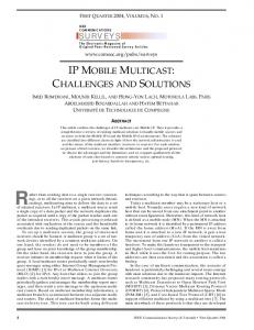
The target configuration matrix Y can be any shape centered at the origin. For example, to require that n nodes be equally spaced in a given order around a circle we simply chose Y as the vector of n points (y1 , . . . , yn ) where yi = (cos iθ, sin iθ) taking θ = 2π n . Figures 1, 3 and 6 show the results of using such circular constraints—in combination with other constraints—in the constrained layout scheme described in Section 5. The target configuration can equally easily be the result of a complete layout algorithm applied to the subgraph. Figure 6(c) demonstrates this by taking the target configuration Y as the result of a layered layout algorithm applied to subgraphs with tree structure.
5
Combining Constraints in an Incremental Layout Step
The procedure FeasibleLayoutStep summarizes the operations in a single iteration of layout for a graph G = (V, E), with nodes initially positioned horizontally and vertically at Vx and Vy respectively, a set C of Procrustes or any other constraints that we know how to project and horizontal and vertical separation constraints Ch and Cv respectively. The last parameter α controls the size of the unconstrained descent step, see below. procedure FeasibleLayoutStep(V, E, C, Ch , Cv , α) D ← ComputeDescentDirection(V, E, α) d ← D − (Vx , Vy ) ¯ ← ProjectDesiredPositions(C, D) D Ch� ← Ch ∪ GenerateHorizontalNonOverlapConstraints(Vx , Vy ) ¯ x) x ← P roject(Ch� , D � Cv ← Cv ∪ GenerateVerticalNonOverlapConstraints(x, Vy ) ¯y) y ← P roject(Cv� , D return (x, y), |d|
This procedure returns new positions (x, y) which improve the layout (depending on the quality of the result of ComputeDescentDirection), which are strictly feasible with respect to the separation constraints Ch , Cv and generated non-overlap constraints, and which are close to feasible with respect to the other constraints C. We discuss exactly what we mean by close to feasible in Section 5.1. We also return the size of the unconstrained gradient-descent step d. This is useful in heuristics for determining appropriate step-size α. We have had success using the adaptive trust-region step-size selection method proposed by Hu [15]. Though more costly, optimum step-size selection or Armijo Rules [3] could also be used to guarantee strict improvement as in [8]. The procedure ComputeDescentDirection returns updated positions for the nodes V after taking a gradient-related step, with size controlled by α to reduce a layout cost function. This could equally well be an unconstrained iteration of the p-stress minimization method described in [8] or an iteration of any “force”based approach. In our experiments we use a Fast-Multipole method following Lauther [17] so that ComputeDescentDirection completes in O(|V | log |V | + |E|) time.
400
T. Dwyer and G. Robertson
Fig. 4. A mesh graph with 576 nodes and eight circle constraints, used in timing and convergence tests ϴϬϬϬ
ϳϬϬϬ
ϲϬϬϬ
�ŝƐƉůĂĐĞŵĞŶƚ
ϱϬϬϬ
ϰϬϬϬ
ϯϬϬϬ
ϮϬϬϬ
ϭϬϬϬ
Ϭ tŚĞĞů
Ϭ
ϭ
Ϯ
ϯ
ϰ
ϱ
ϲ
ϳ
ϴ
ϵ
ϭϬ
ϭϭ
ϭϮ
ϭϯ
ϭϰ
ϭϱ
ϭϲ
ϭϳ
ϭϴ
ϭϵ
ϲϴϱϬϭϳϲϬϭϬϴϵ ϳϬϬ ϰϳϰ ϯϮϱ Ϯϯϭ ϭϳϮ ϭϯϯ ϭϬϴ ϵϮ͘ϰ ϴϮ͘ϭ ϳϰ͘ϵ ϲϵ͘ϳ ϲϱ͘ϴ ϲϯ ϲϬ͘ϵ ϱϵ͘ϭ ϱϳ͘ϲ ϱϲ͘ϱ
WƌŽĐƌƵƐƚĞƐ ϰϮϲϯ Ϭ͘ϯϯ Ϭ͘ϬϬ
Fig. 5. Total node displacement (the units are roughly screen pixels) versus iteration of constraint projection for the graph in Figure 4 using either Procrustes circle constraints or a wheel of Euclidean distance constraints
Layout with Circular and Other Non-linear Constraints
(a) Unconstrained
(b) Mixing a circular constraint with axisaligned separation constraints to prevent overlap between nodes and to require directed edges to point downwards.
(c) In addition to the Procrustes circle constraint for the nodes involved in the cycle, this example shows the three subtrees constrained to layered configurations obtained with a Sugiyama algorithm, i.e. the local layout is used as the target configuration for Procrustes projection, which determines the optimal scale and rotation. Note, the subtrees could just as easily be DAGs or undirected subgraphs arranged with another algorithm, e.g. orthogonal layout. Fig. 6. The citrate cycle metabolic pathway, arranged using various constraints
401
402
5.1
T. Dwyer and G. Robertson
Gauss-Seidel Gradient Projection
For solving systems of linear equations, an iterative method of updating one variable at a time to satisfy one or more of the equations is commonly attributed to Gauss-Seidel. Jakobsen [16] and more recently M¨ uller et al. [18] describe techniques using iterative constraint projection for rigid skeletal animation and cloth simulation in computer games, as “Gauss-Seidel” approaches. Although we know of no formal proof for the convergence of such methods our experiments with simple two-node constraints (see [5]) indicate that they work well in practical layout applications. In this paper we explore, for the first time, application of this approach to combining projection of different classes of constraints using different solver techniques. That is, whereas in [5] we considered only Euclidean distance constraints between pairs of nodes, in this paper we combine these with Procrustes projection and separation constraint projection giving us faster convergence, more stable interactive layout, and more flexible constraints. Thus, the procedure ProjectDesiredPositions returns new positions for nodes by—starting from the desired positions D—cyclically projecting each constraint in C (note that C also conceptually includes any convex-hull non-overlap requirement, although the precise Euclidean projection operations are determined dynamically as per Section 3.2). Figure 5 shows a comparison of total displacement of nodes for the large example in Figure 4 with circular constraints using either wheel-like meshes of Euclidean distance constraints (see [5]) projected as described in Section 3.2 or Procrustes projection using the procedure ProjectXonY as in Section 4. Clearly, far fewer iterations are required for Procrustes projection. 5.2
Separation Constraint Projection
The final steps of ComputeDescentDirection apply axis-aligned separation constraints. The GenerateHorizontalNonOverlapConstraints uses the scan-line algorithm described in [9] to generate separation constraints to resolve horizontal overlap between rectangular node and cluster boundaries horizontally. Note that it uses the starting configuration Vx , Vy rather than the output of ProjectDesiredPositions. This is because, if the input is already feasible (i.e. not overlapping) the relative left-to-right arrangement of nodes should be preserved (unless nodes have, in the interim, moved vertically so that they can no longer potentially overlap horizontally). In practice we have found that this makes continuous layout while the user directly manipulates (drags) nodes much smoother and less surprising. The next call to Project invokes the separation constraint solver [9] to place ¯ subject to the nodes horizontally as close as possible to the desired positions D generated and user-defined separation constraints. Next, vertical non-overlap constraints are generated based on the newly computed feasible horizontal positions x and the previous vertical positions Vy (again to preserve any applicable previous vertical ordering). Finally, Project is called again to determine feasible vertical positions y.
Layout with Circular and Other Non-linear Constraints
403
Applying separation constraints last means that they are always satisfied, while the Procrustes and Euclidean distance constraints projected cyclically by ProjectDesiredPositions may be slightly violated. This works well as any violation of the axis aligned and rectangular non-overlap constraints tends to be more noticeable than for the other types of constraints. Still, since the whole FeasibleLayoutStep procedure is applied many times inside a larger layout loop, all constraints tend to be resolved after a few iterations.
6
Discussion, Conclusion, Further Work
Figures 1 and 6 give practical examples of how the various types of constraints we have described can be applied in practice. The Procrustes constraints are very fast compared to the overall layout process: Figure 4 with 576 nodes, 1104 edges and 8 circle constraints took (on a 2.1Ghz PC) 1.86 seconds total layout time with about 0.01 seconds spent in projection operations due to the convergence criteria described in Section 5.1. Further work should be done to time much larger, pathological examples to really explore the convergence properties of cyclical constraint projection. Static layout of all the other smaller examples in this paper takes a fraction of a second. The real benefit of fast constraint layout, however, is in supporting incremental layout scenarios. All of the examples in this paper were produced in an interactive system where users can directly manipulate nodes and edit the constraints, getting immediate feedback from “rigid” constraint structures. In addition to efficiency the Procrustes projection presented in this paper allows for variable radii circles enabling interlocking constraints as in Figure 3. Furthermore, they can be applied to obtain scaling and rigid rotation of any initial arrangement of nodes such as layout from a different algorithm, see Figure 6(c). The other contribution of this paper is to show that these and other types of constraints can be combined through cyclical projection as described in Section 5.1. Detecting satisfiability of constraints, and where satisfiable, finding a feasible starting configuration require much more research. One imperfect strategy is to detect if error does not significantly decrease inside the cyclical constraint satisfaction loop. Once unsatisfiable constraints have been detected, communicating this to the user in a way allows them to resolve the unsatisfiability is also a challenge. In our rudimentary interactive test systems, where constraints are added incrementally by the user, we have found the most useful strategy has been a simple undo facility to remove the most recently added constraint. Of course users unfamiliar with constraint layout would need an intuitive interface that prevents unsatisfiable constraints from being created at all. Acknowledgements. Thanks to Lev Nachmanson and Ted Hart for providing various pieces used in our layout software.
References 1. Baur, M., Brandes, U.: Multi-circular layout of micro/macro graphs. In: Hong, S.-H., Nishizeki, T., Quan, W. (eds.) GD 2007. LNCS, vol. 4875, pp. 255–267. Springer, Heidelberg (2008)
404
T. Dwyer and G. Robertson
2. Becker, M.Y., Rojas, I.: A graph layout algorithm for drawing metabolic pathways. Bioinformatics 17(5), 461–467 (2001) 3. Bertsekas, D.P.: Nonlinear Programming. Athena Scientific, Belmont (1999) 4. Borg, I., Groenen, P.J.F.: Modern Multidimensional Scaling: Theory and Applications, 2nd edn. Springer, Heidelberg (2005) 5. Dwyer, T.: Scalable, versatile and simple constrained graph layout. In: Proc. Eurographics/IEEE-VGTC Symp. on Visualization (Eurovis 2009). IEEE, Los Alamitos (2009) (to appear) 6. Dwyer, T., Koren, Y., Marriott, K.: Drawing directed graphs using quadratic programming. IEEE Transactions on Visualization and Computer Graphics 12(4), 536–548 (2006) 7. Dwyer, T., Koren, Y., Marriott, K.: IPSep-CoLa: an incremental procedure for separation constraint layout of graphs. IEEE Transactions on Visualization and Computer Graphics 12(5), 821–828 (2006) 8. Dwyer, T., Marriott, K., Schreiber, F., Stuckey, P.J., Woodward, M., Wybrow, M.: Exploration of networks using overview+detail with constraint-based cooperative layout. IEEE Transactions on Visualization and Computer Graphics 14(6), 1293– 1300 (2008) 9. Dwyer, T., Marriott, K., Stuckey, P.: Fast node overlap removal. In: Healy, P., Nikolov, N.S. (eds.) GD 2005. LNCS, vol. 3843, pp. 153–164. Springer, Heidelberg (2006) 10. Dwyer, T., Marriott, K., Wybrow, M.: Integrating edge routing into force-directed layout. In: Kaufmann, M., Wagner, D. (eds.) GD 2006. LNCS, vol. 4372, pp. 8–19. Springer, Heidelberg (2007) 11. Dwyer, T., Marriott, K., Wybrow, M.: Dunnart: A constraint-based network diagram authoring tool. In: Tollis, I.G., Patrignani, M. (eds.) GD 2008. LNCS, vol. 5417, pp. 420–431. Springer, Heidelberg (2009) 12. Dwyer, T., Marriott, K., Wybrow, M.: Topology preserving constrained graph layout. In: Tollis, I.G., Patrignani, M. (eds.) GD 2008. LNCS, vol. 5417, pp. 230–241. Springer, Heidelberg (2009) 13. Everson, R.: Orthogonal, but not orthonormal, procrustes problems. Advances in Computational Mathematics (submitted) (1998), http://secamlocal.ex.ac.uk/people/staff/reverson/uploads/Site/ procrustes.pdf 14. Friedrich, C., Eades, P.: Graph drawing in motion. Graph Algorithms and Applications 6(3), 353–370 (2002) 15. Hu, Y.: Efficient and high quality force-directed graph drawing. The Mathematica Journal 10(1), 37–71 (2005) 16. Jakobsen, T.: Advanced character physics. In: San Jose Games Developers’ Conference (2001), http://www.gamasutra.com/resource_guide/20030121/jacobson_01.shtml 17. Lauther, U.: Multipole-based force approximation revisited - a simple but fast implementation using a dynamized enclosing-circle-enhanced k-d-tree. In: Kaufmann, M., Wagner, D. (eds.) GD 2006. LNCS, vol. 4372, pp. 20–29. Springer, Heidelberg (2007) 18. M¨ uller, M., Heidelberger, B., Hennix, M., Ratcliff, J.: Position based dynamics. In: Proc. of Virtual Reality Interactions and Physical Simulations (VRIPhys), pp. 71–80 (2006) 19. Six, J.M., Tollis, I.G.: A framework for user-grouped circular drawings. In: Liotta, G. (ed.) GD 2003. LNCS, vol. 2912, pp. 135–146. Springer, Heidelberg (2004)