View Article Online / Journal Homepage / Table of Contents for this issue
FEATURE ARTICLE
www.rsc.org/materials | Journal of Materials Chemistry
LCD alignment layers. Controlling nematic domain properties{ Published on 24 November 2005. Downloaded by University of California - Santa Barbara on 04/01/2015 18:55:52.
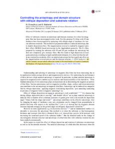
Johan Hoogboom,{* Theo Rasing, Alan E. Rowan and Roeland J. M. Nolte* Received 25th July 2005, Accepted 2nd November 2005 First published as an Advance Article on the web 24th November 2005 DOI: 10.1039/b510579j From simple pocket calculators, to mobile telephones and LCD-TV, over the past few decades devices based on liquid crystal display technology have proliferated into just about all conceivable aspects of everyday life. Although used in cutting-edge technology, it is surprising that a vital part in the construction of such displays relies essentially on a process invented almost 100 years ago. This essential part, the alignment layer, dictates the macroscopic uniform alignment of liquid crystalline molecules (mesogens) near its surface. The current method for manufacturing such layers is the mechanical rubbing of spin-coated polymers with a piece of velvet cloth. This very successful method is still at the basis of the production process of even the largest displays currently manufactured in industry. Unfortunately, the construction of ever larger displays with this technique is becoming a technological nightmare for engineers. Therefore, over the past decades, many alternatives to rubbing have been explored. This review will focus on advances towards achieving one of the most important goals in LCD technology: attaining rational control over the properties of nematic liquid crystal domains.
Organic Chemistry, Institute for Molecules and Materials, Radboud University Nijmegen, Toernooiveld 1, NL-6525ED, Nijmegen, The Netherlands. E-mail:
[email protected];
[email protected]; Fax: (+31)-24-2652929; Tel: (+31)-24-3652143 { This paper is partly based on a presentation given by R.N. at the ACS National Meeting, San Diego, CA, March 2005. { Current address: Department of Organic Chemistry, Massachusetts Institute of Technology, 77 Massachusetts Avenue, Bldg 18-143, Cambridge, MA, 02139, USA. E-mail:
[email protected]
substance was labelled a ‘‘living crystal’’. Years later, the official discovery of liquid crystals was credited to Otto Lehmann and Friedrich Reinitzer. In 1888, the Austrian chemist Reinitzer investigated the phase transitions of various compounds using a polarizing microscope fitted with a heating stage. Over the course of his study, Reinitzer discovered that cholesteryl benzoate changed from a clear to a cloudy liquid before crystallizing. Unfortunately, he attributed the apparent occurrence of two melting points to an imperfect phase transition. Still puzzled, a year later Reinitzer wrote a letter with his findings to the German physicist Otto Lehmann, who was an expert in crystal optics. After conducting similar experiments, Lehmann suggested that the cloudy fluid was a new phase of matter. Subsequently, in a landmark paper ¨ ber fliessende Krystalle’’, he described the disentitled ‘‘U covery of a class of crystals which were so soft that one could call them liquid, coining the term ‘‘liquid crystal’’.1 For several decades, liquid crystals were considered to be worthy of only scientific study, as they seemed to have little
Johan Hoogboom completed his PhD in supramolecular chemistry and solid state physics in 2004 at the Radboud University Nijmegen under the supervision of Roeland Nolte, Theo Rasing and Alan Rowan. He is currently a postdoctoral researcher at the Massachusetts Institute of Technology, Cambridge, USA, in the group of Timothy M. Swager. His research interests include the use of selfassembling systems to induce liquid crystal alignment and LCD-based biosensors.
Theo Rasing received his PhD from Nijmegen in 1982 on incommensurate crystals and worked at the University of California at Berkeley between 1982–1988. He is full professor in experimental physics at the Radboud University Nijmegen, working on the understanding and control of the relation between structure and properties of nanoscopic and molecular materials, with an emphasis on very small length scales (nm) and short time scales (fs).
Introduction From liquid crystals to LCDs The first observations of liquid crystalline behaviour, although not recognized as such at the time, were reported as far back as the 1850’s. Around that time, biologists Virchow, Mettenheimer and Valentin were studying nerve fibres. They found that a fluid substance from the nerve core, when left in water, exhibited strange behaviour if viewed in polarized light. Not recognizing the discovery of a new phase of matter, the
Johan Hoogboom
This journal is ß The Royal Society of Chemistry 2006
Theo Rasing
J. Mater. Chem., 2006, 16, 1305–1314 | 1305
Published on 24 November 2005. Downloaded by University of California - Santa Barbara on 04/01/2015 18:55:52.
View Article Online
merit with respect to industrial applicability. In fact, already before World War II, most scientists thought that the field of liquid crystals had matured and even been completed when a mathematical basis for the study of liquid crystals was provided by Oseen and Zocher.2 This all changed, however, in the sixties, when the liquid crystal display was invented. A crude display based on liquid crystals was first suggested by Richard Williams of RCA labs (Radio Company of America) in 1963 and developed into a device several years later.3 Unfortunately, his device required operating temperatures well above 100 uC. Because of this, its power consumption was too high and its display quality too low. The company soon developed mixtures that operated at room temperatures and continued research well into the seventies. A much improved version of the liquid crystal display, dubbed the twisted-nematic liquid crystal display, was developed by James Fergason of Kent State University, Ohio. It was patented in 1969 by his company ILIXCO, with the patent being applied in 1971.4 Its principle was described by Schadt and Helfrich,5a who applied their subsequent patent5b several months earlier than Fergason.5c Twisted-nematic liquid crystal displays The twisted-nematic liquid crystal display is still the most abundantly proliferated form of liquid crystal-based device. Vital to its operating principle were two independent observations on liquid crystalline behaviour. When combined, these two curiosities, as they were deemed at the time, formed the basis of liquid crystal display technology still employed today. The first discovery was reported as far back as 1911, when Mauguin had made several observations that liquid crystal domains could be aligned by placing them in contact with a crystal surface.6 Most brilliant, however, was his observation that if a liquid crystalline compound was placed between two aligning surfaces of different orientations, the director of the liquid crystalline compound (i.e. the average direction of the molecular axis of the mesogenic molecules in a domain) smoothly followed the transition, rotating from one surface to the other.6,7 Also, during World War II, Chatelain showed
Alan Rowan completed his PhD in physical organic chemistry in 1991 at the University of Liverpool, England. After a period of postdoctoral research at the University of Otago, Dunedin, New Zealand, he returned to Europe and became an assistant professor at the Radboud University Nijmegen in the group of Roeland Nolte. In 2004, he became a full professor in molecular materials. His scientific interests are the design and construction Alan Rowan of supramolecular assemblages possessing catalytic and electronic properties. Roeland Nolte received his PhD in physical organic chemistry 1306 | J. Mater. Chem., 2006, 16, 1305–1314
that liquid crystal compounds could be uniformly aligned by placing them between two glass plates and subsequently rubbing the plates along each other.8 The other discovery which contributed to the invention of the liquid crystal display was made by Freedericksz in the thirties. In elegant experiments, he showed that the orientation of liquid crystal molecules could be influenced by the application of an electric field.9 If the field strength was higher than a certain threshold value, the liquid crystal molecules would orient themselves with their dipoles parallel to the field, abandoning their previous orientation. In honour of its discoverer, such a transition is now called a Freedericksz transition. Engineers at that time, however, did not foresee any immediate applicability of these discoveries. This certainly changed when they were combined to construct the twistednematic liquid crystal display.4,5 Its operating principle is as brilliant as it is simple (Fig. 1). A liquid crystalline compound, usually a calamitic nematic liquid crystal, is sandwiched between two conductive surfaces—mostly indium-tin-oxide, ITO—covered with an alignment layer, which induces uniform planar alignment of the liquid crystal near the surface. Instead of orienting the alignment directions of the two surfaces in a parallel fashion, they are rotated 90u with respect to each other. As Mauguin showed, this prompts the director of the liquid crystal between the aligning surfaces to also rotate 90u going from one surface to the other (Fig. 1a). If the distance between the two plates is much larger than the wavelength of light transmitted through the cell, any incident light will also have its polarization direction rotated by 90u while traversing the cell.10 By adding polarizers to the cell, parallel to the liquid crystal alignment direction on their respective surfaces, a twisted-nematic liquid crystal cell is made which is capable of allowing light to pass crossed polarizers (off-state, Fig. 1a). This property can be switched by applying an electric field between the two conductive alignment layers. If the field strength exceeds the Freedericksz transition, the liquid crystal molecules will align parallel to the field direction (Fig. 1b). As the director of the liquid crystal no longer smoothly changes
from the University of Utrecht (1973), where he stayed and became assistant professor and then associate professor. In 1981, he was a visiting scientist at UCLA in the group of Donald J. Cram. In 1987 he moved to the Radboud University Nijmegen and became full professor of organic chemistry. Since 1994 he has also been a professor of supramolecular chemistry at the Eindhoven University of Technology. In 2003, the Roeland Nolte Royal Dutch Academy of Sciences awarded him an Academy Professorship. His principal research interest is supramolecular chemistry, focusing on the design of catalysts and molecular materials. This journal is ß The Royal Society of Chemistry 2006
Published on 24 November 2005. Downloaded by University of California - Santa Barbara on 04/01/2015 18:55:52.
View Article Online
Fig. 1 Operating principle of the twisted-nematic LCD; a) off-state; b) on-state.
between the two alignment surfaces, any incident light will not have its polarization direction altered. As such, it is no longer able to exit the cell through the second polarizer, which causes the cell to appear dark (on-state, Fig. 1b). When the electric field is switched off, the liquid crystal reverts back to its original structure and the cell is once again capable of transmitting light. The almost simultaneous development of micro-electronics in the sixties and seventies provided small switching elements, which could regulate the electric field strength in a single cell. When individual twisted-nematic cells, also called pixels, were connected in two-dimensional arrays, images could be produced by their coordinated switching, enabling the construction of liquid crystal displays.11 Liquid crystal alignment: rubbing One crucial element of the twisted-nematic liquid crystal display is the alignment layer, which is used to induce uniform and planar alignment of the liquid crystal molecules near the surface. Until the invention of the twisted-nematic cell, not much research had been done on the subject. Needless to say that the industrial production of this type of display spurred research into alignment surfaces.11a,12 Surprisingly, the process first applied to induce uniform alignment in the late sixties is very similar to the process used today. Simply called ‘‘rubbing’’, it had already been developed in the twenties.13 The method entails the unidirectional rubbing of a spin-coated polymer surface with a piece of cloth (Fig. 2a). As polymers, usually polyimides are used (Fig. 2b). Not only do they exhibit the thermal stability needed for application purposes, but they are also relatively cheap and easy to apply. In addition, their structure offers multiple possibilities for molecular interactions with the liquid crystal molecules in the display. The contact between the cloth and polymer layer creates microscopic grooves on the surface of the polymer (Fig. 2c) and aligns (substituents of) individual This journal is ß The Royal Society of Chemistry 2006
Fig. 2 a) Simplified representation of rubbing; b) polyimide Pyralin1-PI 2555; c) AFM image of a rubbed polyimide surface. Reused with permission from ref. 18c. Copyright 2001, American Institute of Physics; d) simplified representation of the alignment of liquid crystals on a rubbed surface.
polymer chains. When a liquid crystalline compound is interacted with such a surface, the mesogen adopts a macroscopic alignment (Fig. 2d). The alignment mechanism associated with rubbing has been debated for decades and can be roughly divided into two contributing components. The first component is a purely physical model, which holds that only the formation of microgrooves on the surface is responsible for liquid crystal alignment. The foundations of this theory were laid by Berreman, in his elastic continuum theory of 1972.14 In it, molecular interactions between the alignment layer and the liquid crystal molecules are assumed not to play a role in the alignment mechanism. Instead, the liquid crystal molecules orient themselves parallel to the microgrooves, which are formed as a result of the rubbing. The driving force for this is the minimization of the so-called elastic distortion energy. Simply put, this means that the alignment of liquid crystal molecules in and around the microgrooves, with their director parallel to the direction of the groove, results in the lowest surface energy and hence the most stable conformation (Fig. 3a).15 The other component is a molecular model, which holds that the factors responsible for alignment are mainly based on
Fig. 3 a) Berreman model of alignment; b) molecular model of alignment.
J. Mater. Chem., 2006, 16, 1305–1314 | 1307
Published on 24 November 2005. Downloaded by University of California - Santa Barbara on 04/01/2015 18:55:52.
View Article Online
molecular interactions. First suggested by Geary,16 this theory has recently won ground with other experimental confirmations.17 The theory hinges on the notion that individual polymer chains and/or their substituents are aligned by the unidirectional rubbing of the sample. This results in an ordered surface which is capable of engaging in anisotropic molecular interactions with liquid crystal molecules in the vicinity (Fig. 3b). This causes the unidirectional alignment of the first layers of liquid crystal molecules, after which the liquid crystal bulk follows epitaxially. Research into the mechanism of liquid crystal alignment has intensified over the past decades and has led to a significant increase in the understanding of the factors underlying liquid crystal alignment on ordered surfaces. For polymercoated surfaces, the current consensus is that the predominant alignment mechanism can be ascribed to the generation of a statistically important number of similarly oriented bonds in the top layer of the polymer,18a,c as described by the molecular model of alignment (vide supra). Another vital property of the alignment layer is the ability to induce a tilt in the liquid crystal molecules near the surface. Also called the pretilt angle, this quantity is responsible for the uniform texture of the liquid crystal display during operation.11b A detailed discussion, however, is beyond the scope of this review. The rubbing technique has several important advantages. It is relatively straightforward, easy and cheap. In addition, the resulting alignment surfaces are very stable and the techniques are already widely applied in industry.18a,b There are, however, also some serious drawbacks associated with this technique, which are all the result of the direct contact between the alignment layer and the velvet cloth during manufacturing.18a,19 For instance, the rubbing creates debris, which remains on the alignment layer and interferes with uniform liquid crystal alignment. In addition, as parts of the layer are rubbed off, the contrast ratio differs from site to site. Furthermore, the rubbing of the two materials creates electrostatic charges, which interfere with the switching of the display and destroy electronic circuits. All these drawbacks result in the creation of faulty pixels. In order to minimize the harmful effects of these drawbacks, the entire process is performed in a clean room, devoid of dust and charges, making this a very labour-intensive process. Also, as the need for larger displays is increasing, e.g. with the onset of large LCD-TV, the process requires ever more scaling up. Although factories are currently capable of processing plates of more than 4 m2, building a rubbing machine for even larger substrates, as demanded by market pressure, would be ‘‘a nightmare for engineers to build and operate’’.19 As such, research into novel ways of aligning liquid crystals has become increasingly important over the past decades.
Chart 1
problems associated with rubbing (vide supra). The molecules which are employed in this technique invariably contain double bonds, e.g. azobenzenes (Chart 1), which can be isomerized with light. Early work on photoalignment conducted in the seventies mainly focused on the disruption of an already present (aligned) mesophase when the chromophore dissolved in it in small quantities underwent a shape change going from the trans- to the cis-conformation during irradiation.21 In effect, the photoisomerization caused a phase transition of the liquid crystal medium in the LCD, which enabled the switching between two states with different mesogenic orientations, resembling the operating principle of twisted-nematic displays (Fig. 4). Upon irradiation with the proper wavelength(s) of polarized light, azobenzenes dissolved in a liquid crystal medium undergo a trans–cis isomerization, followed by (fast) thermal relaxation, until the dipole of the double bond is perpendicular to the polarization direction of the incident light, which occurs after about 10 minutes. This results in a cooperative, uniform alignment of both the chromophores and mesogens. At higher irradiation times, another process becomes dominant: optical pumping. As irradiation is sustained, the concentration of the less stable cis-form will increase with time. The shape change upon going from trans to
Alternatives to rubbing Photoalignment One of the most studied alternatives for rubbing is the photoalignment technique, which provides directional control over mesogens using polarized light.20 As such, this is a completely non-contact technique, eliminating most of the 1308 | J. Mater. Chem., 2006, 16, 1305–1314
Fig. 4 Operating principle of one of the first photoaligned displays (see text).
This journal is ß The Royal Society of Chemistry 2006
Published on 24 November 2005. Downloaded by University of California - Santa Barbara on 04/01/2015 18:55:52.
View Article Online
Fig. 5 Effect of irradiation of a chromophore-containing surface with linearly polarized light (out-of-plane reorientation or command surface effect).
cis is rather drastic, with the latter possessing a small cavity (Fig. 4). In addition, the cis-form has more affinity for the surface of the cell than the trans-form. The combination of these two effects causes the alignment of the mesogens in the direction parallel to the cell walls (Fig. 4). In 1991, Gibbons et al. used this principle to construct the first photoaligned LCD with a rewritable surface ordering.22 Another type of photoaligned display based on azobenzenes was developed by Ichimura et al. in 1988.20a,23 Instead of using the photochromic molecule as a dopant, it was chemoor physisorbed to the surface of the display. The switching of these tethered azobenzenes by polarized light also induced a change in the ordering of the mesogens, going from homeotropic to planar alignment (out-of-plane reorientation, Fig. 5). Because of their ability to switch the orientation of mesogens, these surfaces were named ‘‘command surfaces’’. Dependent on the type of azobenzene used, the switching time and interaction between surface and mesogen could be controlled.24 Azobenzene-tethered command surfaces are capable of two types of photo-reorientation of mesogenic molecules. Besides the out-of-plane reorientation shown in Fig. 5, the surfaces are also capable of inducing in-plane reorientations of mesogens (Fig. 6). The double bond of an azobenzene only stops isomerizing when its dipole moment is perpendicular to the polarization of the incident light. This implies that a rotation of the polarization direction of the incident light will entail the reorientation of the azobenzenes on the surface. In turn, the mesogenic molecules will follow the newly written order, which causes controllable in-plane movements of the mesogens (Fig. 6).20 Unfortunately, all the systems based on azobenzenes showed one major drawback: they were not stable. Due to random cis–trans relaxations and in-plane thermal motions, the written surface ordering was lost over a period of time, varying from seconds to months. Several methods were devised to stabilize the ordering. For instance, the use of a smectic liquid crystal instead of a nematic one allowed imprinting of the surface ordering of the azobenzenes into the smectic phase,
Fig. 6 Effect of changing the polarization direction of incident light on liquid crystal alignment (in-plane reorientation).
This journal is ß The Royal Society of Chemistry 2006
after which cooling the phase to below the Tg (the temperature below which the system is thermally stable) would preserve the image.20a,25 The technique, however, was deemed too laborious and prone to errors. This left most azobenzene-based systems ill-suited for practical applications, which spurred research into other types of photoalignment (vide infra). Recently though, several azobenzene-based systems have been reported which can be switched between two stable photoinduced states, which might be used in future devices.26 One of the first alternatives to azobenzenes were molecules based on cinnamic acid. In contrast to azobenzenes, these molecules exhibit two distinct photo-induced processes (Scheme 1). Besides the photo-induced trans–cis and cis–trans isomerizations and thermal relaxations, these molecules are capable of undergoing [2+2] photocycloaddition reactions upon irradiation with UV light. By irradiating a spin-coated layer of poly(vinyl-p-methoxycinnamate) with polarized (UV) light, Schadt et al. were able to create an alignment layer for LCD purposes.27 This landmark paper led to a boom in photoalignment research, which resulted in numerous papers and patents on the subject.28 Although the actual mechanism behind the alignment of liquid crystals in photoaligned systems is still under some debate, increasingly more insight has been attained into the two photochemical processes occurring during photoinduced ordering and their influence on mesogenic ordering. Drevensˇek Olenik et al. showed that the interaction between liquid crystal molecules and photoaligned cinnamoyl-containing alignment layers is mainly governed by the p–p interactions between the mesogens and the trans-cinnamoyl groups.28e In addition, photocycloaddition occurs preferentially between cis-cinnamoyl groups, resulting in the truxilate structure depicted in Scheme 1.28e,g These results imply a decrease of the interaction energy (also called anchoring energy) between the liquid crystal molecules and the surface during irradiation, as the photoprocesses entail a depletion of the trans-species. As such, the final surface ordering and its stability are provided by
Scheme 1 Schematic representation of the photochemistry of cinnamoyl derivatives.
J. Mater. Chem., 2006, 16, 1305–1314 | 1309
Published on 24 November 2005. Downloaded by University of California - Santa Barbara on 04/01/2015 18:55:52.
View Article Online
Scheme 2
Photoisomerization of: a) a-hydrazono-b-ketoesters; b) spiropyran–merocyanine systems.
two separate effects. First, the photocycloaddition provides a rigid framework to stabilize the ordering induced by mainly the trans-conformation of the cinnamoyl derivative. Second, the photocycloadduct itself is a source of surface ordering, as one isomer is preferentially formed. Besides derivatives of cinnamic acid, various other molecules containing a double bond have been used in the construction of photoaligned LCDs, e.g. a-hydrazonob-ketoesters29 (Scheme 2a) which are thermally stable at low operating temperatures due to intramolecular hydrogen bonding, and spiropyran–merocyanine systems30 (Scheme 2b), which might be used in devices. One other breakthrough in photoalignment was reported in 1996 by Schadt et al., who used a spin-coated polymer containing a coumarin-type dye (Chart 2).31 The irradiation of these polymers under an angle with respect to the surface resulted in the formation of an alignment layer which, when used in an LCD, offered a much improved field of view, compared to cinnamates.
This ordering effect could be attributed to two competing processes, which occur simultaneously. The first process is related to the large p-surface of 1, compared to similar cinnamates. As a result of this large p-surface, the compound oligomerizes in solution, forming rigid cyclic and linear oligosiloxanes (Fig. 7a). As the oligomer grows, it becomes increasingly less soluble, resulting in its precipitation. The second process involves the covalent grafting of these
Chart 3
Hierarchical rubbing Another alternative to rubbing, based solely on hierarchical self-assembly processes from solution, was reported by us in 2003.32 When an ITO plate was immersed into a solution of the naphthalene-functionalized siloxane 1 (Chart 3), an alignment surface was generated without the use of external stimuli (e.g. rubbing or photoalignment).
Chart 2
1310 | J. Mater. Chem., 2006, 16, 1305–1314
Fig. 7 Schematic representation of the construction of an LCD with a self-assembled alignment layer; a) oligomerization of 1; b) covalent grafting of oligomers of 1 to the ITO-surface containing nanogrooves, thereby amplifying their ordering over several orders of magnitude; c) interaction of the alignment layer with liquid crystals; d) LCD construction. Reproduced with permission from ref. 32. Copyright Wiley-VCH 2003.
This journal is ß The Royal Society of Chemistry 2006
Published on 24 November 2005. Downloaded by University of California - Santa Barbara on 04/01/2015 18:55:52.
View Article Online
Although photoalignment remains the most well-studied alternative to rubbing, during the past decades several other promising techniques have been developed. For instance, the group of Abbott reported a method for controlling the alignment of liquid crystals by using gold-sputtered plates covered with a self-assembled monolayer (SAM) of chemisorbed thiols (Fig. 8).33 They elegantly showed that the alignment properties of the layer could be fine-tuned by changing the deposition conditions and nature of the thiol.33a The latter was varied by using thiols with different alkyl tails. Experiments revealed an odd–even-effect of the length of the alkyl tail on the alignment properties. When odd-numbered alkyl tails were used, the liquid crystal molecules would align parallel to the surface, but perpendicular to the direction of the deposition of the gold layer (Fig. 8a). In contrast, when even-numbered alkyl tails were used, liquid crystal molecules would align parallel to both the surface and deposition direction of the gold layer (Fig. 8b). When a mixture of evenand odd-numbered tails was used, the liquid crystal molecules adopted a homeotropic orientation (Fig. 8c). Usually,
alignment layers based on gold are not suited for application purposes, as they are opaque to visible light. Abbott et al. were able to overcome this drawback by using thin gold sputtered ˚ thick.33a Although these layers were layers of around 100 A capable of transmitting incident light, they still displayed a poor maximum transmission, preventing their use in industrial manufacture.34 Bastiaansen et al. have recently overcome this ˚ thick, problem by using an ultra-thin gold layer of 1–100 A which decreased the light absorption and shifted the absorption band of the gold layer into the UV.34 In 2001, a group led by Chaudhari of IBM showed that liquid crystal alignment could be achieved by the bombardment of a carbonaceous surface with a low-energy ion beam at a glancing angle.35 By linearly moving the surface in front of an argon-sputtering gun, they were able to create an alignment layer without the use of a polymer. In pilot-line manufacturing, this method has already yielded 15- and 22-inch displays for laptop and desktop computers. The same year, Sto¨hr et al. were able to explain the results obtained by Chaudhari. They showed that the directional sputtering of argon ions caused the scission of only certain surface bonds, leaving a surface with a directional molecular bond order.36 In fact, they showed that any orientational bond order on a surface is capable of inducing liquid crystal alignment, which had been suggested before by Lee,37 and is in agreement with the proposed alignment mechanism on (rubbed) polymer substrates (vide supra). One other interesting technique is the modification of substrates with a tip from a scanning probe microscope, so-called ‘‘nanorubbing’’. Already in 1992, Majumdar et al. reproduced the surface characteristics generated by conventional rubbing, by scanning a gold-coated AFM-tip across a polymer layer.38 By applying a bias voltage between the surface and tip, the polymer could be burned away along the path of the tip. Several years later, Ruetschi et al. and Pidduck et al. showed that similar results could be obtained by mechanical scratching of a spin-coated polymer layer with an AFM tip (Fig. 9).39 Consequently, these systems were shown to be able to align liquid crystals.39,40 In addition, it was shown that scratches made on a bare ITO-surface were also capable of inducing liquid crystal alignment, eliminating the use of a polymer alignment layer.15a Although it is unlikely that the process could be scaled up to magnitudes which are of interest
Fig. 8 Schematic depiction of the effect of different thiol-containing SAMs on liquid crystal alignment; a) alkylthiols with an oddnumbered aliphatic tail cause alignment perpendicular to the deposition direction of the gold layer; b) alkylthiols with an even-numbered aliphatic tail cause alignment parallel to the deposition direction of the gold layer; c) a mixture of alkylthiols with odd- and even-numbered alkyl tails causes homeotropic alignment. The deposition direction of the gold layer is indicated by the arrows.
Fig. 9 SEM micrograph of spin-coated poly(methylmethacrylate) (Mw = 335 000) scratched with an AFM tip. Bar = 1 mm.
precipitating oligosiloxanes onto the ITO-surface (Fig. 7b). By very carefully tuning the rates of both processes, i.e. by ensuring that oligomers with the right size precipitate and graft at the right time during layer formation, a highly ordered surface could be constructed, which was shown to be capable of inducing uniform surface alignment of liquid crystalline molecules (Fig. 7c). These self-assembled alignment surfaces could be used in the construction of standard twisted-nematic LCDs (Fig. 7d) and rivalled industrially manufactured displays in terms of interaction energy between the alignment layer and the liquid crystalline matrix. Surprisingly, the overall direction of the surface ordering—and hence the liquid crystal alignment—was determined by the ITO plate, which was shown to contain parallel groove-like structures of nano-sized dimensions, which formed during its manufacturing. During the self-assembly process, the size and ordering of these nanogrooves was amplified over several orders of magnitude. The whole process could be performed under laboratory conditions, eliminating the need for clean-room facilities in alignment layer construction. Other techniques
This journal is ß The Royal Society of Chemistry 2006
J. Mater. Chem., 2006, 16, 1305–1314 | 1311
View Article Online
orientations of liquid crystalline molecules, e.g. planar or homeotropic, including controllable tilt angles.43
Published on 24 November 2005. Downloaded by University of California - Santa Barbara on 04/01/2015 18:55:52.
Towards rational control over nematic domains
Chart 4
to industry, this method offers more control over the formation of microgrooves, facilitating research into the exact nature of alignment mechanisms.18c Recently, our group was able to solve a long-standing debate regarding the exact nature of isotropic–nematic phase transitions near different alignment surfaces, whilst simultaneously developing a method for constructing a stable, noncontact alignment layer. By applying a magnetic field of 20 T to a spin-coated polymer layer on ITO, we were able to clearly distinguish, for the first time, between bulk and surface effects in the IN-phase transition.41a Consistent with theoretical predictions, we showed that the phase transition is first order for weakly anchoring surfaces and continuous for strongly anchoring surfaces. We also showed that stable macroscopic alignment could be achieved and retained by using more moderate fields of 2 T and that the alignment was stable even after removal of the field, and during continuous switching of the cell at elevated temperatures.41b As such, low magnetic fields can be used to easily generate stable alignment surfaces in a completely non-contact way. Lastly, ordered thin films, e.g. Langmuir–Blodgett monolayers, have also been shown to induce liquid crystal alignment. First reported by Daniel et al. in 1985,42 this technique has been shown to be very successful in inducing various
Recently, we demonstrated that the hierarchical rubbing process described above can also be applied to other siloxane derivatives, and we developed a technique that enables us to not only rationally control, but also tune the properties and alignment of nematic domains.44 By incorporating the pyridine-functionalized siloxane 2 (Chart 4) in the deposition process, an alignment surface that contains metal binding sites was constructed. In a subsequent step, this alignment surface was used to template the epitaxial growth of highly ordered columnar aggregates of the metallated dye zinc phthalocyanine (ZnPc) from solution (Fig. 10a). The height of these aggregates could be controlled by varying the time of immersion of the surface into a phthalocyanine solution: from 25 nm after 30 minutes, to 50 nm after 3 hours. The surface-templated epitaxial growth of such structures has not been reported before for such phthalocyanines and could have applications in technologies which rely on ordered dye systems, e.g. solar cell technology.45 When used in an LCD, these ZnPc-functionalized surfaces were capable of inducing stable liquid crystal alignment. Strikingly, compared to plates without ZnPc, the domain size of the mesogen had increased five-fold (Fig. 10b,c). Furthermore, it was shown that the ordering of the alkyl tails of the ZnPc aggregates on the surface could be tuned by applying a shear force, resulting in controllable macroscopic alignment of LCDs constructed using such plates (Fig. 10c, inset). The anchoring energy, which is a quantitative measure of the interaction strength between the alignment layer and the mesogen,18a was found to be strongly dependent on the immersion time of the ITO plate into the ZnPc solution, and consequently the stack height. As such, this technique offers
Fig. 10 a) Schematic depiction of the epitaxial growth of ZnPc stacks, templated by an alignment layer containing 2, followed by the disruption of the aggregates by the addition of nitrogen-containing compounds. All bars are 1 mm; b–d) polarising micrographs of liquid crystal cells constructed using: b) a spontaneously formed layer containing 2; c) a layer with ZnPc stacks. Inset: liquid crystal texture after application of a shear flow; d) characteristic texture of a layer with ZnPc stacks during infusion of an amine in the direction of the arrow. The line is a guide to the eye. All polarizers at 45u, images are 600 6 400 mm, except the inset, which is 6 6 4 mm. Reprinted with permission from ref. 44. Copyright 2005, American Chemical Society.
1312 | J. Mater. Chem., 2006, 16, 1305–1314
This journal is ß The Royal Society of Chemistry 2006
Published on 24 November 2005. Downloaded by University of California - Santa Barbara on 04/01/2015 18:55:52.
View Article Online
direct control over the interactions between alignment layer and mesogen. The alignment properties of the ZnPc layers could be further influenced by the addition of molecules to the liquid crystalline matrix of the display, that are capable of coordinating to and subsequently dissolving the aggregates. Introducing micromolar or nanomolar amounts of amines (e.g. amino acids alanine and glycine, and several aliphatic amines), into the cell usually resulted in loss of alignment (Fig. 10d). A wave-front was seen traversing the cell, leaving a non-aligning layer without ZnPc behind (Fig. 10a). Surprisingly, by using nanomolar concentrations of pyridine, which coordinates more weakly than aliphatic amines, the alignment capability of the system was retained; the anchoring energy, however, was reduced by a factor of 2.5. These combined results clearly show that our methodology offers tunability of nematic domain properties.
Conclusion and outlook The growth of LCDs on the display market seems unstoppable. Already in 2002, the production of flat panel displays exceeded that of displays based on cathode ray tubes. By the end of next year, it is projected that 80% of all industrially produced displays will be flat-panel ones, comprising an estimated total revenue exceeding $9b in 2007.18a The rubbing process is still very much at the heart of LCD production, and will probably remain so in the near future, in view of the recent construction of plants such as the Philips LCD Plant 7 in Korea, which will be capable of processing substrates of 195 6 225 cm.46 This facility, once operational, is projected to supply the demand for LCD-TVs for years to come. That, however, does not in any way suggest that research into different alignment methods should be abandoned. No matter how technologically impressive Plant 7 is as an engineering marvel, it is still based on a process which we have only recently begun to understand on a molecular level, thanks mostly to fundamental research and an intensified cooperation between several disciplines, e.g. solid state physics, organic chemistry and polymer chemistry. If the need should arise for even bigger substrates, it is not at all clear whether the process could be scaled up to larger proportions, whilst continuing to produce economically viable products. So what is the outlook for the coming decades? In the coming years, polymer chemistry and supramolecular chemistry will play an increasingly important role in alignment layer research and development, through the synthesis of smart (block co-)polymers, which form patterns on a surface, either by programmed self-assembly or processing.47 Cast or processed from solution, they micro-phase separate on a surface. This spontaneous process creates high molecular ordering based on hierarchical processes and is by definition a non-contact procedure. By changing the properties of the individual blocks, it will be possible to attain rational control over their assembly properties and consequently the surface ordering. Although it remains unlikely that alternatives to rubbing will be implemented on an industrial plant scale in this decade, a smart business decision would be to have at least several alternatives ready before market pressures necessitate a This journal is ß The Royal Society of Chemistry 2006
new production process. Next to the business-end of the field, however, there should always be a scientific curiosity as to the exact nature of interactions between an alignment surface and molecules above it, and acquiring means of controlling them.
Acknowledgements The authors would like to thank Dr J. A. A. W. Elemans for fruitful discussions, Dr M. Behdani for experimental assistance, and the Dutch Technology Foundation STW (project NNS4857) for financial support.
References 1 O. Lehmann, Z. Phys. Chem., 1889, 4, 462. 2 (a) W. C. Oseen, Trans. Faraday Soc., 1933, 29, 883; (b) H. Zocher, Trans. Faraday Soc., 1933, 29, 945. 3 (a) R. Williams, Nature, 1963, 199, 4890, 273; (b) R. Williams, J. Chem. Phys., 1963, 39, 2, 384. 4 J. Fergason, U. S. Patent, 3 731 986, 1969. 5 (a) M. Schadt and W. Helfrich, Appl. Phys. Lett., 1970, 18, 127; (b) W. Helfrich and M. Schadt, Br. Patent, 1 372 868, 1971; (c) The Story of Liquid Crystal Displays and the Creation of an Industry, ed. J. A. Castellano, World Scientific, Hackensack, NJ, 2005. 6 (a) C. Mauguin, Bull. Soc. Fr. Mineral., 1911, 34, 71; (b) C. Mauguin, Compt. Rend., 1913, 156, 1246. 7 C. Mauguin, Phys. Z., 1911, 12, 1011. 8 P. Chatelain, Bull. Soc. Fr. Mineral., 1943, 66, 105. 9 V. Freedericksz and V. Zolina, Trans. Faraday Soc., 1933, 29, 192. 10 C. Mauguin, Bull. Soc. Fr. Mineral., 1911, 34, 6. 11 (a) M. Schadt, Annu. Rev. Mater. Sci., 1997, 27, 305; (b) Liquid crystal displays: addressing schemes and electro-optical effects, ed. E. Lu¨der, Wiley, Chichester, 2001. 12 J. Cognard, Mol. Cryst. Liq. Cryst., Suppl. Ser., 1982, 1, 1. 13 H. Zocher, Naturwissenschaften, 1925, 13, 1015. 14 D. W. Berreman, Phys. Rev. Lett., 1972, 28, 1683. 15 (a) M. Behdani, A. Rastegar, S. H. Keshmiri, S. I. Missat, E. Vlieg and T. Rasing, Appl. Phys. Lett., 2002, 80, 24, 4635; (b) M. Behdani, S. H. Keshmiri, S. Soria, M. A. Bader, J. Ihlemann, G. Marowsky and T. Rasing, Appl. Phys. Lett., 2003, 82, 16, 2553. 16 J. M. Geary, J. W. Goodby, A. R. Kmetz and J. S. Patel, J. Appl. Phys., 1987, 62, 4100. 17 (a) N. J. A. M. van Aerle and A. J. W. Tol, Macromolecules, 1994, 27, 6520; (b) J. Sto¨hr and M. G. Samant, J. Electron Spectrosc. Relat. Phenom., 1999, 98–99, 189; (c) S. W. Lee, B. Chae, B. Lee, W. Choi, S. B. Kim, S. I. Kim, S.-M. Park, J. C. Jung, K. H. Lee and M. Ree, Chem. Mater., 2003, 15, 3105; (d) B. F. MacDonald, W. Zheng and R. J. Cole, J. Appl. Phys., 2003, 93, 8, 4442; (e) S. W. Lee, B. Chae, H. C. Kim, B. Lee, W. Choi, S. B. Kim, T. Chang and M. Ree, Langmuir, 2003, 19, 8735. 18 For an excellent overview covering recent breakthroughs in the understanding of liquid crystal alignment, see: (a) Surfaces and interfaces of liquid crystals, ed. T. Rasing and I. Musevic, Springer, Heidelberg, 2004; (b) Alignment technologies and applications of liquid crystals, ed. K. Takatoh, M. Hasegawa, M. Koden, N. Itoh and R. Hasegawa, CRC Press, London, 2005; (c) A. Rastegar, M. Sˇkarabot, B. Blij and T. Rasing, J. Appl. Phys., 2001, 89, 2, 960. 19 J. van Haaren, Nature, 2001, 411, 29. 20 (a) Photo-reactive materials for ultrahigh density optical memory, ed. M. Irie, Elsevier, Amsterdam, 1994; (b) T. Ikeda, J. Mater. Chem., 2003, 13, 2037; (c) K. Ichimura, Chem. Rev., 2000, 100, 1847. 21 (a) E. Sackmann, J. Am. Chem. Soc., 1971, 93, 7088; (b) W. E. Haas, K. F. Nelson, J. E. Adams and G. A. Dir, J. Electrochem. Soc., 1974, 121, 1667. 22 W. J. Gibbons, P. J. Shannon, S.-T. Sun and B. J. Swetlin, Nature, 1991, 351, 49. 23 K. Ichimura, Y. Suzuki, T. Seki, A. Hosoki and K. Aoki, Langmuir, 1988, 4, 1214. 24 (a) L. Komitov, C. Ruslim, Y. Matsuzawa and K. Ichimura, Liq. Cryst., 2000, 27, 1; (b) L. Komitov, K. Ichimura and A. Strigazzi,
J. Mater. Chem., 2006, 16, 1305–1314 | 1313
View Article Online
25
Published on 24 November 2005. Downloaded by University of California - Santa Barbara on 04/01/2015 18:55:52.
26
27 28
29 30
31 32 33
34
Liq. Cryst., 2000, 27, 51; (c) C. Ruslim and K. Ichimura, Macromolecules, 1999, 32, 4254. (a) K. Aoki, T. Seki, Y. Suzuki, T. Tamaki, A. Hosoki and K. Ichimura, Langmuir, 1992, 8, 1007; (b) K. Aoki, T. Tamaki, T. Seki, Y. Kawanishi and K. Ichimura, Langmuir, 1992, 8, 1014. (a) T. Masuda, M. Azuma, H. Ooshima, S. Tamagaki and T. Nagasaki, Chem. Lett., 2000, 872; (b) M. Kurihara, T. Matsuda, A. Hirooka, T. Yutaka and H. Nishihara, J. Am. Chem. Soc., 2000, 122, 12373; (c) D. Raghunath Reddy and B. G. Maiya, Chem. Commun., 2001, 117. M. Schadt, K. Schmitt, V. Kozinkov and V. Chigrinov, Jpn. J. Appl. Phys., 1992, 31, 2155. For a small selection, see e.g.: (a) G. P. Ryan-Brown and I. C. Sage, Liq. Cryst., 1996, 20, 825; (b) J. Liu, X. Liang and H. Gao, Jpn. J. Appl. Phys., 2000, 39, 1211; (c) J. L. Lenhart, J. H. van Zanten, J. P. Dunkers and R. S. Parnas, Langmuir, 2000, 16, 8145; (d) K. Ichimura, Y. Akita, H. Akiyama, K. Kudo and Y. Hayashi, Macromolecules, 1997, 30, 903; (e) I. Drevensˇek Olenik, M. W. Kim, A. Rastegar and T. Rasing, Phys. Rev. E, 1999, 60, 3, 3120; (f) I. Drevensˇek Olenik, M. W. Kim, A. Rastegar and T. Rasing, Phys. Rev. E, 2000, 61, 4, R3310; (g) M. W. Kim, A. Rastegar, I. Drevensˇek Olenik and T. Rasing, J. Appl. Phys., 2001, 90, 7, 3332; (h) A. Rastegar, M. W. Kim, I. Drevensˇek Olenik, P. de Witte, R. Nolte and T. Rasing, Mol. Cryst. Liq. Cryst., 2000, 351, 169; (i) R. Shashidhar, B. Peek, B. R. Ratna, J. M. Calvert, J. M. Schnur, M.-S. Chen and R. J. Crawford, U. S. Patent, 5 578 351, 1996; (j) K. Ogawa, T. Ohtake and T. Nomura, Jpn. J. Appl. Phys., 2000, 39, 5904; (k) H.-W. Gu, P. Xie, D.-Y. Shen, P.-F. Fu, J.-M. Zhang, Z.-R. Shen, Y.-X. Tang, L. Cui, B. Kong, X.-F. Wei, Q. Wu, F.-L. Bai and R.-B. Zhang, Adv. Mater., 2003, 15, 16, 1355; (l) S. Yamaki, M. Nakagawa, S. Morino and K. Ichimura, Macromol. Chem. Phys., 2001, 202, 325; (m) J. Naciri, J. Y. Fang, M. Moore, D. Shenoy, C. S. Dulcey and R. Shashidhar, Chem. Mater., 2000, 12, 3288; (n) J. Y. Fang, M.-S. Chen and R. Shashidhar, Langmuir, 2001, 17, 1549. P. Courtot, R. Pichon and J. Le Saint, Tetrahedron Lett., 1976, 1177 and 1181. (a) T. Sasaki and T. Ikeda, J. Phys. Chem., 1995, 99, 13013; (b) H. Sakamoto, M. Tanaka and K. Kimura, Chem. Lett., 2000, 928; (c) R. Wirnsberger, B. J. Scott, B. F. Chmelka and G. D. Stucky, Adv. Mater., 2000, 12, 19, 1450; (d) H. Nishikiori, R. Sasai, N. Arai and K. Takaoki, Chem. Lett., 2000, 1142. M. Schadt, H. Seiberle and A. Schuster, Nature, 1996, 381, 212. J. Hoogboom, M. Behdani, J. A. A. W. Elemans, M. A. C. Devillers, R. de Gelder, A. E. Rowan, T. Rasing and R. J. M. Nolte, Angew. Chem., Int. Ed., 2003, 42, 1812. (a) V. K. Gupta and N. L. Abbott, Science, 1997, 276, 1533; (b) K. G. Vinay and N. L. Abbott, Phys. Rev. E, 1996, 54, R4540; (c) K. G. Vinay and N. L. Abbott, Langmuir, 1996, 12, 2587; (d) R. A. Drawhorn and N. L. Abbott, J. Phys. Chem., 1995, 99, 16511. H. T. A. Wilderbeek, F. J. A. van der Meer, K. Feldmann, D. J. Broer and C. W. M. Bastiaansen, Adv. Mater., 2002, 14, 9, 655.
1314 | J. Mater. Chem., 2006, 16, 1305–1314
35 P. Chaudhari, J. Lacey, J. Doyle, E. Galligan, S.-C. Lien, A. Callegari, G. Hougham, N. D. Lang, P. S. Andry, R. John, K.-H. Yang, M. Lu, C. Cai, J. Speidell, S. Purushothaman, J. Ritsko, M. Samant, J. Sto¨hr, Y. Nakagawa, Y. Katoh, Y. Saitoh, K. Sakai, H. Satoh, S. Odahara, H. Nakano, J. Nakagaki and Y. Shiota, Nature, 2001, 411, 56. 36 J. Sto¨hr, M. G. Samant, J. Lu¨ning, A. C. Callegari, P. Chaudhari, J. P. Doyle, J. A. Lacey, S. A. Lien, S. Purushothaman and J. L. Speidell, Science, 2001, 292, 2299. 37 B.-W. Lee and N. A. Clark, Science, 2001, 291, 2576. 38 A. Majumdar, P. I. Oden, J. P. Carrejo, L. A. Nagahara, J. J. Graham and J. Alexander, Appl. Phys. Lett., 1992, 61, 19, 2293. 39 (a) M. Ruetschi, P. Grutter, J. Funfschilling and H. J. Guentherod, Science, 1994, 265, 512; (b) A. J. Pidduck, S. D. Haslam, G. P. Bryan-Brown, R. Bannister and I. D. Kitely, Appl. Phys. Lett., 1997, 71, 2907. 40 (a) C. L. H. Devlin, S. D. Glab, S. Chiang and T. P. Russell, J. Appl. Polym. Sci., 2001, 80, 1470; (b) J.-H. Kim, M. Yoneya, J. Yamamoto and H. Yokoyama, Nanotechnology, 2002, 13, 133. 41 (a) M. I. Boamfa, M. W. Kim, J. C. Maan and T. Rasing, Nature, 2003, 421, 149; (b) M. I. Boamfa, S. V. Lazarenko, E. C. M. Vermolen, A. Kirilyuk and T. Rasing, Adv. Mater., 2005, 17, 5, 610. 42 F. C. Saunders, J. Staromlynska, G. W. Smith and M. F. Daniel, Mol. Cryst. Liq. Cryst., 1985, 122, 1–4, 287. 43 (a) A. Lu, H. Deng and Y. Wei, Supramol. Sci., 1998, 5, 649; (b) V. S. U. Fazio, L. Komitov and S. T. Lagerwall, Liq. Cryst., 1998, 24, 3, 427; (c) H. Ikeno, A. Oh-Saki, M. Nitta, N. Ozaki, Y. Yokoyama, K. Nakaya and S. Kobayashi, Jpn. J. Appl. Phys., 1988, 27, 4, L475; (d) J. Y. Fang, Z. H. Lu, G. W. Ming, Z. M. Ai, Y. Wei and P. Stroeve, Phys. Rev. A, 1992, 46, 8, 4963. 44 J. Hoogboom, P. M. L. Garcia, M. B. J. Otten, J. A. A. W. Elemans, J. Sly, S. V. Lazarenko, T. Rasing, A. E. Rowan and R. J. M. Nolte, J. Am. Chem. Soc., 2005, 127, 31, 11047. 45 L. Schmidt-Mende, A. Fechtenko¨tter, K. Mu¨llen, E. Moons, R. H. Friend and J. D. MacKenzie, Science, 2001, 293, 1119. 46 http://www.lgphilips-lcd.com. 47 (a) V. Vorflusev and S. Kumar, Science, 1999, 283, 1903; (b) S. Walheim, E. Scha¨ffer, J. Mlynek and U. Steiner, Science, 1999, 283, 520; (c) M. Park, C. Harrison, P. M. Chaikin, R. A. Register and D. H. Adamson, Science, 1999, 276, 1401; (d) M. Bo¨ltau, S. Walheim, J. Mlynek, G. Krausch and U. Steiner, Nature, 1998, 391, 877; (e) S. Zhu, Y. Liu, M. H. Rafailovich, J. Sokolov, D. Gersappe, D. A. Winesett and H. Ade, Nature, 1999, 400, 49; (f) A. M. Higgins and R. A. L. Jones, Nature, 2000, 404, 476; (g) S. O. Kim, H. H. Solak, M. P. Stoykovich, N. J. Ferrier, J. J. de Pablo and P. F. Nealey, Nature, 2003, 424, 411; (h) E. W. Edwards, M. F. Montague, H. H. Solak, C. J. Hawker and P. F. Nealey, Adv. Mater., 2004, 16, 15, 1315; (i) M. P. Stoykovich, M. Mu¨ller, S. O. Kim, H. H. Solak, E. W. Edwards, J. J. de Pablo and P. F. Nealey, Science, 2005, 308, 1442.
This journal is ß The Royal Society of Chemistry 2006