Learning Action Plans in a Virtual Environment 1
Simon Goss Air Operations Division Defence Science and Technology Organisation (DSTO) Aeronautical and Maritime Research Laboratory GPO Box 4331, Melbourne, Victoria, 3001, Australia
[email protected]
Adrian Pearce School of Computer Science Curtin University GPO Box 1987U, Perth, WA, 6845, Australia
[email protected]
Keywords Agents, Virtual Environment, User Interface, User Intention, Simulation, Plan Recognition.
1
Draft, appears in In L. Hettinger and M. Haas, editors,Virtual and Adaptive Environments. Lawrence Erlbaum Associates, Inc., 2003.
Overview of Chapter An operator in a virtual environment generally has a purposeful motivation in undertaking activity. This can range from task-focused activity in a vocational sense, such as telepresence surgery or rehearsing mission tactics in a flight simulator, to the purely recreational exploration of a cyberspace. The design of such virtual interfaces is human-centered, in that the intentionality of the user is supported within the environment according to what they want to do. An adaptive virtual interface is explored, that monitors the user, and compares user behaviors to models of possible actions and intentions. We present a method for constructing that describe action plans of agents and entities in a virtual environment, using belief, desire and intentionality-based reasoning. These are required for testing candidate operator intentions against operator action history, to establish the validity of what happens in operational simulations. This is demonstrated experimentally in the context of flight simulation, and we present a method for learning action plans in real-time. Three components are required: an appropriate ontology (model of operator task performance), a virtual environment architecture (accessibility of data and image generation databases) and a machine learning and matching procedure (that relates the data stream to the domain ontology). The simulator is enhanced to provide descriptions of the out-the-window worldview in the data trace as well as operator control actions and simulation internal state variables. Machine learning methods are subsequently applied to traces of pilot behavior during flight
tasks,
in
real-time.
Introduction
An operator in a virtual environment generally has a purposeful motivation in undertaking activity. This can range from task-focused activity in a vocational sense, such as telepresence surgery or rehearsing mission tactics in a flight simulator, to the purely recreational exploration of a cyberspace. The design of such virtual interfaces is human-centered, in that the user is supported within the environment according to what they want to do. All of these use the computer as a transformative technology for immersion.
The cockpit and computer screens become the
experience of flying; the gloves and the screen put the surgeon's hand in the digital patient of an anatomy trainer. Furthermore, the same interface may provide an augmented reality in the actual environment such as the surgeon performing telepresence surgery, or in the electronic cockpit where alternate sensor views are superposed in a fused information device to assist with traversal of physical space and the avoidance of real physical threats. Particular information is required at particular times in response to particular contingencies, and the display device filters and shapes the information appropriately for the context.
Our view is that facilitating human-centered design in the adaptive virtual interface is about recognising intentionality of the user. An intention of such a user can be defined as follows (Tidhar et. Al, 1999): An intention is the commitment of an agent to achieve a goal by progressing along a particular future path that leads to the goal.
Design choice constrains the affordances offered by the virtual environment interface. For our purposes, a virtual interface requires an explicit representation of intentionality in the internal representation of agent implementation. We subscribe to the folk psychologic belief, desire and intentionality notion of agency in the construction of an interface agent, and in its interpretation of
the actions of entities in the virtual environment. Here, an agent emulates rational behavior in that it has intentions which it forms according to its beliefs and goals. An agent uses pre-defined plans, which are applicable to the situation, to fulfil its intentions (long term persistent goals). Such an agent is differentiated from an object-oriented entity in that it is reflective rather than immediately reactive to environmental sensor input. For a description of the agent formalism see (Georgeff & Lansky, 1986; Rao & Georgeff, 1991).
An intention-facilitating virtual interface recognizes the plans of the user. The level of delegation and authority given to the interface agent (assistant, associate or even supervisor) in taking actions having recognized the plans of the system user by observation of the user’s actions and the sensed environment is a current issue in system construction. (For example in the degree of delegation given to the virtual personal assistant in communication space, or the amount of autonomous authority given to an electronic crew member embedded in the avionics of the cockpit of the future. (Miller & Goldman, 1997). The interface agents need to recognize the situation and service the user intentions; all require recognition of intention of the user. Rao and Murray, working in the domain of pilot agents in an operations research simulation system, indicated that one way to implement recognition is to introspect upon one’s own behavioral repertoire (the plans one knows about ) and ascribe these to other agents (Rao & Murray, 1994). Intention recognition becomes a search through plan space for plans which match the observed actions of the other entity. This has been demonstrated in a limited capacity in a prototype system (Tidhar & Busetta, 1996) that shows a dramatic change of outcome when agents reason about what other agents might be doing. In military simulations where agents provide artificial players problems of coordination (Tambe et al., 1995) have been found to be due to failure to recognize intentional situations in teams (Kaminka & Tambe, 1997; Tambe, 1997).
The (non-trivial) issue confronting model-based planning systems as interface agents is the recognition of plans of the user whilst in execution. The problem is harder than identifying an action upon its completion. To be of practical assistance an interface agent needs to know what is happening before that event is over. We explore this in the context of flight simulation, and present a method for learning action plans from spatio-temporal data which describe action plans of agent/entities in a virtual environment. These are required for testing candidate operator intentions against operator action history, and are interpretable as partial instantiations of (operator/agent) intentionality.
Our method of constructing procedures requires three components: (a) an appropriate ontology (model of operator task performance), (b) an appropriate virtual environment architecture (accessibility of data and image generation databases), and (c) a learning procedure (which relates the data stream to the domain ontology).
In simple terms, we are looking at the domain of circuit flight. When learning to fly, student pilots use a set of rules to determine when to perform certain manoeuvres, such as described in a typical flying training manual (Thom, 1993): “A medium level turn from down-wind leg onto base leg is made when the touchdown point on the runway lies approximately 30 degrees behind … In a strong wind the turn should be commenced earlier to keep the base-leg closer to the aerodrome boundary.” A student pilot will frequently look over their shoulder, judging the angle to the runway and guessing the moment to turn. This often takes considerable cognitive effort on the part of the pilot requiring considerable attention. As the pilot become more experienced these rules – whilst still valid – tend to be lost in the sub-conscious and the pilot just knows when to
commence the turn. The pilot perceives the spatial relationships within their field of view and turns without even being aware of the angles between their aircraft and the runway.
The flight simulator has an authentic flight model for a PC9 aircraft, and a cockpit with generic throttle and stick controls. It also has a particular software architecture conferring special data recording properties. A relational learning technique is used to relate the data from the flight simulator to the operator ontology. We build relations which describe generalized flight plan segments.
In practice these run in real time and announce attributed plan segments while the pilot is executing them. This is a compelling demonstration of the feasibility of real-time recognition of intention in a user interface to an immersive virtual environment task. We assert that our results have wider significance and may form part of the foundation for the construction of agentoriented simulations, and more broadly, virtual environments
Ontology Acquisition In order to recognize the intentions of the user across the virtual interface we need to understand the activities the user is undertaking. To relate plan level description of pilot activities to the detailed data observable in the world of the flight simulator requires explicit representation of the activity goal structure. An ontology is a set of terms, their definitions, and axioms relating them; terms are normally organized in a hierarchy (Noy & Hafner, 1997). involves task analysis and knowledge engineering.
Ontology acquisition
Simple methods were used: consulting
training materials used by a flight instructor, interview of a flight instructor and a contrived method (Schvaneveldt, 1990; Schvaneveldt, Durso, Goldsmith, Breen, & Cooke, 1985) which
used pair-wise comparison of terms obtained from an aviation psychologist to construct a knowledge network. The results of each were used to construct a task hierarchy for concept demonstration purposes of the recognition of intention.
Pilot skills are comprised of hierarchic competencies. Some of these involve the ability to recover from abnormal situations. Our design choice of an agent-oriented implementation of the interface agent views these as a nested hierarchy of goals. The training method involves acquisition of concepts then application of the skills these describe to build , first a set of part task skills, then more complex combinations and refinements of these. This process is paralleled in the machine learning method here where a domain ontology is acquired, then procedural ontological elements acquired.
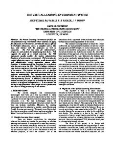
Pilots first learn the effects of the controls, taxiing, straight and level flight, climbing descent and turning (level, ascending, descending and to selected headings). Stalls are practiced mainly as a preventative measure. Competency must be demonstrated in recognition and recovery from stalls and incipient spins. These are combined in the complex exercise of circuit flight. A circuit consists of four legs in a box shape, with the runway in the center of one of the long legs. Take off and landing are into the wind. After take off an aircraft climbs to a height of 500 ft above the aerodrome level. On the crosswind leg the aircraft climbs to 1000 ft above the aerodrome. Height is maintained at this level on the downwind leg which is parallel to the runway. The aircraft descends on the base leg to a height of 500-600 ft above aerodrome level and turns to fly the final leg directly along the line of the runway. This is shown in Figure 1. The Normal Circuit Pattern.
Competency must be demonstrated in a range of sequences. For example in a Cross-Wind leg, although the wind may be blowing straight down the runway during the take-off, winds can change without notice.
Downwind Leg
1000ft Above Aerodrome Level Downwind Leg
5-600ft Base Leg Take Off
Final Leg
Windsock
5-600ft
Figure 1: The normal circuit pattern is flown at 1000ft above aerodrome level.
Other tasks are learned once the pilot has achieved first solo prior to graduating as a pilot: steep turns ( which require a different control strategy); recovery from unusual attitudes, low level flight, forced landings without power, and formation flight (keeping station, change between formation patterns and to fly formation circuits).
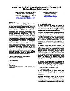
Our ontology is small and incomplete. We present it as a task hierarchy in Figure 2. Ontology is an arena in which psychology and computer science “interface”. Some elements are to be found
in the architecture of the simulator software and interface, some in the descriptions of activities in the simulator. For instance the ontology of circuit flight involves control actions to achieve navigation and flight control goals. These goals are part of the task hierarchy; the controls are part of the interface.
Flaps & Throttle Lift Off Take-off
Climb (Flaps) Climbing Turn Climb
Crosswind Leg Medium-Level Turn
Straight and Level Circuit Flight
Downwind Leg Medium Level-Turn Descend (No Flaps) Base Leg
Descend (Flaps) Medium Descending Turn Descend (Flaps)
Final Leg Descend (Full Flaps)
Landing
Round Out Touch Down
Figure 2: The circuit flight task hierarchy. Manoeuvres are represented as a hierarchy of manoeuvres and sub-manoeuvres or events. The abstraction possible in our FSIM demonstrator can be nested, providing a decomposition of manoeuvres and events. That is, to talk about the activity of compound entities you need to be able to explicitly represent the relationship between entities across the ontology.
There is the complication that contingency plans are executed in parallel, and that plans at several levels can be currently under execution and interleaved. For example the goals of safety are concurrent with goals of navigation and communication. In the implementation a blackboard system in which procedures sit and watch the input space in parallel is used. However the hierarchical representation of goals is useful for navigating the knowledge structure and organizing training sessions in the simulator.
The Virtual Environment Architecture. The architecture of the virtual environment constrains the interactional possibilities. Paraphrasing Boden, it is not how the world is, but how it is represented as being that is crucial with regard to the truth of intentional statements (Boden, 1978) . In order to make sense of the actions of the user, and of other virtual agents in the virtual environment in intentional terms we need to be able ask and answer questions of the environment. The architecture we describe arose from attempts to use flight simulators as knowledge acquisition tools to get rules of pilot performance with the eventual aim of creating agent rule bases to provide artificial agents as opponents and allies in human-in-the-loop simulation, and to represent crew behavior in the operations research models of air engagements. The insight driving this was that we can have access to the image generator object database and include in it labels for objects as well as rendering information for visual displays. We can then create a data record, on a frame by frame basis if required, which relates the user actions to symbol level descriptions of the virtual world presented to the user as imagery. This is the raw material of descriptions and perception of intentional acts in a virtual environment.
In addition to the status of navigation instruments and past actions, pilots use knowledge of the world, both in own-ship (egocentric or view-dependent) and map-view (exocentric or view-
independent) representations. Such information is critical in control and trajectory planning in the visual flight regime. We refined a workstation-based flight simulator used in machine learning of control strategies (Sammut, 1992) by rewriting it to provide the worldview and a high-fidelity dynamical flight model. Our flight simulator has a significant difference in veracity, interface and data architecture. It has the ability to not only record the actions of pilots, instrument and simulation internal status variables, but also dynamic knowledge of the world; the positions of objects, and dynamic entities in the three dimensional flight course relative to the pilot, and pilot motion (Goss, 1993; Goss, Dillon, & Caelli, 1996)
The flight controls for the simulator include a control column, throttle, brakes, rudder, and flaps, in a generic single-seat cockpit with rudder pedals, stick, throttle and stick mounted switches. The switches are used for viewpoint controls, the autopilot, and mode switching and cueing of the flight simulator software. The cockpit is trolley mounted with a seat. A monitor in the trolley is used for instruments. The out-the-window worldview is projected onto a wall in a darkened booth with a video projector. The simulator runs using (possibly many) video projectors in a projection room. (We are in fact using the work up and part-task psychometric simulator facilities of the Australian Defence Science and Technology Organisation (DSTO) Air Operations Simulation Center which has a variety of wheel-in cockpits for fixed and rotary-wing aircraft, and a variety of visual displays including helmet mounted displays and 200 degree by 100 degree partial dome). For remote demonstration purposes we have implemented a desktop flight simulator throttle and stick. The workstation monitor provides the out the window view. A Flybox provides throttle and stick and switches. A general view in the simulation community is that this level of interface is sufficient for ancillary players whose purpose is to provide agency for other players in the virtual environment such as wingmen or incoming targets for experimental subjects.
The
simulation center facility was most acceptable to pilots. There is also a mouse and keyboard interface. In each case we can monitor the control actions of the pilot.
The displayed instruments include airspeed, direction, an artificial horizon, rate of climb, throttle position, and flaps position indicators. Movement through the virtual environment is based on a six degrees of freedom flight model, which uses a database validated from wind-tunnel experiments. The flight model is authentic to a particular class of aircraft, in our case the PC9, a high performance single-engine propeller driven airplane.
We record the virtual world in our data structures and are able to relate operator activity to goals in the outside world. The main additional requirements to a typical flight simulator are for recording the visual and geographic positions of objects and to determine their visibility. We accomplish this with a Symbolic Description Generator (SGD), which is analogous in operation to the image generator in a virtual environment. Its function however is to render a description of the component of the scenery and their mutual relations rather than render the pixel image from the object database The SDG consists of two levels. The first generates raw data which describes the positions and visibility of target points on each object in the simulation. The second, and most important level, converts these data into a rich symbolic description of the visual scene. The simulated world is a large area containing natural features such as mountains and rivers, and cultural features like buildings and runways. Objects can be static or dynamic, such as moving vehicles. The world is described through a number of object databases which are loaded via a command file.
For recording descriptions of imagery, issues include the frame update rate and the rate of update of description. There are many permutations of imagery that would correspond to a single
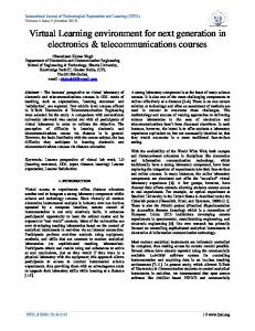
symbolic description. The scene description is insensitive to small changes in scale and ranging. The data-recording rate is variable, depending on the underlying hardware and the current scene complexity. Time is calculated in absolute terms, so a varying visual update rate does not affect the subsequent symbolic processing. Side, rear and map views are available, and viewing mode changes are also logged. The object database contains a set of objects, each of which may have a number of trackable or target points on them. These points are used to give quantitative relative relationships when referencing objects. For example, when referencing a mountain, it is useful to reference the peak of the mountain, a set of points around the base, and possibly the volumetric centroid of the mountain. Multiple target points on an object also allows the observation of higher order properties such as relative rotation of an object. The output is in the form of time-series relational statements, which can be illustrated with periodic in-place images as required. An example is shown in Figure 3. The symbolic statements refer to the visibility of objects, their spatial relations, their relationship to the center of visual flow (COVF), the pilot controls, and the absolute position of objects and the simulated aircraft. Each variable or variable pair can be controlled to different levels of quantization, or different thresholds for noticing change. The output can be in a linguistic variable form, or in a numeric form.
16.2: Control(Pilot,0,-245) 16.2: Position(Plane,-3205.6,5.1,-3975.0) RPY(Plane,0,357,90) 16.2: Thrust=10000.0 Rudder=0.0 Airspeed=98.6 Climb=31.6 16.2: Flaps=20 Gear(Down) Landed(No) Stalled(No) ....................................................................................... 18.1: 1 1 runway1:end viewable visible -2500.0 0.0 -3975.0 0.0 -17.6 18.1: Position(Plane,-3102.6,10.6,-3975.0) RPY(Plane,0,352,90) ....................................................................................... 18.6: 14 0 mountain2:centre viewable visible 1875.0 50.0 -5000.0 -15.7 -17.0 18.6: 16 0 mountain4:centre viewable visible 4050.0 58.3 -3800.0 1.8 -17.0 .......................................................................................
Figure 3: FSIM flight simulator trace. Top: The FSIM flight simulator is based on a PC9, high performance single-engine propeller driven aeroplane that utilises a wind-tunnel database plane model. The world and objects can be loaded in at run time and is displayed, including airspeed, direction, artificial horizon, rate of climb, throttle position and flaps position indicators. instruments. Bottom: The name and position of objects and entities with their relationships to the center of visual flow (COVF) are recorded along with control actions and aircraft status parameters.
Additional features of the system include an autopilot system that permits either direct implementation of a discrete time controller, or the integration of a machine learning system that uses previously recorded data to determine operational flight rules. A wingman view is available, suitable for flight replay or monitoring autopilot behavior. The design of the data record, the replay modes and the annotation facilities are significant design issues in the use of virtual environments as research environments.
Learning Plans In our flight simulator work we build on the work of Sammut and co-workers (Sammut, 1996; Sammut, 1992). Their work in machine learning concerned the construction of behavioral clones from traces of operator action on a workstation running a flight simulator program. A consensus view (generalization across a number of operator traces) is constructed as an autopilot. This autopilot can then fly the simulator. As it encompasses general tendencies rather than recording a particular episode it captures the underlying strategy and reduces the effect of episodic variation. The behavioral clone is a characterization of the control strategy of the operator at the task. This work represented a significant departure for machine learning from dealing with static data and classifier tasks.
From our point of view the ability to reproduce behavior is not the same as being able to recognize it. The data structures in the behavioral clone work loose information available in the external world. The subjects in the simulator are told to fly a flight plan with respect to features in the environment. The auto pilot rules are at the level of operation of control devices such as flaps and throttle. The research goal was to produce behavior. The outside world is referenced only indirectly in terms of distance from the origin of the Cartesian co-ordinate system set at the foot of
the runway. In Figure 4 an example of a rule controlling the throttle during ascent is shown, where Z_feet is the distance from the runway during approach to land.
Z_feet 30642 : | elevation > -43 : thrust_20 | elevation