We show how Logic Programming deduction and Neural Network learning can be inte- grated within the field of Neural-Symbolic Integration. In order to show ...
LEARNING AND DEDUCTION IN NEURAL NETWORKS AND LOGIC
A thesis submitted to the National University of Ireland, Cork for the degree of Doctor of Philosophy
Ekaterina Komendantskaya
Supervisor: Doctor Anthony Seda Head of department: Professor J¨ urgen Berndt
Department of Mathematics College of Science, Engineering and Food Science National University of Ireland, Cork
May 2007
ii
Table of Contents Abstract
vii
Acknowledgements
ix
Declaration
xi
Introduction
1
1 Logic Programming 1.1 Introduction . . . . . . . . . . . . . . . . . . 1.2 First-Order Language and Theory . . . . . . 1.3 Syntax of First-Order Logic Programs . . . . 1.4 Interpretation and Herbrand Interpretation . 1.5 Declarative Semantics and the TP operator . 1.6 Operational Semantics and SLD-Resolution 1.7 Conclusions . . . . . . . . . . . . . . . . . .
. . . . . . .
. . . . . . .
. . . . . . .
. . . . . . .
. . . . . . .
. . . . . . .
. . . . . . .
. . . . . . .
. . . . . . .
. . . . . . .
. . . . . . .
. . . . . . .
. . . . . . .
. . . . . . .
. . . . . . .
. . . . . . .
. . . . . . .
15 15 18 20 24 31 35 39
2 Many-Valued Logic Programming
41
3 Bilattice-Based Logic Programming 3.1 Introduction . . . . . . . . . . . . . . . . . . . . . . . . . . . . . 3.2 Bilattices . . . . . . . . . . . . . . . . . . . . . . . . . . . . . . 3.2.1 Basic definitions . . . . . . . . . . . . . . . . . . . . . . . 3.2.2 Interlaced and Distributive Bilattices . . . . . . . . . . . 3.3 First-Order Annotated Languages Based on Bilattice Structures 3.4 Interpretations . . . . . . . . . . . . . . . . . . . . . . . . . . . 3.5 Bilattice-Based Annotated Logic Programs . . . . . . . . . . . . 3.6 Unification . . . . . . . . . . . . . . . . . . . . . . . . . . . . . . 3.7 Conclusions . . . . . . . . . . . . . . . . . . . . . . . . . . . . .
49 49 53 53 58 69 75 84 89 92
iii
. . . . . . . . .
. . . . . . . . .
. . . . . . . . .
. . . . . . . . .
. . . . . . . . .
. . . . . . . . .
4 Declarative and Operational Semantics for Bilattice-Based Annotated Logic Programs 93 4.1 Introduction . . . . . . . . . . . . . . . . . . . . . . . . . . . . . . . . . . . 93 4.2 Declarative Semantics for Bilattice-Based Logic Programs (BAPs) . . . . . 96 4.2.1 Continuity of TP . . . . . . . . . . . . . . . . . . . . . . . . . . . . . 104 4.3 SLD-resolution for Bilattice-Based Logic Programs . . . . . . . . . . . . . 109 4.3.1 SLD-refutation for BAPs . . . . . . . . . . . . . . . . . . . . . . . . 110 4.3.2 Completeness of SLD-resolution for BAPs . . . . . . . . . . . . . . 120 4.4 Relation to other Kinds of Bilattice-Based Logic Programs . . . . . . . . . 126 4.5 Conclusions . . . . . . . . . . . . . . . . . . . . . . . . . . . . . . . . . . . 145 5 Neural Networks: Connectionism or Neurocomputing? 147 5.1 Introduction . . . . . . . . . . . . . . . . . . . . . . . . . . . . . . . . . . . 147 5.2 Neural Networks . . . . . . . . . . . . . . . . . . . . . . . . . . . . . . . . 154 5.2.1 Three-Layer Neural Networks . . . . . . . . . . . . . . . . . . . . . 157 5.3 TP -Neural Networks . . . . . . . . . . . . . . . . . . . . . . . . . . . . . . 159 5.3.1 Extensions of TP -Neural Networks: Outline of the Relevant Literature167 5.4 Learning in Neural Networks . . . . . . . . . . . . . . . . . . . . . . . . . . 170 5.4.1 Hebbian Learning . . . . . . . . . . . . . . . . . . . . . . . . . . . . 170 5.4.2 Error-Correction Learning . . . . . . . . . . . . . . . . . . . . . . . 171 5.4.3 Filter Learning and Grossberg’s Law . . . . . . . . . . . . . . . . . 173 5.4.4 Competitive Learning and Kohonen’s Layer . . . . . . . . . . . . . 174 5.5 Conclusions . . . . . . . . . . . . . . . . . . . . . . . . . . . . . . . . . . . 175 6 TP -Neural Networks for BAPs 6.1 Introduction . . . . . . . . . . . . . . . . . . . . . . . . . . . . 6.2 TP -Neural Networks for BAPs . . . . . . . . . . . . . . . . . . 6.3 Approximation of TP -Neural Networks in the First-Order case 6.4 Relation to other Many-Valued TP -Neural Networks . . . . . . 6.5 Conclusions . . . . . . . . . . . . . . . . . . . . . . . . . . . . 7 SLD Neural Networks 7.1 Introduction . . . . . . . . . . . 7.2 G¨odel Enumeration . . . . . . . 7.3 Unification in Neural Networks 7.4 SLD Neural Networks . . . . . . 7.5 Conclusions . . . . . . . . . . .
. . . . .
. . . . . iv
. . . . .
. . . . .
. . . . .
. . . . .
. . . . .
. . . . .
. . . . .
. . . . .
. . . . .
. . . . .
. . . . .
. . . . .
. . . . .
. . . . .
. . . . .
. . . . .
. . . . .
. . . . .
. . . . .
. . . . .
. . . . .
. . . . .
. . . . .
. . . . .
. . . . .
. . . . .
177 . 177 . 179 . 191 . 198 . 201
. . . . .
203 . 203 . 205 . 209 . 217 . 235
8 Conclusions and Further Work 237 8.1 Conclusions . . . . . . . . . . . . . . . . . . . . . . . . . . . . . . . . . . . 237 8.2 Further Work . . . . . . . . . . . . . . . . . . . . . . . . . . . . . . . . . . 240 Bibliography
243
v
NATIONAL UNIVERSITY OF IRELAND, CORK Date: May 2007 Author:
Ekaterina Komendantskaya
Title:
Learning and Deduction in Neural Networks and Logic
Department: Mathematics Degree: Ph.D.
Convocation: May
Year: 2007
Permission is herewith granted to National University of Ireland, Cork to circulate and to have copied for non-commercial purposes, at its discretion, the above title upon the request of individuals or institutions.
Signature of Author THE AUTHOR RESERVES OTHER PUBLICATION RIGHTS, AND NEITHER THE THESIS NOR EXTENSIVE EXTRACTS FROM IT MAY BE PRINTED OR OTHERWISE REPRODUCED WITHOUT THE AUTHOR’S WRITTEN PERMISSION. THE AUTHOR ATTESTS THAT PERMISSION HAS BEEN OBTAINED FOR THE USE OF ANY COPYRIGHTED MATERIAL APPEARING IN THIS THESIS (OTHER THAN BRIEF EXCERPTS REQUIRING ONLY PROPER ACKNOWLEDGEMENT IN SCHOLARLY WRITING) AND THAT ALL SUCH USE IS CLEARLY ACKNOWLEDGED.
vi
Abstract We show how Logic Programming deduction and Neural Network learning can be integrated within the field of Neural-Symbolic Integration. In order to show this, we combine methods of Connectionism and Neurocomputing. We introduce Bilattice-Based Annotated Logic Programs (BAPs) which are suitable for reasoning with uncertainty and incomplete/inconsistent databases. We propose a fixed-point semantics for them, and in particular, we propose a semantic operator capable of computing the least Herbrand models of BAPs as its least fixed points. We define an inference algorithm, called SLD-resolution, for BAPs and prove that it is sound and complete with respect to the fixed-point semantics. We show that the semantic operator for BAPs can be simulated in Connectionist Neural Networks that embed Hebbian Learning functions. The learning neural networks we construct improve computational complexity comparing with other classes of non-learning neural networks that simulate many-valued semantic operators. However, similarly to other Connectionist Neural Networks, in the case of first-order Bilattice-Based Annotated Logic Programs, this construction would require an infinite number of neurons in order to perform computations of the semantic operator. We prove an approximation theorem showing that finite neural networks can approximate such computations. Finally, we build artificial neural networks that perform the SLD-resolution algorithm for conventional Horn-clause Logic Programs. The resulting neural networks are finite and embed six learning functions. They can be practically implemented as a neural network interpreter for SLD-resolution. We conclude that the integrative approach using techniques from both Connectionism and Neurocomputing is very effective. We suggest further work to be done in this field. In particular, we outline possible future developments of the neural network interpreter for SLD-resolution.
vii
viii
Acknowledgements I am grateful to my supervisor, Dr Anthony Seda, for organising the work of the research group “Nature Inspired Models of Computation” and for his supervision of my PhD studies. I would also thank Dr Anthony Seda and Dr John Power for supervising the joint research project “Category Theory and Nature Inspired Models of Computation” between the universities of Cork and Edinburgh. This project had an immense influence on my research. I thank Dr John Power for very useful discussions on various topics. Two Schools for Postgraduate Students MATHLOGAPS (Mathematical Logic and Applications), University of Leeds, August 2006, and MODNET (Model theory), University of Leeds, December 2005, helped me to form a very general understanding of major techniques and problems solved in Mathematical Logic. It is my pleasure to thank Dr Jim Grannell, the chairman of the School of Mathematics, Applied Mathematics and Statistics, University College Cork, for generous funding of my visits to Leeds; and Professor Dugald MacPherson, School of Mathematics, University of Leeds, for organising the splendid training courses for PhD students. I thank Dr Roy Dyckhoff for his useful suggestions concerning my work, and in particular, for his useful comments concerning the first three chapters of this thesis. I am also grateful to Dr Dyckhoff for organising a splendid academic visit for me at the School of Computer Science, University of St Andrews in January 2007. The summary of some of our January discussions constituted the Further Work section of the thesis. I thank Dr Damien Woods for supplying me with up-to-date references concerning complexity characterisation of neural networks. I thank the School of Mathematics, Applied Mathematics and Statistics, University College Cork, for the tuition bursary I was offered for the time of my studies in Cork. Apart from providing funding, this gave me valuable experience of teaching mathematics at university level. ix
I thank the Boole Centre for Research In Informatics, University College Cork, for funding the second year of my PhD studies and for partial funding of my visits to conferences. I acknowledge the “Fee-Waiver for Non-EU Nationals” scholarship provided by the Postgraduate Studies Board, University College Cork. Several different organisations funded my visits to international conferences, and I acknowledge their kind support: the American Association for Symbolic Logic (ASL) grant for presenting a paper at CIE’06; travel grant from the Organisers of CIE’06, University of Swansea, Wales; student travel grant from the organisers of LATA’07, University of Tarragona, Spain. I thank Paul Keegan, the System Administrator in the School of Mathematics, UCC, for presenting me with a very reliable laptop. This gave me a happy chance to study at home when my daughter was born. Every line of this thesis and every line of each of my papers published while in Cork was typed on this laptop. I thank my husband, Dr Vladimir Komendantsky, for bringing me to Cork, and for encouraging me to start my PhD studies there. I am infinitely grateful to my mother, Anna Gubanova, and to my parents in law, Evgeniy Komendantsky and Zoya Komendantskaya, for jointly paying the fees for the first year of my studies in UCC. Without their support, my arrival in Cork would have never been possible. I am grateful to Martine Seda for her support and caring attention to me and all my family during the time of my studies in Cork. I thank all my office mates, and in particular M´aire Lane, Clodagh Carroll, Marina Yegorova-Dorman, Jackquie Kirrane, and Julie O‘Donovan, for creating the unique friendly and warm atmosphere in our office. Every day of my life, I thank my two Annas – my mother and my daughter — for loving me, for being with me, for being two symmetric parts of my heart. Cork
Ekaterina Komendantskaya
x
Declaration This thesis was composed by myself and the work reported in it is my own except where otherwise stated.
xi
xii
Introduction “The human mind... infinitely surpasses the powers of any finite machine”. This manifest by Kurt G¨odel, proclaimed in his Gibbs lecture to the American Mathematical Society in 1951, has been challenging researchers [21, 27, 149, 151] in many areas of computer science and mathematics to build a device that will prove to be as powerful as the human brain. The very titles speak for themselves: “A logical calculus of the ideas immanent in nervous activity”[151] (1944), “Probabilistic Logics and the Synthesis of Reliable Organisms from Unreliable Components”[165] (1956), “The Algebraic Mind”[149] (2001), “Brain Calculus”[27] (2001), “Brane Calculi”[21] (2004), this is just to mention some of the work done in this field. This fundamental problem of creating (and then evaluating) automated reasoning system based upon some formally defined logical calculus is, however, at least one century older than G¨odel manifest cited above. One can argue that the problem is as old as mathematical logic and even computational mathematics. Thus, a century before G¨odel, George Boole, one of the fathers of mathematical logic, was driven by the same problem of how one can formalise human reasoning, and his famous “An Investigation of the Laws of Thought on Which are Founded the Mathematical Theories of Logic and Probabilities” [18] is often cited as the first book on mathematical logic. Several years later, Peano [169] was trying to introduce a calculus capable of deriving 1
mathematically valid statements. Hilbert, in his attempts to find proper foundations of mathematics and a proper formal calculus for it, published “Axiomatic thought” [87] in 1918 and announced the programme of formalising mathematics using some logical calculus. This program is now commonly called “Hilbert’s Programme”. And thus, at the beginning of the 20th century, Mathematical Logic became an independent discipline of Mathematics. There were three results that determined the birth and development of the discipline: • The Completeness Theorem of G¨odel [1929] establishing that in first-order predicate calculus every logically valid formula is provable. • The Incompleteness Theorem of G¨odel [1931] showing incompleteness of any axiomatic arithmetic. More precisely, G¨odel proved that there are undecidable propositions in every axiomatic theory which is at least as rich as Peano Arithmetic. • The existence of algorithmically undecidable problems, in particular, the Theorem of Church [1936] about algorithmic undecidability of first-order predicate calculus and the equivalent theorem of Turing [1936] concerning undecidability of the halting problem for Turing machines. The three former results gave evidence that Hilbert’s programme cannot be accomplished. However, even after the famous theorems of G¨odel, Church and Turing, the major question of how one can create some kind of automated reasoning, or, as it was later called, artificial intelligence, remained as appealing as in the times of Boole. Turing’s machines stimulated the creation of digital computers; biology and neuroscience became proper scientific disciplines. And all this progress only increased interest in the general 2
problem of creating an artificial intelligence. Returning to the citation of G¨odel we started with, it is worth mentioning that, as advocated in [36], G¨odel specifically claimed that Turing, who created and promoted the use of Turing machines, overlooked that the human mind “in its use, is not static but constantly developing”. This particular concern of G¨odel found a further development in connectionism and neurocomputing [151, 164, 165, 83, 159, 179]. A very delicate discussion of G¨odel’s and Turing’s arguments, and of the general question of whether the human mind acts algorithmically, and whether the soundness of such algorithm would be provable, can be found in [171]. Connectionism is a movement in the fields of artificial intelligence, cognitive science, neuroscience, psychology and philosophy of mind which hopes to explain human intellectual abilities using artificial neural networks. Neural networks are simplified models of the brain composed of large numbers of units (the analogs of neurons) together with connections between the units and weights that measure the strength of these connections. Neural networks demonstrate an ability to learn such skills as face recognition, reading, and the detection of simple grammatical structure. We will pay special attention to one of the topics of connectionism, namely, the so-called topic of neuro-symbolic integration, which investigates ways of integrating logic and formal languages with neural networks in order to better understand the essence of symbolic (deductive) and human (developing, spontaneous) reasoning, and to show interconnections between them. Neurocomputing is defined in [85] as a technological discipline concerned with information processing systems (neural networks) that autonomously develop operational capabilities in adaptive response to an information environment. Moreover, neurocomputing is often seen as an alternative to programmed computing: the latter is based on the 3
notion of some fixed algorithm (a set of rules) which must be performed by a machine; the former does not necessarily require an algorithm or rule development. Note that in particular, neurocomputing is specialised on the creation of machines implementing neural networks, among them are digital, analog, electronic, optical, electro-optic, acoustic, mechanical, chemical and some other types of neurocomputers; see [85] for further details about physical realizations of neural networks. In this thesis we will use methods and achievements of both connectionism and neurocomputing: namely, we take the connectionist neural networks of [98, 99] as a starting point, and show how they can be enriched by learning functions and algorithms implemented in neurocomputing. We believe that this sort of synthetic methodology is novel in its own right, as we have found a gap between the methods of connectionism and neurocomputing. The two areas seem to be largely isolated at the moment. Thus, although learning functions are the main topic within Neurocomputing, the text book on neuro-symbolic integration entitled “Neural-Symbolic Learning Systems” [30] does not employ to any significant extent most of the learning functions used in Neurocomputing and surveyed in Section 5.4. From the side of Neurocomputing, one argues that nine-neuron networks are sufficient to simulate Universal Turing Machines [190], see also Section 5.1. From the side of NeuroSymbolic Integration, one approximates the work of infinite neural networks in order to simulate the Turing-computable least fixed points of the semantic operator TP for firstorder logic programs [98]. And this method of [98] has been developed for more than a decade, inspiring a number of papers about approximations of the infinite neural networks [99, 94, 10, 184]; see Chapter 5 and Section 6.3 for further details. The main question we address is: how can learning in neural networks and deduction 4
in logic complement each other? The main question splits into two particular questions: Is there something in deductive, automated reasoning that corresponds (or may be brought into correspondence) to learning in neural networks? Can first-order deductive mechanisms be realized in neural networks, and, if they can, will the resulting neural networks be learning or static? First we fix precise meanings of the terms “deduction” and “learning”. Deductive reasoning is inference in which the conclusion is necessitated by, or deduced from, previously known facts or axioms. The notion of learning is often seen as opposite to the notion of deduction. We adopt the definition of learning from neurocomputing, see [82]. Learning is a process by which the free parameters of a neural network are adapted through a continuing process of simulation by the environment in which the network is embedded. The type of learning is determined by the manner in which the parameter changes take place. The definition of the learning process implies the following sequence of events: • The neural network is stimulated by an environment. • The neural network undergoes changes as a result of this stimulation. • The neural network responds in a new way to the environment, because of the changes that have occurred in its internal structure. In this thesis we will borrow techniques from both supervised and unsupervised learning paradigms, and in particular we will use such algorithms as error-correction learning (see Section 5.4.2), Hebbian learning (see Section 5.4.1), competitive learning (see Section 5.4.4) and filter learning (see Section 5.4.3). 5
The field of neuro-symbolic integration is stimulated by the fact that formal theories (as studied in mathematical logic and used in automated reasoning) are commonly recognised as deductive systems which lack such properties of human reasoning as adaptation, learning and self-organisation. On the other hand, neural networks, introduced as a mathematical model of neurons in the human brain, are claimed to possess all of the mentioned abilities, and moreover, they provide parallel computations and hence can perform certain calculations faster than classical algorithms [190]; see also Section 5.1. As a step towards integration of the two paradigms, there were built connectionist neural networks [98, 99] which can simulate the work of the semantic operator TP for propositional and (function-free) first-order logic programs. These neural networks, however, were essentially deductive and could not learn or perform any form of self-organisation or adaptation. Moreover, in the first-order case, when the Herbrand base of a given logic can be infinite, the neural networks of [98, 99] would require an infinite number of neurons to compute the least fixed point of the semantic operator. This problem was tackled by proposing finite neural networks that approximate the computations performed in the infinite neural networks [94, 184, 10]. Therefore, there are at least two disconcerting conclusions that can be made about the construction of neural networks of [98, 99].
1. The first negative conclusion is that computations performed by the neural networks simulating TP do not require learning. This leads to a general conclusion that conventional logic, being implemented in neural networks, is incapable of showing any sort of learning or self-organisation. This conclusion is especially disconcerting, if we recall that one of the main benefits of neural networks that Neurocomputing is proud of is the use of learning. 6
2. The second conclusion concerns the very method of implementing logic in neural networks. The fact that infinite neural networks would be required to simulate the conventional semantic operator suggests that the method of building the neural networks is not optimal. Indeed, neural networks are, by definition, finite. (Although, similarly to the Turing machines, one can imagine them working for an infinitely long time and making infinitely many iterations.) So, the very notion of infinite neural networks violates the definitions and the common practice of neurocomputing. Moreover, finite neural networks in general were shown to be as powerful and effective as universal Turing machines [190]. However, the neural networks of [98, 99] were incapable of computing the least fixed point of the TP operator using a finite number of neurons and required approximations whereas this can be easily done using (finite) Turing machines.
In this thesis we tackled both of the listed problems. First we used extensive methods of improving the neural networks of [98, 99]. That is, first we relied on the methods of [98, 99], but tried to extend them to non-classical logic programs, hoping that this would bring learning into the picture. This extension was indeed useful in this respect, and allowed us to bring learning into neural networks. (See also Section 5.3.1 for an outline of other possible extensions of the neural networks of [98].) However, the resulting neural networks inherited the second of the two problems listed above, that is, they still required an infinite number of neurons in the first-order case. This is why we turned to the second, intensive, method of improving the neurosymbolic networks of [98, 99]. We completely abandoned the methods used in [98, 99] and built neural networks that simulate the work of SLD-resolution, as opposed to the simulation of the semantic operator in [98, 99]. It is worth mentioning here that the 7
problem of establishing a method of performing first-order inference in neural networks has been tackled by many researchers over the last 30 years; see [72, 188, 136, 95], for example. The resulting SLD neural networks that we obtained showed the following properties: they were inherently finite, and embedded six learning functions, some of which represented supervised, and some unsupervised learning. Therefore, these novel neural networks solved both of the main problems listed above. The structure of the thesis is as follows. Chapters 1 and 2 are expository, and are used to give basic definitions and introduce major techniques that we use in later sections. In Chapter 1 we give an introduction to conventional logic programming and discuss its model-theoretic and proof-theoretic properties, mainly following [138]. Thus, we define “first-order language and theory”, and give interpretations for the language. We then define conventional logic programming, its syntax and semantics. We outline the main methods and techniques that are used to characterise logic programs semantically and computationally. Namely, we define the semantic operator for logic programs, and show that it characterises models of logic programs. We outline the main definitions and results concerning SLD-resolution that is used to run logic programs. In Chapter 2 we discuss many-valued logic programming and the three main ways in which many-valued logic programs extend conventional logic programs. We discuss the nature and properties of many-valued interpretations. We also use this chapter to survey the relevant literature in the subject. In the remaining chapters we develop our Thesis concerning deduction and learning in logic and neural networks. Chapters 3, 4 are devoted to Bilattice-Based Annotated Logic Programs (BAPs) in 8
order to show, in Chapter 6, that the semantic operator for BAPs can be simulated by learning neural networks. Therefore, these chapters serve to support the extensive method of developing the neural networks of [99]. The extensive method was chosen to make use of some non-classical formal theory, similar to logic programs for reasoning with inconsistencies [107], for example, and adapt the connectionist neural networks of [98, 99] to these logic programs in order to investigate if this adaptation brings learning into the picture. We chose many-valued logic programs for this purpose. And in particular, we chose bilattices as a suitable structure in which to take interpretations for the logic programs. Bilattices were advertised in [65, 49, 50], as structures which are particularly suitable for formalising human reasoning and serving for different purposes of Artificial Intelligence. And so, we chose bilattices to underly the many-valued logic programs. In Chapter 3 we introduce BAPs, and in Chapter 4 we characterise them from the model-theoretic and proof-theoretic point of view. Namely, we define a semantic operator TP for them, give declarative and fixpoint semantics based on properties of TP , propose the method of SLD-resolution for these logic programs, and show that this SLD-resolution is sound and complete. The two Chapters 3 and 4 characterise BAPs as a very interesting class of logic programs, both from the mathematical and computational points of view. Mathematically, they turn out to be a very general formalism that allows us to handle uniformly different many-valued logic programs within the context of BAPs; see Section 4.4 for further discussions. Also, we show in Section 4.2 that they possess some non-trivial model-theoretic properties. Computationally, they provide a sound and complete proof procedure that logic programs of this generality [108] fail to provide, see Section 4.3. 9
In Chapter 5, we give a very broad introduction to the history, background definitions, and main problems of Neurocomputing and Connectionism. We outline the relevant literature in these two areas. In Chapter 6, we use BAPs and build neural networks in the style of [98, 99] to simulate the computations of the semantic operator TP . As we hoped from the start, the resulting neural networks embed learning functions. Thus, we show that the connectionist neural networks need to embed learning functions in order to reflect some non-trivial properties of TP and perform its iterations. We also show in Section 6.4 that some fragments of BAPs can be simulated by different, non-learning, neural networks of Lane and Seda, proposed in [135]. But the learning functions used in the neural networks that we build in Chapter 6 improve the time and space complexity of computations compared with the neural networks of [185, 135], see [119]. Also, the neural networks for BAPs turn out to be more expressive than the neural networks of [185, 135]. And this proves that in general, learning methods taken from Neurocomputing are well worth implementing in the area of neuro-symbolic integration. However, we were not completely satisfied with the obtained results, for two major reasons. The first, and the main, reason was that the neural networks we built in the style of [98, 99] inherited all the main characteristic properties (see Section 5.3) of the neural networks of [98, 99]. And in particular, in the first-order case the mentioned above neural networks would become infinite, and would require the use of some nonconstructive approximation theorem similar to the one we prove in Section 6.3. So, the neural networks we have constructed are still less effective than (finite) Turing machines which are capable of computing the least fixed point of TP . The second reason for our scepticism concerning the neural networks for BAPs was that 10
Section 6.4 provided evidence that, although learning improves the complexity of neural networks, it still can be avoided in favour of more bulky but non-learning networks. This is why, in Chapter 7, we propose a novel method of building neural networks that can perform the algorithm of SLD-resolution for classical neural networks. This method solves intensively both of the main problems we mentioned above. That is, the resulting neural networks are finite, and embed six learning functions recognised in neurocomputing. Thus, we show that both negative conclusions made from considering the neural networks of [98, 99] can be effectively solved: 1. We show that classical (conventional) deduction requires the use of learning when implemented in neural networks, and the learning functions play a crucial role in computations. For example, these learning functions characterise the unification algorithm as an adaptive process, and use competitive learning when choosing the next goal from a given list of goals in the process of refutation. 2. There exist finite neural networks that computationally characterise first-order deduction. These new conclusions provide us with non-trivial answers to the main question we posed at the beginning of the Introduction. We conclude the following: learning neural networks are shown to be able to perform deductive reasoning. On the other hand, the learning neural networks of Chapters 6, 7 are built to simulate their logic counterparts. This is why we can make the conclusion that both the semantic operator for BAPs and classical SLD-resolution bear certain properties which correspond to learning functions in neurocomputing. This conclusion sounds like an apology for symbolic (deductive) theories because it suggests that symbolic reasoning which we normally call “deductive” does not 11
necessarily imply the lack of learning and spontaneous self-organisation in the sense of neurocomputing. Practically, SLD neural networks provide us with an interpreter which is capable of performing first-order deduction in finite and learning neural networks. To summarise, the thesis contains the following novel methodological, theoretical and practical results. • The methodological novelty of the thesis is that we combine the methods of Connectionism and Neurocomputing, in that we make use of the learning techniques applied in Neurocomputing when developing Connectionist neural networks. In particular, the learning techniques surveyed in Section 5.4 have never been implemented in the field of Neuro-Symbolic Integration before. • Theoretically, we show that the common distinction deduction versus learning cannot be supported by neurocomputing, and we establish that the SLD neural networks performing classical SLD-resolution are inherently learning. Therefore, one can talk about learning in deduction, rather than learning versus deduction. • Practically, we propose finite neural networks that can run the SLD-resolution algorithm. This open problem has been tackled by many researchers over the last 30 years, [72, 188, 136, 95]. Due to their inherent finiteness, the SLD-neural networks are implementable and applicable in the area of automated reasoning. We outline future work to be done with this respect in Section 8.2. All the main results of the thesis were published and presented in international conferences. Thus, the contents of Chapter 3 first appeared in [129], and were presented at the 12
International Conference “First-Order Theorem Proving” (FTP’05), Koblenz, Germany. But this material was further refined in [119, 127, 128, 126, 127]; and especially [123]. The contents of Chapter 4 were published in [119, 127, 128, 126, 127, 123], and presented at the Fourth Irish Conference on the Mathematical Foundations of Computer Science and Information Technology (MFCSIT’06), Cork, Ireland. The material of Chapter 6 appeared in [120, 127, 119] and was presented at the International Conference Computability in Europe (CiE’06), Swansea, Wales. The main results of Chapter 7 appeared in [120, 122] and were presented during the 1st International Conference on Language and Automata Theory and Applications (LATA’07), Tarragona, Spain. There were results that we obtained while working on this thesis, but that are not included in the text of this thesis. This is done to keep the current text focused on the single subject that we announced in the title: “Learning and Deduction in Neural Networks and Logic”. Nevertheless, these “abandoned” papers influenced very much our progress and understanding of the subject we worked on, and so deserve to be mentioned in this introductory chapter. In [124], we developed non-Horn clause logic programs, and the results were presented at the 1st World Congress on Universal Logic (UNILOG-05), Montreux, Switzerland. In [121], [123] we obtained a many-sorted representation of many-valued logics and logic programs, and the results were presented at the Fourth Irish Conference on the Mathematical Foundations of Computer Science and Information Technology (MFCSIT’06), Cork, Ireland and the International Conference on Automated Reasoning with Analytic Tableaux and Related Methods, TABLEAUX’07, Aix en Provance, France. We briefly survey some of these results in Chapters 3 and 4. 13
Finally, our work within the project “Category Theory and Nature Inspired Models of Computation” between the universities of Cork and Edinburgh, was very exciting and inspiring, and the results will appear in [125, 118].
14
Chapter 1 Logic Programming
1.1
Introduction
Logic Programming is one of the major subjects of this thesis. In this Chapter we give an introduction to the subject. We will briefly outline the history of Logic Programming, then we will focus on the precise background definitions concerning Logic Programs; and, finally, we will use different sections of this chapter to survey the relevant literature on the topic. Logic Programming can be seen as a combination of two major trends. On the one hand, it is supported by logicians, whose research contributes to the Logic component of Logic Programming. The other area is developed by practical programmers, who rather emphasise the Programming part of it. This thesis tends to contribute to the former area: the author sees Logic Programming as a rightful successor and branch of mathematical logic as it was understood by its fathers Boole [18], Frege [57, 56], Peano [169], Hilbert [87, 88, 89, 90, 91, 92, 93], Gentzen [63], G¨odel [67], Turing [201], Kleene [111], Church [22]. So, we start this first chapter with a short survey of the history and range of problems 15
stated and solved in Mathematical Logic. This discusssion will help us to evaluate the contribution of Logic Programming and Connectionism to the subject. The first attempts to build formal mathematical theories were made by Boole [18], Frege [56, 57], Peano [169], Peirce [170] and some other mathematicians. The major goal was to establish solid mathematical foundations, and find axioms and inference rules sufficient for proving any mathematically valid proposition. It was hoped that these propositions could be proven automatically. This program was associated with the name of Hilbert [87, 88, 89, 90, 91, 92, 93] and was shown not to be accomplishable: Kurt G¨odel [66] showed that every sufficiently rich formal system, such as Peano Arithmetic, is not complete, that is, there are mathematically true statements which are not provable in the system. This result, together with the corresponding results of Church and Turing mentioned in the Introduction, raised a wide range of questions concerning computability/uncomputability, model properties, barriers of computations, adequacy of inference techniques, etc. that have been tackled by researchers for more than 70 years. Mathematical Logic has become a dynamically growing field of mathematics. Since it was established as an independent discipline, Mathematical Logic has developed different disciplines within itself; among them are Model Theory [148], Computability Theory (Theory of Recursion) [194], Proof Theory [175]; some disciplines of mathematics, such as Set Theory, Category Theory [146] (see also [8] for some discussion of relations between logic and category theory) or Type Theory [207, 150] are often seen as disciplines of Logic; see, for example, [14] for a wide range of Mathematical Logic Disciplines. Mathematical Logic has found numerous applications in Computer Science, see [102, 1]; and [132, 112] are good examples of such interdisciplinary research. This perfect match of Mathematical Logic and Computer Science gave birth to a new discipline, which 16
is now commonly called Theoretical Computer Science. Theoretical Computer Science has been extensively developed, and it includes various subjects, some of which did not necessarily originate in mathematical logic; for example, analysis of algorithms, semantics of programming languages, etc. Logic Programming is one of those subjects where Logic and Computing meet. The idea of formal logical inference, or deduction, formed the basis for creation of a universal programming language Prolog. It is significant that almost every field of Mathematical Logic has found its application within the theory of logic programming. Thus, Sections 1.4, 1.5 will give a model-theoretic account of logic programming, Section 1.6 and [155, 156, 158, 124] give its proof-theoretic account. A computability, or rather, complexity, analysis of logic programming is given in [40, 70], a categorical account of logic programming is given in [173, 110, 46, 125], and type theory was widely implemented in higher-order logic programming and λPROLOG, see, for example, [162, 158]. Before we continue discussions of current advances in Logic Programming, we must discuss in some detail its history and its background notions. Logic Programming as an independent field of research began in the early 1970s as a direct outgrowth of earlier work on logic, automated theorem proving and artificial intelligence. Constructing automated deduction system was and remains central to the aim of achieving artificial intelligence. Built upon work of Herbrand [86] in 1930, there was much activity in theorem proving in the early 1960’s by Prawitz [174, 175], Gilmore [64], Davis, Putnam [35] and others. These efforts culminated in 1965 with the publication of the landmark paper by Robinson [178], which introduced the resolution rule. Resolution is an inference rule which is particularly well-suited for automation on a computer. The credit for the introduction of logic programming goes mainly to Kowalski [131] 17
and Colmerauer [26], although Green [69] and Hayes [81] should be mentioned in this regard. The famous Warren Abstract Machine (WAM) proposed by Warren [206] is one of the famous early PROLOG compilers. In 1972, Kowalski and Colmerauer were led by the fundamental idea that logic can be used as a programming language. The acronym PROLOG (PROgramming in LOGic) was conceived, and the first PROLOG interpreter [26] was implemented in the language ALGOL-W by Roussel, in Marseille in 1972. The idea that first-order logic, or at least a substantial subset of it, could be used as a programming language was revolutionary because, until 1972, logic had only been used as a specification of declarative language in computer science. However, what [131] shows, is that logic has a procedural interpretation, which makes it very effective as a programming language. See also Section 1.6 and 4.3. Most current logic programming systems are resolution theorem provers. However, logic programming systems need not necessarily be based on resolution. They can be non-clausal systems with many inference rules [19, 79, 158, 156, 124]. But here we will work only with resolution-based logic programming systems. The remaining sections of this chapter present the basic concepts and results which constitute the theoretical foundations of logic programming. We discuss first-order syntax, theories, interpretations and models, unification and SLD-resolution. We refer to classical books on the subjects, such as [138], [197], [25].
1.2
First-Order Language and Theory
As we mentioned in the previous section, the very notion of a logic program was built upon the notions of a first-order language and a first-order theory. And so we start discussions of the syntax of Logic Programs with a brief outline of first-order languages and theories. 18
We refer to classical books on mathematical logic, such as [22, 43, 111, 138, 153, 189]. A first-order theory T consists of an alphabet A, a first-order language L, a set of axioms and a set of inference rules. The first-order language consists of the well-formed formulae of the theory. The axioms are a designated subset of well-formed formulae. The axioms and rules of inference are used to derive the theorems of the theory. Definition 1.2.1. We fix the alphabet A to consist of • constant symbols a1 , a2 , . . ., • variables x1 , x2 , . . ., • function symbols f1 , f2 , . . ., • predicate symbols Q1 , Q2 , . . ., • connectives ¬, ∧, ∨, also called negation, conjunction and disjunction. • quantifiers ∀, ∃ and • punctuation symbols “(”, “, ” “)”. We will sometimes denote finite sequences of symbols x1 , . . . , xn by x. We follow the conventional (inductive) definition of a term and a formula. Namely, every constant symbol is a term, every variable is a term, and if fi is a function symbol of arity n and t1 , . . . , tn are terms, then fin (t1 , . . . , tn ) is a term. Let Qni be a predicate symbol of arity n and t1 , . . . , tn be terms. Then Qi (t1 , . . . , tn ) is a formula (also called an atomic formula or an atom). If F1 , F2 are formulae and x are variables, then ¬F1 , F1 ∧ F2 , F1 ∨ F2 , ∀xF1 and ∃xF1 are formulae. 19
Definition 1.2.2. The first-order language L given by the alphabet A consists of the set of all formulae constructed from the symbols of the alphabet. Example 1.2.1. ∀x1 ∀x2 (Q1 (x1 , x2 ) ∨ ¬Q1 (x1 , x2 )) is a formula of the language L. The next several definitions serve to fix the conventional terminology for bound and free variables, closed and ground formulae. Definition 1.2.3. The scope of ∀x (respectively ∃x) in ∀xF (respectively ∃xF ) is F . A bound occurrence of a variable in a formula is an occurrence immediately following a quantifier or an occurrence within the scope of a quantifier, which has the same variable immediately after the quantifier. Any other occurrence of a variable is free. Definition 1.2.4. A closed formula is a formula with no free occurrences of any variable. Example 1.2.2. In Example 1.2.1 all the occurrences of all the variables are bound, so the formula ∀x1 ∀x2 (Q1 (x1 , x2 ) ∨ ¬Q1 (x1 , x2 )) is closed. The formula ∀x1 (Q1 (x1 , x2 )) contains one free variable x2 , and so it is not closed. Definition 1.2.5. A ground term is a term not containing variables. Similarly, a ground atom is an atom not containing variables. Definition 1.2.6. A literal is an atom or the negation of an atom. A positive literal is an atom. A negative literal is the negation of an atom. Now we are ready to define the syntax of logic programs.
1.3
Syntax of First-Order Logic Programs
Logic Programs are finite sets of clauses, that is, first-order formulae satisfying the following definition. 20
Definition 1.3.1. A closed formula of the form ∀x(L1 ∨ . . . ∨ Ln ), where each Li is a literal, is called a clause. Following classical books [25, 197, 138] on Logic Programming, we assume that each logic program contains a finite number of clauses. Note that even finite logic programs can have infinite models, and infinite search trees generated by SLD-resolution algorithm. From the point of view of implementations, the use of infinite sets of clauses is not practical, and would allow undersirable non-determinism in both model theoretical and proof theoretical characterisations of logic programs. In the subsequent sections, we will need some infinite constructions. Thus, we will discuss infinite sets of clauses when talking about models of logic programs. We will use, for example, the notion of a set ground(P ) of all ground instances of a logic program P . This will not contradict to our assumption about inherent finiteness of logic programs. Example 1.3.1. [138] The formula ∀x1 ∀x2 ∀x3 (Q1 (x1 , x3 ) ∨ ¬Q2 (x1 , x2 ) ∨ ¬Q3 (x2 , x3 )) is a clause. Throughout, we will denote the clause ∀x1 , . . . xn (A1 ∨ . . . ∨ Am ∨ ¬B1 ∨ . . . ∨ ¬Bk ), where A1 , . . . , Am , B1 , . . . , Bk are atoms and x1 , . . . xn are the variables occurring in these atoms, by A1 , . . . , Am ← B1 , . . . , Bk . Following traditional convention, we will call A1 , . . . , Am a consequent of the clause, and B1 , . . . , Bk an antecedent of the clause. In the subsequent chapters, we will work with a particular kind of clauses, called definite clauses. We define them as follows: 21
Definition 1.3.2. [138] A definite program clause is a clause of the form A ← B1 , . . . , Bn , which contains at most one atom in its consequent. A is called the head and atoms B1 , . . . , Bn are called the body of the program clause. Definition 1.3.3. A unit clause is a clause of the form A ←, that is, a definite clause with empty body. A definite goal is a clause of the form ← B1 , . . . , Bn , that is, a definite clause with empty head. Definition 1.3.4. [138] A definite program is a finite set of definite program clauses. We introduce here some examples of definite logic programs, which will be used as running examples throughout the thesis. Example 1.3.2. Consider the following logic program P1 , which determines, for each √ pair of integer numbers x1 and x2 whether x1 x2 is defined.
√ defined( x1 x2 ) ← even(x1 ), nonnegative(x2 ) √ defined( x1 x2 ) ← odd(x1 ) Let Q1 denote the property to be “defined”, (f1 (x1 , x2 )) denote
√
x1
x2 ; Q2 , Q3 and Q4
denote, respectively, the property of being an even number, nonnegative number and odd 22
number. Then the program above can be represented as follows: Q1 (f1 (x1 , x2 )) ← Q2 (x1 ), Q3 (x2 ) Q1 (f1 (x1 , x2 )) ← Q4 (x1 ) We will use the latter representation in the future. To work properly, this program should be enriched with the program which determines whether a given number is odd or even, we will not address this issue here, but remark that such program can be found, for example, in [197]. Example 1.3.3. [197] In this example we slightly abuse the notation, and use predicates “connected” and “edge” instead of symbols Q1 and Q2 fixed in Definition 1.2.1. Let GC (for graph connectivity) denote the logic program
connected(x1 , x1 ) ← connected(x1 , x2 ) ← edge(x1 , x3 ), connected(x3 , x2 ). This program can determine, for all nodes x1 and x2 , whether they are connected. We just need to add unit clauses describing a particular graph: edge(a1 , a2 ) ← edge(a2 , a3 ) ← .. .. And then the program will be able to answer queries of the form ← connected(a1 , a3 ) or ← connected(x1 , x2 ), given by definite goals. 23
Example 1.3.4. This is an example of a ground definite logic program, that is, a program that does not contain variables. Q1 (a1 ) ← Q2 (a1 ) ← Q3 (a1 ) ← Q1 (a1 ), Q2 (a1 )
Definition 1.3.5. A Horn clause is a clause which is either a definite program clause or a definite goal. Although syntactically we consider mainly definite logic programs and Horn clauses in this thesis, it is worth mentioning that there exist other classes of programs, with more complicated syntax; and we list some of them in Table 1.3.1.
Note that all these
languages can be seen as containing the logic of Horn clauses. Table 1.3.1 represents the most popular syntactical extensions of Horn Clauses, but it is also possible to talk about semantical extensions of logic programming, for example, we can talk about modal and multimodal Horn clauses [11], about the probabilistic languages which use Kolmogorov’s axioms describing probabilities [76, 44, 77, 167, 166]; or we can work with many-valued Horn clauses, as we do in Chapters 2, 3. In any case, because of its minimality, Logic Programming based on Horn clauses is fundamental for us.
1.4
Interpretation and Herbrand Interpretation
The declarative semantics of a logic program is given by the usual (model-theoretic) semantics of formulae in first-order logic. This section discusses interpretations and models, 24
Type
of
Program
Syntax
Example
Clauses Horn
clauses
(PROLOG) [131]
Unrestricted uses of {∧},
∀x(A0 ← A1 ∧ . . . ∧ An ).
but {∀, ←} are restricted to the top level only.
Normal
clauses
Unrestricted
uses
of
(PROLOG)
{∧, ¬}, but {∀, ←} are
[23, 137]
restricted to the top level
∀x(A0 ← ¬A1 ∧ . . . ∧ An ).
only. Clauses
(PRO-
LOG) [139, 138]
Unrestricted
uses
of
{∧, ¬, ∨, ←, ∀, ∃}.
∀x1 Q1 (x1 )
←
∃x2 (¬Q2 (x1 , x2 ) ∨ (Q3 (x2 ) ← Q2 (x1 , x2 )).
Hereditary rop
Har-
formulae
(λPROLOG)
Unrestricted {∀, ∧, ←}.
uses
of
Restricted
∀x1 (Q3 (x1 ) ← (∀x2 (Q3 (x2 ) ← Q2 (x1 , x2 )) ∧ Q1 (x1 )))
uses of {∃, ∨}.
[161, 154, 162] Lolli (a refinement
Unrestricted
of λPROLOG) [4]
{∀, ∧, ←, (}.
Linear
Unrestricted
Objects
(LO) [3, 80]
uses
of
∀x1 (Q3 (x1 ) ← (Q1 (x1 ) ( ∀x2 (Q3 (x2 ) ← Q2 (x1 , x2 )))).
uses
of
{∧, O}, but {∀, (} are
∀x(A0 ( A1 O . . .OAn ).
restricted to the top level only. Forum [157]
Unrestricted
uses
{∀, ∧, ←, (, O}.
of
∀x1 (Q1 (x1 )
(
∀x2 (((Q3 (x1 )OQ1 (x1 ))
←
Q3 (x2 )) ← Q2 (x1 , x2 ))).
Table 1.3.1: Syntactical Extensions of Horn-Clause Logic Programming 25
concentrating particularly on the important class of Herbrand interpretations. First-order logic provides methods for deducing the theorems of a theory. These can be characterised, by G¨odel’s completeness theorem [67, 153], as the formulae which are logical consequences of the axioms of the theory, that is, they are true in every interpretation of the theory. In the logic programming systems which we are going to consider the resolution rule is the only inference rule. We fix the definitions of pre-interpretation, interpretation and model, they are standard and can be found in [138, 153, 22], for example. Definition 1.4.1. A pre-interpretation for a first-order language L consists of the following: • A non-empty set D, called the domain of the pre-interpretation. • For each constant of L, the assignment of an element in D. • For each n-ary function symbol in L, the assignment of a mapping from Dn to D. Definition 1.4.2. An interpretation I for a first-order language L consists of a pre-interpretation J with domain D of L together with the following: For each n-ary predicate symbol in L, the assignment of a mapping from Dn into {true, false}. Definition 1.4.3. Let J be a pre-interpretation for a first-order language L. A variable assignment (with respect to J) is an assignment to each variable in L of an element in the domain of J. Definition 1.4.4. Let J be a pre-interpretation with domain D for a first-order language L and let V be a variable assignment. The term assignment (with respect to J and V ) of the terms in L is defined as follows: 26
• Each variable is given its assignment according to V . • Each constant is given its assignment according to J. • If t01 , . . . , t0n are the term assignments for t1 , . . . , tn and f 0 is the assignment of the n-ary function symbol f , then f 0 (t01 , . . . , t0n ) is the term assignment for f (t1 , . . . , tn ). Definition 1.4.5. Let J be a pre-interpretation of a first-order language L, V be a variable assignment with respect to J, and A an atom. Suppose A is Q1 (t1 , . . . , tn ) and d1 , . . . , dn in the domain of J are the term assignments for t1 , . . . , tn with respect to J and V . We call AJ,V = Q1 (d1 , . . . , dn ) the J-instance of A with respect to V . Let {A}J = {AJ,V : V is a variable assignment with respect to J}. Definition 1.4.6. Let I be an interpretation with domain D of a first-order language L and let V be a variable assignment. Then a formula in L can be given a truth value true or false, as follows: • If the formula is an atom Q(t1 , . . . , tn ), then the truth value is obtained by calculating the value of Q0 (t01 , . . . , t0n ) where Q0 is the mapping assigned to Q by I and t01 , . . . , t0n are the term assignments for t1 , . . . , tn with respect to I and V . • If the formula has the form ¬F , F ∧ G, F ∨ G, then the truth value of the formula is given by the following table: F
G
¬F
F ∧G
F ∨G
true
true
false
true
true
true
false
false
false
true
false
true
true
false
true
false
false
true
false
false
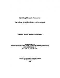
27
• If the formula has the form ∃xF , then the truth value of the formula is true if there exists d ∈ D such that F has the truth value true with respect to I and V (x/d), where V (x/d) is V except that x is assigned d; otherwise its truth value is false. • If the formula has the form ∀xF , then the truth value of the formula is true if, for all d ∈ D we have that F has the truth value true with respect to I and V (x/d); otherwise its truth value is false. Definition 1.4.7. Let I be an interpretation for a first-order language L and let F be a formula in L. We say F is satisfiable in I if ∃(F ) is true with respect to I. We say F is valid in I if ∀(F ) is true with respect to I. We say F is unsatisfiable in I if ∃(F ) is false with respect to I. We say F is nonvalid in I if ∀(F ) is false with respect to I. Definition 1.4.8. Let I be an interpretation for a first-order language L and let F be a closed formula of L. Then I is a model for F if F is true with respect to I. Example 1.4.1. Consider the formula ∀x1 ∃x2 Q1 (x1 , x2 ) and the following interpretation I. Let the domain D be the non-negative integers and let Q1 be assigned the relation }, ≤t , ≤k , ¬), with ≤t and ≤k such that: 0 ≤t ⊥ ≤t 1, 0 ≤t > ≤t 1, ⊥ ≤k 0 ≤k >, ⊥ ≤k 1 ≤k >. Then ⊕, ⊗ are meet and join with respect to the k-ordering, and ∨, ∧ are meet and join with respect to the t-ordering. This bilattice is interlaced and distributive; its properties and applications are very carefully examined in [49, 50, 51, 54]. 60
k O
>?
?? ?? ?? ?? ??
0 ??
?? ?? ?? ?? ?
⊥
1
/
t Figure 3.1: Belnap’s bilattice In general, the number of elements of a bilattice is arbitrary. In particular, an infinite bilattice consists of an infinite number of elements, with two partial orderings and negation W V defined on it. We denote the infinite operations as follows: , denote infinite join and P Q meet with respect to the t-ordering, , denote infinite join and meet with respect to the k-ordering. Definition 3.2.13. A bilattice satisfies the infinite distributivity conditions if the following equalities hold. a ∧ ( i bi ) = i (a ∧ bi ), a ∨ ( i bi ) = i (a ∨ bi ), a ⊗ ( i bi ) = i (a ⊗ bi ), a ⊕ ( i bi ) = i (a ⊕ bi ), where is any one of the four operations
V W P Q , , , . 61
There exists a very convenient method to generate distributive bilattices, and we will devote the rest of this subsection to discussions of this method and its applications. The method is very simple: one needs to define a bilattice as a product of two distinct lattices. We can regard one lattice as denoting our measure of confidence for a fact, and the other as denoting our measure of confidence against it. The resulting bilattice structure may provide a space of interpretations appropriate for world-based semantics [65], many-valued semantics [49], probabilistic semantics [167, 166]. The bilattices of this type were proven to be interlaced and, if both lattices are distributive, the bilattice formed out of them is also distributive. The details are as follows. Let L1 = (L1 , ≤1 ) and L2 = (L2 , ≤2 ) be two lattices, and let x1 , x2 denote arbitrary elements of the lattice L1 , and y1 , y2 denote arbitrary elements of the lattice L2 . Let ∪1 , ∩1 be join and meet defined on the lattice L1 , and ∪2 , ∩2 be join and meet defined on the lattice L2 . Definition 3.2.14. Suppose L1 = (L1 , ≤1 ) and L2 = (L2 , ≤2 ) are complete lattices. Form the set of points L1 × L2 , and define the two orderings ≤t and ≤k on L1 × L2 as follows. hx1 , y1 i ≤t hx2 , y2 i iff x1 ≤1 x2 and y2 ≤2 y1 . hx1 , y1 i ≤k hx2 , y2 i iff x1 ≤1 x2 and y1 ≤2 y2 . We denote this structure by L1 L2 = (L1 ×L2 , ≤t , ≤k ) = (B, ≤t , ≤k ), where B denotes L1 × L2 . Having defined L1 L2 , we go on to define the bilattice operations as follows. Definition 3.2.15. The four bilattice operations associated with ≤t and ≤k are: hx1 , y1 i ∧ hx2 , y2 i = hx1 ∩1 x2 , y1 ∪2 y2 i, hx1 , y1 i ∨ hx2 , y2 i = hx1 ∪1 x2 , y1 ∩2 y2 i, 62
hx1 , y1 i ⊗ hx2 , y2 i = hx1 ∩1 x2 , y1 ∩2 y2 i, hx1 , y1 i ⊕ hx2 , y2 i = hx1 ∪1 x2 , y1 ∪2 y2 i. Now, using Definitions 3.2.14 and 3.2.15, one can prove that in the product bilattices, all the four bilattice operations are monotonic with respect to both bilattice orderings, in other words, we can show that the product bilattices are interlaced. This result was first stated by Fitting in [49] with no proof given, and we cite his proposition and then give our own proof of it. Proposition 3.2.2. [49] If L1 and L2 are lattices, then L1 L2 is an interlaced bilattice. Furthermore, if L1 = L2 , then the operation given by ¬hx, yi = hy, xi satisfies the conditions of negation in Definition 3.2.7 and Definition 3.2.8. Proof. We give the proof of the first statement saying that L1 L2 is interlaced. We will give a proof that ∧ is monotonic with respect to ≤k , the proofs that ∨ is monotonic with respect to ≤k , and ⊕, ⊗ are monotonic with respect to ≤t are similar to it. Let a1 , b1 , c1 , d1 ∈ L1 and a2 , b2 , c2 , d2 ∈ L2 . Suppose (a1 , a2 ) ≤k (b1 , b2 ) and (c1 , c2 ) ≤k (d1 , d2 ). By Definition 3.2.14, this means that a1 ≤1 b1 , a2 ≤2 b2 , c1 ≤1 d1 , and c2 ≤2 d2 . By monotonicity of ∪ and ∩ in L1 and L2 , we can conclude that (a1 ∩1 c1 ) ≤1 (b1 ∩1 d1 ), and (a2 ∪2 c2 ) ≤2 (b2 ∪2 d2 ). But then, using Definition 3.2.14, we conclude that h(a1 ∩1 c1 ), (a2 ∪2 c2 )i ≤k h(b1 ∩1 d1 ), (b2 ∪2 d2 )i. But then, by Definition 3.2.15, this means that (a1 , a2 ) ∧ (c1 , c2 ) ≤k (b1 , b2 ) ∧ (d1 , d2 ). Proposition 3.2.2 will be very useful in Section 3.4, and in particular we will use it when proving Proposition 3.4.1.
63
Proposition 3.2.3 ([65, 49]). Suppose B is a distributive bilattice. Then there are distributive lattices L1 and L2 such that B is isomorphic to L1 L2 . Thus, every distributive bilattice can be represented as a product of two lattices. In this thesis, we will consider only logic programs whose underlying bilattices are distributive, and therefore formed as the product of two lattices. The smallest distributive bilattice of Figure 3.1, also known as Belnap’s bilattice, is isomorphic to the bilattice B = L1 L2 , where L1 = L2 = ({0, 1}, 0 ≤ 1). The least and greatest elements with respect to the t-ordering are h0, 1i and h1, 0i, the least and greatest elements with respect to the k-ordering are h0, 0i, h1, 1i. The greatest distributive bilattice we consider in this thesis is L1 L2 based on the infinite lattices L1 = L2 = [0, 1], where [0, 1] is the unit interval of reals ordered as usual. There is an infinite number of intermediate bilattices. Consider, for example, the following bilattices. Example 3.2.2. Let L1 = L2 = ({0, 21 , 1}, ≤), with 0 ≤
1 2
≤ 1. The set B9 = L1 × L2
consists of 9 elements: 1 1 1 1 1 1 {h0, 0i, h0, i, h0, 1i, h , 0i, h , i, h , 1i, h1, 0i, h1, i, h1, 1i}. 2 2 2 2 2 2 See figure 3.2. Example 3.2.3. Let L1 = L2 = ({0, 13 , 23 , 1}, ≤), with 0 ≤ L1 × L2 consists of 16 elements: 1 2 {h0, 0i, h0, i, h0, i, h0, 1i, 3 3 1 1 1 1 2 1 h , 0i, h , i, h , i, h , 1i, 3 3 3 3 3 3 2 2 1 2 2 2 h , 0i, h , i, h , i, h , 1i, 3 3 3 3 3 3 1 2 h1, 0i, h1, i, h1, i, h1, 1i}. 3 3 64
1 3
≤
2 3
≤ 1. The set B16 =
k O qq qqq qqq
1, 1 MM
MMM MMM
1 ,1 2 A
� �� � �� ��
AA AA AA AA
66 66 66 6
}} }} } }} }}
0, 16
0, 12 MM MMM MMM
1 1 , 2 2
} }} } } }} }}
1, 12
66 66 66 66
1, 0
AA AA AA AA A 1
0, 0
� �� � �� ��
,0 2 qqq q q qqq /
t Figure 3.2: Bilattice B9 See figure 3.3. Example 3.2.4. Finally, consider the bilattice, consisting of 25 elements. Let L1 = L2 = ({0, 41 , 12 , 34 , 1}, ≤), with 0 ≤
1 4
≤
1 2
≤
3 4
≤ 1. The set B25 = L1 × L2 consists of the
following elements: 1 3 1 {h0, 0i, h0, i, h0, i, h0, i, h0, 1i, 4 2 4 1 1 1 1 1 1 3 1 h , 0i, h , i, h , i, h , i, h , 1i, 4 4 4 4 2 4 4 4 1 1 1 1 1 1 3 1 h , 0i, h , i, h , i, h , i, h , 1i, 2 2 4 2 2 2 4 2 3 3 1 3 1 3 3 3 h , 0i, h , i, h , i, h , i, h , 1i, 4 4 4 4 2 4 4 4 1 1 3 h1, 0i, h1, i, h1, i, h1, i, h1, 1i}. 4 2 4 See Figure 3.4. 65
k O
1 ,1 3 6
66 66 66 6
� �� � �� ��
0, 16
66 66 66 6
q qqq qqq q 2 ,1 L 3 LLL { LLL { {{ L
1 2 , 3 3
� �� � �� ��
0, 32
| || | | || ||
1, 1 MM
MMM MMM
2 2 , 3 3
BB BB BB BB B 1 1
r rrr r r rr
|| || | || ||
0, 31 MM MMM MMM
0, 0
CC CC
1, 13
BB BB BB BB B
, 3 3 LL LLL rrr r LLL r rrr
CC CC
1, 32
� �� � �� ��
66 66 66 66
66 66 66 6
� �� � �� ��
2 1 , 3 36
1
{{ {{
1, 0
2 ,0 3
,0 3 qqq q q qqq /
t Figure 3.3: Bilattice B16 All three examples display distributive and interlaced bilattices formed from lattices which are subsets of the unit interval. Each carries two orderings ≤k and ≤t as given in Definition 3.2.14. For any element ha, bi of such a bilattice, ¬ha, bi = hb, ai. Negation as it was given in Definitions 3.2.7 and 3.2.8 forces us to consider only structures where L1 = L2 , and which are symmetric with respect to the h0, 0i − h1, 1i-axis. However, if a structure L1 L2 is defined without negation, we can use asymmetric bilattice-like structures with orderings ≤k , ≤t and operations ⊕, ⊗, ∨, ∧ as given in Definitions 3.2.14 and 3.2.15, see §4.2. Example 3.2.5. Let L1 be {0, 21 , 1} with the ordering 0 ≤ 66
1 2
≤ 1, and let L2 be {0, 13 , 23 , 1}
k O qq qqq qqq
3
1, 1 MM
MMM MMM
3
1, 4 QQ m 4 , 1: QQQ mmm :: � QQQ m m � m QQQ m : � :: � mmm � 1 : � ,1 1, :: 2 �� CC :: {
�� CC { :
� �
CC {{ CC {{ 3 3
{
, CC
{{ CC r 4 4 LLLL {{
rr CC { L r
LL r
{{ rr
1 ,1 4
� �� � �� ��
1 3 , 2 4
II II II II II II
� �� � �� ��
BB BB BB BB B
1 3
0, 16
66 66 66 6
0, 43
, u 4 466 u u 66 uu 66 uu u 66 uu u u
11 11 11 11 11 1
{{ {{ { {{ {{ { {{ {{
0, 21 QQ QQQ QQQ QQQ
1 1 , 4 2
0,
|| || | || ||
1 1 , 2 2
| || | | || ||
3 1 , 4 26
66 66 66 6 3 1 , 4 4
BB BB BB BB B
� �� � �� ��
1 1
1 21
11 11 11 11 11
u uu uu u uu uu uu
1, 41
66 66 66 66
1, 0
II II II II II II 3
� �� � �� ��
, ,0 2 4 C 4 rr C
r CC
rr CC rr
CC 1 1
, CC 4 4: CC
: �
CC :: �
:: �� � 1 :: ,0 �� :: �� mmm 2 m : � m : mmm �� mmm 1 1 ,0 4 MMM q4 q MMM q qq MM qqq LL LL LL L
0, 0
/
t Figure 3.4: Bilattice B25 with the ordering 0 ≤
1 3
≤
2 3
≤ 1. The set B12 = L1 × L2 consists of the following 12
elements: 1 2 1 1 1 1 2 1 1 2 {h0, 0i, h0, i, h0, i, h0, 1i, h , 0i, h , i, h , i, h , 1i, h1, 0i, h1, i, h1, i, h1, 1i}. 3 3 2 2 3 2 3 2 3 3 67
See Figure 3.5.
1, 1
k O
% RRRRR qqq �� %% RRR q q RRR q � % q q � % q q 1, 32 �� %% qqq 11 q � % q q %% �� 11 ��� qqq � q 11 %% � 1 � 11 ,1 %% ��� 2 4 ��� 11 %% � 1 �� ��� 444 � %% �� 44 �� �� %% 44 1, 13 � � ��� 44 %% ��� ���
777
4 � 77 % � 44
%% �� 77 ���
44 ��� �
7 %% ��
�� 44 �
%
� 4 � 1, 0 0, 1+
%% 44 � �
44 �� ++ � %% ���
� ++ ��� %% �
1 2 ++ � %% ��
, 2 & 3 QQQ �
++ �� Q % � Q {
� & Q � { QQQ % � ++ � QQ �
{{ � & ++ {{ ��� && �� 1 1 { & � , { ++ � && 2 3C � {{ ++ CC �� {{ || �� ��� && { C | � { CC | � � && CC || ��� ��� 0, 32 CC �� && ||| � � CC 11 � & || CC �� �� 11 ||&& ��� � � | | �� 11 & � 1 || & 11 � , 0 | �� && q2 11 � ||| q �� q & | � 1 �� || qq && � qqq q && �� 1 q 0, 3 RRR qq && �� RRR qqq � q RRR q RR & �� qqq
0, 0
/
t Figure 3.5: Bilattice B12
The negation as given by Definitions 3.2.7 and 3.2.8 cannot be defined on this bilatticelike structure. Thus, this asymmetric structure does not satisfy the definition of a bilattice as given by Ginsberg. But the question of different types of complements defined on 68
product bilattice-like structures has attracted some attention, see [50, 55]. The asymmetric bilattice-like structures can still capture some intuitions. For example, we may wish to work with non-equal measures of confidence and doubt. We will, therefore, consider one example of definite program based on an asymmetric bilattice, see Section 3.5, Example 3.5.4.
3.3
First-Order Annotated Languages Based on Bilattice Structures
In Chapter 2 we showed three ways in which conventional logic programming was extended to many-valued logic programming. And in particular, we emphasised the fact that annotated programs were proven to be in general more expressive than annotation-free or implication-based programs. In this Section we develop the approach of [107, 108, 141, 142, 74, 183] and attach annotations to first-order formulae, such that a typical annotated atom of the language will be of the form A : τ , where A is a first-order atom, and τ represents some annotation taken from a set of truth-values. Complex formulae can be built up using these atoms. We propose a first-order bilattice-based annotated language (BAL). Although the papers we mentioned above provided us with many interesting insights and techniques, the language we define here is the first language for a full fragment of bilattices. Syntactically, we follow [108] and allow not only constant annotations, as in signed logics ([141, 142, 74, 182, 183]), but also annotation variables and terms. We develop the annotated syntax of [108] and enrich it by new bilattice connectives and quantifiers and also we in general allow annotations over complex first-order formulae, which is a 69
reasonable option for annotated logics. Semantically, we work with arbitrary distributive bilattices defined in [55, 65]. We believe that a one-lattice fragment of BAL can be described, with some syntactical restrictions, in terms of lattice-based annotated logics [74, 107, 108, 182, 183]. However, the second lattice constituting the underlying bilattice of BAL determines some novel and non-trivial properties of its models and theory, that are captured in Proposition 3.4.1 and further used in the next chapter, in Definitions 4.2.6 and 4.3.1. We proceed as follows. Let B = L1 L2 denote a bilattice given as the product of two complete lattices L1 , L2 , such that L1 = L2 and both are sublattices of the lattice ([0, 1], ≤), where [0, 1] is the unit interval of real numbers and ≤ is the usual linear ordering on it. We define the annotated bilattice-based first-order language L as follows. Definition 3.3.1 (Cf. Definition 1.2.1). An annotated alphabet, or just alphabet, contains 1. individual variable symbols x1 , x2 , . . .. 2. individual constant symbols a1 , a2 , . . .. 3. function symbols f1 , f2 , . . . of various arities greater than 0. 4. predicate symbols R1 , R2 , . . . of various arities greater than 0. 5. annotation constants (α1 , β1 ), (α2 , β2 ), . . . ∈ B, 6. annotation variables (µ1 , ν1 ), (µ2 , ν2 ), . . . taking values in B, 7. total continuous annotation functions ϑ1 , ϑ2 , . . . of type Bi → B. We assume that each function ϑk is computable, i.e., there is a uniform procedure 70
Pϑk , such that if ϑk is n-ary and ((α1 , β1 ), . . . (αn , βn )) are given as an input to Pϑk , then ϑk ((α1 , β1 ), . . . (αn , βn )) is an output of Pϑk obtained in a finite amount of time. 8. connectives ∨, ∧, ⊕, ⊗, which correspond to join and meet with respect to the t- and k- orderings; ¬, which correspond to ¬ defined on bilattices, and ∼. 9. quantifiers ∀, ∃, Π, Σ, which correspond to infinite meet and join with respect to tand k- orderings respectively. 10. punctuation symbols “(”, “,” and “)”. Annotation constants and variables are taken as pairs of constants respectively pairs of variables interpreted in bilattices; the first and second elements of a pair accumulate belief for respectively against a fact. Note that ∼ is alternative to bilattice negation ¬, the former is usually called “ontological” negation in comparison with the latter negation, which is called “epistemic”. Epistemic negation (¬(A : (α, β) = A : (β, α)) switches degrees of belief and doubt in annotations and thus enables us to work with degrees of incomplete or inconsistent knowledge. This is why it is essentially many-valued. Ontological negation (∼ (A : (α, β)) asserts that the negated and already annotated expression, i.e., a proposition about the degrees of confidence and doubt, does not hold. This annotated proposition, which is a kind of a fact itself, can only be true or false, and thus ∼ is essentially two-valued. For careful examination of the properties of both negations see, for example, [107]. In our language ∼ is defined as the restriction of ¬ to the set {h1, 0i, h0, 1i}. Definition 3.3.2. A term is defined inductively as follows: • An individual variable symbol is a term. 71
• An individual constant symbol is a term. • If f is an n-ary function symbol and t1 , . . . , tn are terms, then f (t1 , . . . , tn ) is a term. Definition 3.3.3. An annotation term is defined inductively as follows: • an annotation constant is an annotation term, • an annotation variable is an annotation term, • if ϑ is an n-ary annotation function and τ1 , . . . , τn are annotation terms, then ϑ(τ1 , . . . , τn ) is an annotation term. Definition 3.3.4. We will call formulae of the form R(t1 , . . . , tn ) atomic formulae or atoms if R is an n-ary predicate symbol and t1 , . . . , tn are terms. Definition 3.3.5. An annotated formula is defined inductively as follows: • If R is an n-ary predicate symbol, t1 , . . . , tn are terms, and τ is an annotation term, then R(t1 , . . . , tn ) : (τ ) is an annotated formula (called an annotated atomic formula or an annotated atom). • If F and G are annotated formulae, then so are (F ∨ G), (F ∧ G), (F ⊗ G), (F ⊕ G), (¬F ), (∼ F ). • If F and G are formulae and τ is an annotation term, then (F ∨ G) : (τ ), (F ∧ G) : (τ ), (F ⊗ G) : (τ ), (F ⊕ G) : (τ ) are annotated formulae. • If F is an annotated formula and x is a variable symbol, then (∀xF ), (∃xF ), (ΠxF ) and (ΣxF ) are annotated formulae. 72
When working with annotation terms, we will sometimes use the notation (µ, ν) instead of the symbol τ that we used to denote terms in the previous definitions. Whenever we do this, we will assume that we talk about the annotation term τ with free annotation variables µ, ν. Definition 3.3.6. Let B be a distributive bilattice. The first order language L given by an alphabet consists of the set of all annotated formulae constructed from the symbols of the alphabet. We will refer to B as the underlying bilattice of the language L. We will sometimes use the notation LB when we want to specify a particular choice of a bilattice underlying L. Example 3.3.1. Consider a binary predicate connected, which describes the fact of existence of an edge in a probabilistic graph, see also Example 1.3.3 for the two-valued and Example 2.0.1 for many-valued interpretations of it. Suppose we use probabilistic graphs to describe probabilities of establishing different connections in the internet. Then connected(a, b) : ( 13 , 23 ) will describe the fact that the probability of establishing a connection between nodes a and b is equal to 13 , while the probability of losing this connection is 2 . 3
Then, for example, connected(a, b) : ( 13 , 32 ) ∧ (µ, ν) is also a formula which contains a
function ∧ and a free variable (µ, ν) in its annotation. The language defined above can also be regarded as many-sorted or multimodal. For the classical definition of a sorted first-order language, see, for example, [43]. For more detailed discussion of many-sorted languages, their expressiveness, applications and relations to first- and second-order logic, see [152] and in particular [147]. Many-sorted languages were introduced in order to allow constants and variables of different sorts, that is, from different domains of objects, to appear in formal languages. Once the domains of objects are chosen, the sorts of functions and predicates are computed in the natural way: 73
the sort of a function or of a predicate is determined using sequences of sorts of variables appearing in this function or predicate. When defining the language L, we allowed symbols of two sorts. One sort corresponds to the first-order component of our language and the other sort gives an account for annotation symbols which represent truth values. The latter sort enables us to work with degrees of belief and doubt within our language. However, because of the particular way in which annotated formulae were formed, the bilattice-based language L does not comply with the conventional definition of a sorted language. This simple observation about inherent sortedness of the annotated language led us to establish that the bilattice-based first-order language (BAL) is representable in the conventional (two-valued) many-sorted language in the style of Manzano [147]. See [123] for a detailed discussion of it. Moreover, the method of the representation of BAL in manysorted logic, which we introduced in [123], can be applied, with minor modifications, to any many-valued logic mentioned in Chapter 2. This result of [123] is the first formal proof that many-valued annotated languages are representable in the conventional two-valued many-sorted logic of [41]. Note that a similar division of expression of a language into two sorts can be found within a framework of probabilistic logic. See, for example, [9] for further discussion of it. On the other hand, the annotations in the language play the role of modalities. That is, an annotated proposition of the form R(x) : (µ, ν) receives its interpretation through interpreting the proposition R(x). Thus, if the proposition R(x) expresses information that x possesses the property R, the proposition R(x) : (µ, ν) says that x is known to possess this property with degree of belief µ, and it is known to not satisfy this property with degree of belief ν. Since annotations in the language are taken from the set of 74
elements of the underlying bilattice, the number of these modalities will vary according to the chosen bilattice. As a consequence, the language L we have defined may be regarded as multimodal. For descriptions of different multimodal logics see, for example, [12, 11, 37, 60, 62]. But this relation of annotated and multi-modal logics has not yet received a formal account. One has to relate many-valued and modal semantics in order to establish the formal representation of annotated many-valued logics as multi-modal.
3.4
Interpretations
Let B denote the bilattice underlying the first-order annotated language L; it will provide the set of truth values for L. Following the conventional definition of an interpretation (see Chapter 1 or [22], for example), we fix a domain D, where individual constants and individual variables and function symbols receive interpretation. A variable assignment V is an assignment, to each variable in L, of an element in the domain D. An interpretation for constants, variables, and function symbols in D will be called a pre-interpretation J, we will denote it by | |, see Chapter 1, Definition 1.4.1. Furthermore, given a variable assignment V , by an abuse of notation which will not cause confusion, we denote by |t| = |t|J,V the term assignment in D of the term t in L with respect to J and V , see Chapter 1. Definition 3.4.1 (Interpretation I). An interpretation I for L consists of a pre-interpretation J for L together with the assignment of a mapping |R| = |R|I,V : Dn −→ B for each n-ary predicate symbol R in L. Throughout this chapter, we will use the notation hα, βi to denote elements of B, and 75
the notation (α, β) to denote annotation constants from LB . Mathematically, both hα, βi and (α, β) are elements of B. One further piece of notation we need is as follows: for each element hα, βi of B, we denote by χhα,βi : B −→ B the mapping defined by χhα,βi (hα0 , β 0 i) = h1, 0i if hα, βi ≤k hα0 , β 0 i and χhα,βi (hα0 , β 0 i) = h0, 1i otherwise. We will use the two functions I and χ to define an interpretation I for annotated atoms. Given an annotated atom A : (α0 , β 0 ) with constant annotation (α0 , β 0 ), an interpretation I for the first-order formula A, and a value hα, βi from B assigned to A using I, we use χ as follows: if the value hα0 , β 0 i ≤k hα, βi, then I(A : (α0 , β 0 )) = h1, 0i, and I(A : (α0 , β 0 )) = h0, 1i otherwise. If the annotated term τ attached to an annotated atom A : τ contains free annotation variables µ, ν, we use the existential quantifier Σ when applying χ as follows: χτ (hα, βi) = h1, 0i if Σ(µ, ν)(hα, βi ≤k τ (µ, ν)). We will assume this quantification when giving the next definition. Example 3.4.1. Let R(a1 , . . . , ak ) : (0, 12 ) and R(a1 , . . . , ak ) : ( 21 , 1) be annotated formulae of the language LB9 . And let the Bilattice B9 from Example 3.2.2 be the underlying bilattice of LB9 . Let |R(a1 , . . . , ak )| = h1, 21 i. Element h0, 12 i ≤k h1, 21 i, but element h 21 , 1i is not kcomparable with h1, 12 i. That is why |R(a1 , . . . , ak ) : (0, 21 )| = h1, 0i and |R(a1 , . . . ak ) : ( 21 , 1)| = h0, 1i. When giving interpretation to the language L, we will distinguish the connectives ⊗, e ⊕, e ∧ e and ∨ e of the underlying ⊕, ∧ and ∨ of L, from the corresponding operations ⊗, bilattice B by using the symbol e. Definition 3.4.2 (Interpretation I built on I). Let I be an interpretation with domain D for a first order annotated language L and let V be a variable assignment. Then an 76
annotated formula F in L can be given a truth value |F | = |F |I,V in B as follows. • If F is an annotated atom R(t1 , . . . , tn ) : (τ ), then the value of |F |I,V is given by |F |I,V = χτ (|R|I (|t1 |, . . . , |tn |)). • If an annotated formula has the form (¬F1 ), (∼ F1 ), (F1 ∨ F2 ), (F1 ∧ F2 ), (F1 ⊗ F2 ), (F1 ⊕ F2 ), where F1 and F2 are annotated atoms then the truth value of the formula is given as follows: • |¬F : (µ, ν)|I,V = |F : (ν, µ)|I,V 1 ; • | ∼ F : (µ, ν)|I,V =< 0, 1 >, if |F : (µ, ν)|I,V =< 1, 0 >, and | ∼ F : (µ, ν)|I,V =< 1, 0 >, if |F : (µ, ν)|I,V =< 0, 1 >. e 2 |I,V ; • |F1 ⊗ F2 |I,V = |F1 |I,V ⊗|F e 2 |I,V • |F1 ⊕ F2 |I,V = |F1 |I,V ⊕|F e |F2 |I,V • |F1 ∧ F2 |I,V = |F1 |I,V ∧ e |F2 |I,V • |F1 ∨ F2 |I,V = |F1 |I,V ∨ • If an annotated formula has the form (F1 ∨ F2 ) : (τ ), (F1 ∧ F2 ) : (τ ), (F1 ⊗ F2 ) : (τ ), (F1 ⊕ F2 ) : (τ ), where F1 and F2 are atoms and τ is an annotation term, then the truth value of each formula of this kind is computed in two steps as follows: e 2 |I,V ) • |(F1 ⊗ F2 ) : (τ )|I,V = χτ (|F1 |I,V ⊗|F 1
The formula |¬F : (µ, ν)|I,V = |F : (ν, µ)|I,V is a short notation for an inductive definition of the interpretation for negation, as follows: If the annotation term is a constant (α, β), then |¬F : (α, β)|I,V = |F : (β, α)|I,V ; If the annotation term is a variable (µ, ν), then |¬F : (µ, ν)|I,V = |F : (ν, µ)|I,V ; If the annotation term is a function ϑ(µ, ν), then, for each ground instance [ϑ(µ, ν)]g of ϑ(µ, ν), if [ϑ(µ, ν)]g = hα, βi, then |¬F : ([ϑ(µ, ν)]g )|I,V = |F : (β, α)|I,V .
77
e 2 |I,V ) • |(F1 ⊕ F2 ) : (τ )|I,V = χτ (|F1 |I,V ⊕|F e |F2 |I,V ) • |(F1 ∧ F2 ) : (τ )|I,V = χτ (|F1 |I,V ∧ e |F2 |I,V ) • |(F1 ∨ F2 ) : (τ )|I,V = χτ (|F1 |I,V ∨ • If a formula has the form ΣxRn (x) : (τ ), ΠxRn (x) : (τ ), ∀xRn (x) : (τ ) and ∃xRn (x) : (τ ),
! |ΣxRn (x) : (τ )|I,V = χτ
X
|Rn (d)|I,V
d∈D
! |ΠxRn (x) : (τ )|I,V = χτ
Y
|Rn (d)|I,V
d∈D
! |∀xRn (x) : (τ )|I,V = χτ
^
|Rn (d)|I,V
d∈D
! |∃xRn (x) : (τ )|I,V = χτ
_
|Rn (d)|I,V
d∈D
where
P Q W V , , and are the infinite joins and meets with respect to the k- and
t-orderings in the bilattice B, |Rn (d)|I,V receives interpretation with respect to I and V (x/d), where V (x/d) is V except that x is assigned d. Note that the connectives ⊕, ⊗, ∨, ∧ and the quantifiers Σ, Π, ∃, ∀ are interpreted by finite and infinite operations defined on bilattices as in Section 3.2. In general, the analogs of the classical truth values true and false are represented by h1, 0i and h0, 1i - the greatest and least elements of the bilattice with respect to ≤t . The following properties of I are very important for the development of the declarative and operational semantics for BAPs. Proposition 3.4.1 (Properties of I). Let F, F1 , . . . Fk be first-order formulae, and fix a first-order interpretation I for them. Then any interpretation I built upon I as in Definition 3.4.2 has the following properties: 78
1. If I(F : (α, β)) = h1, 0i, then I(F : (α0 , β 0 )) = h1, 0i for all hα0 , β 0 i ≤k hα, βi. 2. If I(F : (α, β)) = h0, 1i, then I(F : (α0 , β 0 )) = h0, 1i, for all (α0 , β 0 ) such that hα, βi ≤k hα0 , β 0 i. 3. I(F1 : (τ1 ) ⊗ . . . ⊗ Fk : (τk )) = h1, 0i
⇐⇒
I(F1 : (τ1 ) ⊕ . . . ⊕ Fk : (τk )) =
h1, 0i ⇐⇒ I(F1 : (τ1 ) ∧ . . . ∧ Fk : (τk )) = h1, 0i ⇐⇒ I(Fi : (τi )) = h1, 0i, for each i ∈ {1, . . . , k}. 4. I(F1 : (τ1 ) ⊗ . . . ⊗ Fk : (τk )) = h0, 1i
⇐⇒
I(F1 : (τ1 ) ⊕ . . . ⊕ Fk : (τk )) =
h0, 1i ⇐⇒ I(F1 : (τ1 ) ∨ . . . ∨ Fk : (τk )) = h0, 1i ⇐⇒ I(Fi : (τi )) = h0, 1i, for each i ∈ {1, . . . , k}. 5. If I(F1 : (τ1 ) . . . Fk : (τk )) = h1, 0i, then I((F1 . . . Fk ) : ((τ1 ) . . . (τk ))) = h1, 0i, where is any one of the connectives ⊗, ⊕, ∧. 6. If I(F1 : (τ1 ) . . . Fk : (τk )) = h0, 1i, then I((F1 . . . Fk ) : ((τ1 ) . . . (τk ))) = h0, 1i, where is any one of the connectives ⊗, ⊕, ∨. 7. If I(F1 : (τ )) = h1, 0i, then I((F1 ⊕ F2 ) : (τ )) = h1, 0i, for any formula F2 . 8. If I(F1 : (τ )) = h0, 1i, then I((F1 ⊗ F2 ) : (τ )) = h0, 1i, for any formula F2 . 9. I(F : (α, β)) = h1, 0i ⇐⇒ I(¬F : (β, α)) = h1, 0i. 10. I(F : (α, β)) = h0, 1i ⇐⇒ I(¬F : (β, α)) = h0, 1i. 11. For every formula F , I(F : (0, 0)) = h1, 0i. Proof. Because in Proposition 3.4.1, all the annotated formulae are evaluated as true (h1, 0i) or false (h0, 1i), we assume throughout the proof that all the individual and annotation terms are either ground or contain only bound variables. Therefore, we freely 79
operate with bilattice values and annotations of formulae, assuming them fully determined by ground and/or bound annotation terms. We will give proofs of Items 1, 3, 5, the dual assertions are proven similarly. Items 7 - 11 are straightforward. Item 1: According to Definition 3.4.2, |F : (α, β)| = h1, 0i if and only if hα, βi ≤k |F |. But then, for all hα0 , β 0 i ≤k hα, βi, we also have hα0 , β 0 i ≤k |F |. Then, using Definition 3.4.2, we conclude that |F : (α0 , β 0 )| = h1, 0i. Item 3: The proof that if I(Fi : (τi )) = h1, 0i, for each i ∈ {1, . . . , k}, then I(F1 : (τ1 )⊗. . .⊗Fk : (τk )) = h1, 0i; I(F1 : (τ1 ) ⊕ . . . ⊕ Fk : (τk )) = h1, 0i and I(F1 : (τ1 ) ∧ . . . ∧ Fk : (τk )) = h1, 0i is trivial, and follows from the fact that ⊗, ⊕, ∧ are idempotent. So, we concentrate on the =⇒ part of the item 3. Note that according to the definition of interpretation, each atomic annotated formula Fi : (τi ) receives its value from the set {h1, 0i, h0, 1i}. Using properties of ⊗ and the properties of the four-valued bilattice we use at meta-level, we conclude that |F1 : (τ1 ) ⊗ . . . ⊗ Fk : (τk )| = h1, 0i only if each |Fi : (τi )| = h1, 0i. Otherwise, F1 : (τ1 ) ⊗ . . . ⊗ Fk : (τk ) will receive the value h0, 0i or h0, 1i. The same observations are valid for ⊕ and ∧. The formula |F1 : (τ1 ) ⊕ . . . ⊕ Fk : (τk )| will receive the value h1, 1i or h0, 1i, if at least one of F1 : (τ1 ), . . . , Fk : (τk ) receives the value h0, 1i. The formula F1 : (τ1 ) ∧ . . . ∧ Fk : (τk ) receives the value h0, 1i if at least one of its atomic formulae receives h0, 1i. Consequently, all the complex formulae receive the value h1, 0i if and only if each annotated atom, occurring in these complex formulae, receives 80
the value h1, 0i. Item 5: Proof is given by induction on k. Note that we use the definition of | |I,V that assigns to annotated expressions only the values h0, 1i and h1, 0i. We give here the proof for the cases when is one of the following connectives: ⊗, ⊕, and omit the similar proof for ∧. Basic step.(k=1) The basic step is similar for all the connectives. If |F1 : (µ1 , ν1 )| = h1, 0i, then |F1 : (µ1 , ν1 )| = h1, 0i. We continue the proof for ⊗. Inductive step. Assume for k − 1 the proposition holds. Let |F1 : (τ1 ) ⊗ . . . ⊗ Fk−1 : (τk−1 ) ⊗ Fk : (τk )|I,V = h1, 0i. Using Item 3, we can conclude that |F1 : (τ1 ) ⊗ . . . ⊗ Fk−1 : (τk−1 )|I,V = h1, 0i and Fk : (τk )|I,V = h1, 0i. This means that hτk i ≤k |Fk |I,V . Now, using the induction hypothesis, we obtain |(F1 ⊗ . . . ⊗ Fk−1 ) : (τ1 ⊗ . . . ⊗ τk−1 )|I,V = h1, 0i. e . . . ⊗τ e k−1 i ≤k |(F1 ⊗ . . . ⊗ Fk−1 )|I,V . Consider |((F1 ⊗ . . . ⊗ Fk−1 ) ⊗ Fk ) : And thus, hτ1 ⊗ ((τ1 ⊗ . . . ⊗ τk−1 ) ⊗ (τk ))|I,V . By Definition 3.4.2, |(F1 ⊗ . . . ⊗ Fk−1 ) ⊗ Fk |I,V = |(F1 ⊗ e k |I,V . Since hτ1 ⊗ e . . . ⊗τ e k−1 i ≤k |(F1 ⊗ . . . ⊗ Fk−1 )|I,V and hτk i ≤k . . . ⊗ Fk−1 )|I,V ⊗|F e (see Proposition 3.2.1), we |Fk |I,V , using the monotonicity property of the operation ⊗ e . . . ⊗τ e k−1 i⊗hτ e k i ≤k |(F1 ⊗ . . . ⊗ Fk−1 )|I,V ⊗|F e k |I,V , which means that conclude that (hτ1 ⊗ |((F1 ⊗ . . . ⊗ Fk−1 ) ⊗ Fk ) : ((τ1 ⊗ . . . ⊗ τk−1 ) ⊗ (τk ))|I,V = h1, 0i. The following is the proof of the inductive step for the case when ◦ = ⊕. Inductive step. Assume for k − 1 the proposition holds. Let |F1 : (τ1 ) ⊕ . . . ⊕ Fk−1 : (τk−1 ) ⊕ Fk : (τk )|I,V = h1, 0i. Using Item 3, we conclude that |F1 : (τ1 ) ⊕ . . . ⊕ Fk−1 : (τk−1 )|I,V = h1, 0i and Fk : (τk )|I,V = h1, 0i. This means that hτk i ≤k |Fk |I,V . Now, using the induction hypothesis, we obtain |(F1 ⊕ . . . ⊕ Fk−1 ) : (τ1 ⊕ . . . ⊕ τk−1 )|I,V = h1, 0i. e . . . ⊕τ e k−1 ) ≤k |(F1 ⊕ . . . ⊕ Fk−1 )|I,V . Consider |((F1 ⊕ . . . ⊕ Fk−1 ) ⊕ Fk ) : And thus, (τ1 ⊕ 81
((τ1 ⊕ . . . ⊕ τk−1 ) ⊕ (µk , νk ))|I,V . By Definition 3.4.2, |(F1 ⊕ . . . ⊕ Fk−1 ) ⊕ Fk |I,V = |(F1 ⊕ e k |I,V . Since hτ1 ⊕ e . . . ⊕τ e k−1 i ≤k |(F1 ⊕ . . . ⊕ Fk−1 )|I,V and hµk , νk i ≤k . . . ⊕ Fk−1 )|I,V ⊕|F e (see Proposition 3.2.1), we |Fk |I,V , using the monotonicity property of the operation ⊕ e . . . ⊕τ e k−1 i⊕hµ e k , νk i ≤k |(F1 ⊕ . . . ⊕ Fk−1 )|I,V ⊕|F e k |I,V , which means conclude that (hτ1 ⊕ e . . . ⊕µ e k−1 , νk−1 )⊕(µ e k , νk ))|I,V = h1, 0i. that |((F1 ⊕ . . . ⊕ Fk−1 ) ⊕ Fk ) : ((µ1 , ν1 ⊕ e defined on the bilattice The same proof can be given for ∧, using the properties of ∧ B and Item 3. We use here the fact that all four operations defined on the bilattice are monotonic with respect to both orderings (see Definition 3.2.11 and Proposition 3.2.2), e c ≤k b∧ e d. and, in particular, if a ≤k b, c ≤k d, then a∧ The converse of the Item 5 is not true in the general case. Consider the following counterexample. Example 3.4.2. Let the bilattice B9 from Example 3.2.2 be the underlying bilattice of the language L. Consider the following formulae F1 : ( 21 , 12 ) ⊗ F2 : ( 21 , 1) and (F1 ⊗ F2 ) : (( 12 , 12 ) ⊗ ( 12 , 1)). Consider the following interpretation I: |F1 |I,V = h 21 , 21 i and |F2 |I,V = h1, 12 i. The interpretation |(F1 ⊗ F2 ) : (( 12 , 21 ) ⊗ ( 21 , 1))|I,V = |(F1 ⊗ F2 ) : ( 12 , 21 )|I,V = e 2 : ( 12 , 1)|I,V = h0, 0i, because |F1 : ( 21 , 21 )|I,V = h1, 0i and h1, 0i. But |F1 : ( 21 , 21 )⊗F e 2 : ( 21 , 1)|I,V = h0, 0i. |F2 : ( 21 , 1)|I,V = h0, 1i, and, consequently, |F1 : ( 21 , 12 )|I,V ⊗|F Note also that the proof of Item 5 cannot be extended to the case when ◦ = ∨. Consider the following example. Example 3.4.3. Let the bilattice B16 from Example 3.2.3 be the underlying bilattice of L. Let |F1 |I,V = h0, 13 i, |F2 |I,V = h 13 , 13 i. The annotated expression |F1 : ( 32 , 32 ) ∨ F2 : e ( 31 , 13 ))|I,V = ( 31 , 13 )|I,V = h1, 0i, because |F2 : ( 31 , 13 )|I,V = h1, 0i. But |(F1 ∨ F2 ) : (( 23 , 32 )∨ |(F1 ∨ F2 ) : ( 32 , 13 )|I,V = h0, 1i, because |F1 ∨ F2 |I,V = h 31 , 13 i and h 32 , 31 i > h 13 , 31 i. 82
Proposition 3.4.1 plays an important role when discussing the set of all logical consequences of a set of annotated formulae. We will use these properties when discussing declarative and operational semantics for bilattice-based annotated logic programs. Because the syntax of Horn clauses restricts us only to formulae of a certain kind, we will use only Items 1, 3, 5, 11, 9 in subsequent sections. But in [123] we used all the properties stated in Proposition 3.4.1 to give a sequent calculus for the full fragment of the bilattice-based annotated language L. Note that if restricted to one lattice, for example, to the classical lattice {0,1}, the connectives ⊗ and ∧ (⊕ and ∨) are the same, ¬ corresponds to classical negation, and the quantifiers ∃ and ∀ are the same as in classical logic. The definitions of satisfiable, unsatisfiable, valid and non-valid formulae and models are standard, if classical values true and false in these definitions are replaced by the greatest and the least elements of the bilattice with respect to the t-ordering, that is, by h1, 0i and h0, 1i. The following definitions and proposition are straightforward generalisations of their classical counterparts. Definition 3.4.3 (Cf. Definition 1.4.9). Let I be an interpretation for L and let F be a closed annotated formula of L. Then I is a model for F if |F |I,V = h1, 0i. We say that I is a model for the set of annotated formulae S if it is a model for each annotated formula of S. Definition 3.4.4 (Cf. Definition 1.4.10). Let S be a set of closed annotated formulae and F be a closed annotated formula of L. We say that F is a logical consequence of S if, for every interpretation I of L, I is a model for S implies I is a model for F . Proposition 3.4.2 (Cf. Proposition 1.4.1). Let S and F be defined as in the previous definitions. Then F is a logical consequence of S if and only if S ∪ {∼ F } is unsatisfiable. 83
Proof. The proof is a straightforward adaptation of the analogous proof given for the two-valued first-order case in [138]. Now we are ready to introduce Horn-clause logic programs based on the bilattice-based languages we have defined.
3.5
Bilattice-Based Annotated Logic Programs
In this section we introduce Bilattice-Based Annotated Logic Programs (BAPs). These programs extend the Horn clause logic programming carefully examined in Chapter 1. Some notions that we introduce in this section bear strong resemblance to the conventional notions. To make this relation between BAPs and Horn clause logic programming of Chapter 1 clear, we will refer to the corresponding Definitions of Chapter 1 whenever it makes sense. Let B = L1 L2 and L be the language defined in Section 3.3. We require B to be distributive, and have only finite joins. Definition 3.5.1 (Cf. Definition 1.2.6). An annotated literal is an annotated atom or the (epistemic) negation of an annotated atom. A positive annotated literal is an annotated atom. A negative annotated literal is the (epistemic) negation of an annotated atom. We choose the k-ordering to take the main connectives and quantifiers from. The next Definition introduces clauses. Definition 3.5.2 (Cf. Definitions 1.3.1, 1.3.2). An annotated bilattice-based clause is an annotated formula of the form Πµ, ν, Πx(A1 : (τ1 ) ⊕ . . . ⊕ Ak : (τk ))⊕ ∼ (Σµ0 , ν 0 , Σx0 (L1 : (τ10 ) ⊗ . . . ⊗ Ln : (τn0 ))) 84
where each Ai : (τi ) is an annotated atom and each Li : (τi0 ) is an annotated literal, and µ, ν, x are all the annotation and individual variables appearing in A1 : (τ1 )⊕. . .⊕Ak : (τk ), µ0 , ν 0 and x0 are all the annotation and individual variables appearing in L1 : (τ10 )⊗. . .⊗Ln : (τn0 ). Following [138] we adopt the following notation for the clauses. We denote the clauses Πµ, ν, Πx(A1 : (τ1 ) ⊕ . . . ⊕ Ak : (τk ))⊕ ∼ (Σµ0 , ν 0 , Σx0 (L1 : (τ10 ) ⊗ . . . ⊗ Ln : (τn0 ))) defined above by A1 : (τ1 ), . . . , Ak : (τk ) ← L1 : (τ10 ), . . . , Ln : (τn0 ). Note that unlike the conventional clauses of Definitions 1.3.1, 1.3.2, these annotated clauses cannot be represented as simple disjunctions of literals. Definition 3.5.3 (Cf. Definitions 1.3.1, 1.3.2.). A bilattice-based annotated normal logic program (BAP) P consists of a finite set of program clauses of the form A : (τ ) ← L1 : (τ1 ), . . . , Ln : (τn ) where A : (τ ) is an annotated atomic formula called the head of the clause and L1 : (τ1 ), . . . , Ln : (τn ) are annotated literals, called the body of the clause. Note that in this setting, where the epistemic negation ¬ is monotonic with respect to the k-ordering, the distinction between definite (positive) and normal (allowing negation) programs is completely diminished. Indeed, according to the Definition 3.4.2, each annotated negative literal of the form ¬L : (α, β) can be equivalently substituted by L : (β, α). And thus, each normal annotated program transforms easily into a definite annotated 85
program. We will use this fact throughout without further mention, and develop all the model theoretic and proof theoretic techniques assuming that we work with definite BAPs. The definitions of a unit clause and of a program goal are straightforward generalisations of [138], see also Definition 1.3.3. The language described in Subsection 3.3 contains six possible connectives and four quantifiers. Consequently, one in principle can think about all possible combinations of meets, joins, and quantifiers with respect to both the t- and k- orderings when defining clauses of BAPs. However, in Definition 3.5.2 of a BAP, we assumed the use of only two connectives: ⊗ and ¬. From the enumerated range of quantifiers we pick only Σ. In [123] we used all the connectives and quantifiers listed in Definition 3.3.1, and proposed a sequent calculus for the full fragment of bilattice-based annotated logic. However, we will not develop this theme any further in this thesis. Consider some examples of BAPs, based on the language LB . Example 3.5.1. Consider the (propositional) logic program based on the four-valued bilattice from Example 3.1. B : (0, 1) ← B : (1, 0) ← A : (1, 1) ← B : (1, 1) C : (1, 0) ← A : (1, 0)
We can regard this program as formalising Example 3.1.1. Let B stand for “NP 6= coNP”, A stand for “P 6= NP”, C stand for “NP 6= NC”; annotations (0, 0), (0, 1), (1, 0), (1, 1) express, respectively, “no proof/refutation is given”, “proven”, “proven the opposite” 86
and “contradictory, or proven both the statement and the opposite”. Example 3.5.2. Let B25 from Example 3.2.4 be the chosen bilattice and let LB25 be the language with underlying bilattice B25 . We can have the following program: R1 (a1 ) : (µ, ν) ← 1 R2 (f (x)) : (0, ) ← 4 3 R3 (a2 ) : ( , 1) ← 4 1 1 R4 (a1 ) : ( , ) ← 2 2 R3 (x) : (µ, ν) ← R2 (x) : (µ, ν) R4 (x) : (1, 0) ← R3 (f (x)) : (µ, ν) 1 1 e (µ2 , ν2 )) ← ¬R1 (x) : ( , ), R4 (f (x)) : (1, 0) R5 (f (x)) : ((µ1 , ν1 )∧ 2 4 e is the meet with respect to the t-ordering defined on the underlying bilattice Note that ∧ (see §3.2). R1 (a1 ) : (µ, ν) ←, R2 (f (x)) : (0, 14 ) ←, R3 (a2 ) : ( 34 , 1) ←, R4 (a1 ) : ( 21 , 12 ) ← are unit clauses, or facts. Some of them contain bilattice constants, e.g., the fact R3 (a2 ) : ( 34 , 1) is known to be true with measures of confidence
3 4
for the fact and 1 against it. The
clause R1 (a1 ) : (µ, ν) contains bilattice variables. Annotations in the heads R3 (x) : (µ, ν) e (ν2 , µ2 )) receive their values in accordance with the values of the and R5 (f (x)) : ((µ1 , ν1 )∧ literals from their bodies. We treat ¬R1 (x) : ( 12 , 14 ) as R1 (x) : ( 14 , 21 ). Example 3.5.3. Suppose we want to implement a program P which is able to make decisions about delaying and cancelling airport flights without human supervision. Let this program work with databases which are obtained through accumulating information from weather forecasts taken from different sources. These sources may give inconsistent 87
or incomplete information which is collected in the database of P . The first and the second elements of each annotation denote evidence for, respectively against, a given fact. Let B25 from Example 3.2.4 be the chosen bilattice. Let individual variables x, y receive, respectively, values from the set {Monday, Tuesday} and the set with the numbers of flights {1, 2}. A suitable program for processing the database may contain the following fragment: 3 1 Storm(Monday) : ( , ) ← 4 2 1 3 Storm(x) : ( , ) ← 2 4 3 1 1 1 3 3 1 1 Delay(y, x) : (( , ) ∨ ( , )) ← Storm(x) : ( , ), Storm(Tuesday) : ( , ) 4 2 2 2 4 4 2 2 3 1 Cancel(y, x) : (1, 0) ← Delay(y, x) : ( , ) 4 2 Note that this program is able to make quantitative (fuzzy) conclusions, as in the third clause, as well as qualitative (two-valued) conclusions, as in the last clause. It can work with conflicting sources of information, see, for example, the two unit clauses. We need to mention here that each particular BAP contains only a finite set of annotation constants. That is why the programs which do not contain annotation functions, and the programs containing only those functions which do not generate new annotation constants through the process of computing, can always be interpreted by finite bilattices. Examples 3.5.2, 3.5.3, 3.5.1 present programs which can be interpreted by finite bilattices. Example 3.5.4. Consider the following infinitely-interpreted logic program: R1 (a1 ) : (1, 0.5) ← µ ν R2 (f (x)) : ( , ) ← R1 (x) : (µ, ν) 2 3 µ ν R1 (f (x)) : ( , ) ← R2 (x) : (µ, ν) 3 3 88
Annotation terms of this program receive their values from the countable bilattice whose underlying set of elements contains 0, 1, 0.5 and all the numbers which can be generated from 0, 1, 0.5 by iterating the functions µ2 , µ3 , ν3 . Note that since this program does not contain negation, it can be interpreted by asymmetric bilattices. We discussed the possibility of using these bilattices in Section 3.2.
3.6
Unification
We refer to Section 1.6 and [138] for a description of the unification process (originally defined in [86] and later refined in [178]) for classical logic programming. The unification algorithm for BAPs is essentially the unification algorithm of [24, 178], but it additionally involves annotation variables in the process of unification. The unification process for the individual variables remains unchanged, and, as in two-sorted languages, unification for the first-order and annotation parts of an annotated formula are handled independently. Following conventional notation, we denote the disagreement set by S, and substitutions by θλ, possibly with subscripts, where θ denotes a first-order substitution, and λ denotes a substitution involving annotations. Definition 3.6.1 (Cf. Definition 1.2.5.). A strictly ground atom is an annotated atom containing no free individual and no free annotation variables. Definition 3.6.2. Let θ = (v1 /t1 , . . . , vm /tm ) be a substitution, where each vk is an individual variable and each tk is a ground term distinct from vk . Let λ = ((µ1 , ν1 )/τ1 , . . . , ((µn , νn )/τn ) be a substitution, where each (µi , νi ) is an annotation variable and each τk is an annotation term, and let E be an expression. Then Eθλ is 89
the instance obtained from E by simultaneously replacing each occurrence of the individual variable vj in E by the term tj , j = 1, . . . , m, and each occurrence of the annotation variable (µk , νk ) in E by the term τk , k = 1, . . . , n. If Eθλ does not contain any individual nor any annotation variables, then Eθλ is called a strictly ground instance of E. Definition 3.6.3. A strictly ground instance of a clause A : (τ ) ← L1 : (τ1 ), . . . , Ln : (τn ) is a clause obtained from A : (τ ) ← L1 : (τ1 ), . . . , Ln : (τn ) through ground substitution θλ. As can be seen from these definitions, the substitutions in BAPs treat the annotation variables similarly to individual variables. The unification as it is defined in this section extends naturally the classical algorithm of unification applied in SLD-resolution, see, for example, [138] or Section 1.6. Definition 3.6.4 (Cf. Definition 1.6.2). Let S be a finite set of atomic annotated formulae. The disagreement set of S is defined as follows. Locate the leftmost symbol position at which not all the first-order formulae in S have the same symbol, do the same for the annotation symbols, and extract from each such expression in S the subexpression beginning at the leftmost individual and annotation symbols. The set of all such symbols is the disagreement set DS . Example 3.6.1. Let S = {R1 (f1 (x), f2 (y), a) : (ϑ((α1 , ν1 ), (α2 , ν2 ))), R1 (f1 (x), z, a) : (ϑ((α1 , β1 ), (α2 , β2 ))), R1 (f1 (x), f2 (y), b) : (ϑ((α1 , ν1 ), (α2 , β3 )))}. The disagreement set of S is {f2 (y), z; ν1 , β1 }. Definition 3.6.5. Let S be a finite set of annotated formulae. A substitution θλ is called a unifier for S if Sθλ is a singleton. A unifier θλ is called a most general unifier (mgu) for 90
S if for each unifier θ0 λ0 of S there exist substitutions γ1 and γ2 such that θ0 λ0 = θγ1 λγ2 . Definition 3.6.6 (Cf. Unification algorithm of Section 1.6.). Let S be a set of annotated formulae, θλ with indices be substitutions, and ε be the identity substitution. We define the annotation unification algorithm as follows. 1. Put k = 0 and θ0 = ε, λ0 = ε. 2. If Sθk λk is a singleton, then stop; θk λk is an mgu of S. Otherwise, find the disagreement set Dk of Sθk λk . 3. If there exist v, t, (µ, ν), τ in Dk such that v is an individual variable that does not occur in an individual term t, (µ, ν) is an annotation variable that does not occur in an annotation term τ , then put θk+1 λk+1 = θk λk {v/t; ((µ, ν)/τ }, increment k and go to 2. Otherwise, stop. S is not unifiable. Example 3.6.2. Let S = R(a, x1 , f1 (f2 (x2 ))) : (ϑ1 (ϑ2 ((µ1 , ν1 ), (α1 , β1 )), ϑ2 ((µ2 , ν2 ), (µ1 , ν1 )))), R(x2 , f1 (x3 ), f1 (x3 )) : (ϑ1 (µ3 , ν3 )). The unification will be held as follows: 1. θ0 = ε, λ0 = ε. 2. D0 = {a, x2 ; (ϑ2 ((µ1 , ν1 ), (α1 , β1 )), µ3 }. θ1 λ1 = {x2 /a; µ3 /(ϑ2 ((µ1 , ν1 ), (α1 , β1 ))}. Sθ1 λ1 = {R(a, x1 , f1 (f2 (a))) : (ϑ1 (ϑ2 ((µ1 , ν1 ), (α1 , β1 )), ϑ2 ((µ2 , ν2 ), (µ1 , ν1 )))), R(a, f1 (x3 ), f1 (x3 )) : (ϑ1 (ϑ2 ((µ1 , ν1 ), (α1 , β1 )), ν3 ))}. 3. D1 = {x1 , f (x3 ); ν3 , ϑ2 ((µ2 , ν2 ), (µ1 , ν1 ))}. θ1 λ1 θ2 λ2 = {x2 /a, x1 /f (x3 ); µ3 /(ϑ2 ((µ1 , ν1 ), (α1 , β1 )), ν3 /ϑ2 ((µ2 , ν2 ), (µ1 , ν1 ))}. Sθ1 λ1 θ2 λ2 = {R(a, f1 (x3 ), f1 (f2 (a))) : (ϑ1 (ϑ2 ((µ1 , ν1 ), (α1 , β1 )), ϑ2 ((µ2 , ν2 ), (µ1 , ν1 )))), R(a, f1 (x3 ), f1 (x3 )) : (ϑ1 (ϑ2 ((µ1 , ν1 ), (α1 , β1 )), ϑ2 ((µ2 , ν2 ), (µ1 , ν1 ))))}. 91
4. D2 = {f2 (a), x3 }. θ 1 λ1 θ 2 λ2 θ 3 λ3 = {x2 /a, x1 /f (x3 ), x3 /f2 (a); µ3 /(ϑ2 ((µ1 , ν1 ), (α1 , β1 )), ν3 /ϑ2 ((µ2 , ν2 ), (µ1 , ν1 ))}. Sθ1 λ1 θ2 λ2 θ3 λ3 = {R(a, f1 (f2 (a)), f1 (f2 (a))) : (ϑ1 (ϑ2 ((µ1 , ν1 ), (α1 , β1 )), ϑ2 ((µ2 , ν2 ), (µ1 , ν1 ))))}. The set Sθ1 λ1 θ2 λ2 θ3 λ3 is a singleton, so the algorithm stops. Theorem 3.6.1. Let S be a finite set of simple annotated formulae. If S is unifiable, then the unification algorithm terminates and gives an mgu for S. If S is not unifiable, then the unification algorithm stops and reports this fact. Proof. Proof is similar to the proof of the analogous theorem in [138], but is given separately for unification of atoms and annotation terms.
3.7
Conclusions
In this section we described bilattice structures, and discussed the ways in which they can be applied in computer science and logic. We introduced the first-order annotated languages L based on bilattices, and Bilattice-Based Annotated Logic Programs (BAPs) built using L. We linked BAPs with the conventional logic programs of Chapter 1 throughout the chapter. We also used this section to introduce some useful and interesting examples of bilatticebased logic programs. These examples will serve us in the next chapter, where we develop declarative and operational semantics for BAPs, and in Chapter 6, where we introduce neural networks for BAPs.
92
Chapter 4 Declarative and Operational Semantics for Bilattice-Based Annotated Logic Programs 4.1
Introduction
In this chapter, we give declarative and operational semantics for BAPs, annotated logic programs based on distributive bilattices with arbitrary numbers of elements. In particular, we extend the definitions of Chapter 1, such as Herbrand interpretation, Herbrand base and Herbrand universe, semantic operator, and SLD-resolution given in Chapter 1 for two-valued logics, to the case of BAPs. The results which we obtain here can be seen as a further development of lattice-based logic programming for handling inconsistencies, see, for example, [54, 107, 108, 167, 28, 198]. However, there are several original results in this chapter, as follows. First of all, we show that logic programs based on bilattices (and on lattices whose elements are not linearly ordered) may have logical consequences which cannot be computed by the semantic operators defined in the papers just cited. In fact, most authors who have considered lattice and bilattice based logic programs follow the tradition of 93
classical logic programming and require their semantic operators to work by propagating interpretation from the body of each clause to its head. We use Proposition 3.4.1 and show that this straightforward generalisation is not sufficient when one works with lattice and bilattice-based logic programs. As a result, we define a new semantic operator which guarantees computation of all the logical consequences of bilattice-based annotated logic programs. Our results agree with the paper [107] in which it was first suggested that lattice-based interpretations require some additional inference rules. Unlike the case of [107], we allow infinite (but countable) interpretations for logic programs. Throughout this chapter, we work with first-order bilattice-based logic programs interpreted by arbitrary (possibly infinite) distributive bilattices having only finite joins with respect to the k-ordering. And this framework considerably enriches that of propositionalbased logic programs [167, 28, 198, 134] based on finite sets or finite lattices [73, 141, 205, 107, 20, 142, 143]. Moreover, we allow annotations to be variables or to contain function symbols unlike, for example [73, 141, 205, 107, 20, 142, 143]. We prove that the enriched semantic operator we introduce is continuous. As usual, continuity of the semantic operator ensures that it reaches its least fixed point in at most ω iterations. This property is crucial for the whole theory. It makes possible computer implementations of the operator and it also makes it possible to introduce sound and complete proof procedure for BAPs. Note that the semantic operators introduced earlier for annotated logic programs of this generality do not possess this important property, see [108, 28]. Finally, we establish sound and complete SLD-resolution for BAPs. As far as we know, this is the first sound and complete proof procedure for first-order infinitely interpreted (bi)lattice-based annotated logic programs. Compare, for example, our results with those 94
obtained for constrained resolution for GAPs (Generalised Annotated Logic Programs), which was shown to be incomplete, see [108], or with sound and complete (SLD)- resolutions for finitely-interpreted annotated logic programs (these logic programs do not contain annotation variables and annotation functions) [107, 141, 20, 205, 73, 142, 143].
Note also that [198] introduced computer programs which compute consequence operators for (propositional) bilattice-based logic programs. However, this work cannot be seen as a proof procedure for the simple reason that the semantic operator of [198] is capable only of producing sets of logical consequences of a program. But we look for a proof procedure that can respond to given goals and compute correct answers that are suitable substitutions for individual and/or annotation variables in the goal.
Thus, in summary, we fully describe declarative and operational semantics for a broad class of first-order infinitely-valued bilattice-based annotated logic programs and propose suitable proof procedures and implementations for them.
The structure of the chapter is as follows. In Section 4.2, we develop the fixed-point theory for BAPs and relate it to declarative semantics. In Section 4.3, we define SLDresolution for BAPs and prove its soundness and completeness. Finally, in Section 4.4 we compare our approach with the work of others in this area including Fitting, Kifer and Subrahmanian, Lakshmanan and Sadri, and Van Emden. We establish that annotationfree and implication-based logic programs can be fully expressed by means of BAPs.
The results of this chapter appeared in [129, 127, 126, 128]. 95
4.2
Declarative Semantics for Bilattice-Based Logic Programs (BAPs)
Let P be a BAP, and let L be its underlying language based on arbitrary distributive bilattice B with finite joins with respect to ≤k . Definition 4.2.1 (Cf. Definition 1.4.11). Similarly to Definition 1.4.11, the Herbrand Universe UL for L (or for P ) is the set of all ground terms which can be formed out of the constants and function symbols appearing in L. (In the case that L has no constants, we add some constant, say a, to form ground terms.) Example 4.2.1. Consider the BAP from Example 3.5.2. The Herbrand universe for L is a1 , a2 , f (a1 ), f (a2 ), f (f (a1 ), f (f (a2 )), . . . Definition 4.2.2 (Cf. Definition 1.4.12). The annotation Herbrand base BL for L is the set of all strictly ground atoms formed from predicate symbols of the language L with ground terms from the Herbrand universe as arguments and constants from B as annotations. (In case L has no annotation constants, we add some annotation constant, (1, 1) say, to form the strictly ground atoms.) Finally, we let ground(P ) denote the set of all strictly ground instances of clauses of P . Example 4.2.2. Consider the BAP from Example 3.5.2. The Herbrand base for L is R1 (a1 ) : (0, 0), R1 (a2 ) : (0, 0), R1 (f (a1 )) : (0, 0), R1 (f (a2 )) : (0, 0), . . .
1 1 1 1 R1 (a1 ) : (0, ), R1 (a2 ) : (0, ), R1 (f (a1 )) : (0, ), R1 (f (a2 )) : (0, ), . . . 4 4 4 4 96
1 1 1 1 R1 (a1 ) : ( , 0), R1 (a2 ) : ( , 0), R1 (f (a1 )) : ( , 0), R1 (f (a2 )) : ( , 0), . . . 4 4 4 4 1 1 1 1 1 1 1 1 R1 (a1 ) : ( , ), R1 (a2 ) : ( , ), R1 (f (a1 )) : ( , ), R1 (f (a2 )) : ( , ) . . . 2 2 2 2 2 2 2 2 .. . and so on for the rest of the annotation and predicate symbols. An Herbrand pre-interpretation J for L is the same as in Definition 1.4.13. Definition 4.2.3. An annotation Herbrand Interpretation HI for L consists of the Herbrand pre-interpretation J with domain D for L together with the following: for each n-ary predicate symbol in L, the assignment of a mapping from ULn into B as given in Definition 3.4.2. Note 4.2.1. In common with conventional logic programming, each annotation Herbrand interpretation HI for P can be identified with the subset {R(t1 , . . . , tk ) : (τ ) ∈ BP | R(t1 , . . . , tk ) : (τ ) receives the value h1, 0i with respect to HI} of BP it determines, where R(t1 , . . . , tk ) : (τ ) denotes a typical element of BP . In future, this identification will be made without further mention. We let HIP,B = 2BP denote the set of all annotation Herbrand interpretations for P , and we order HIP,B by subset inclusion, see Example 3.2.1. The following definition and propositions generalise the conventional definition and propositions concerning Herbrand models, as follows. Definition 4.2.4 (Cf. Definition 1.4.14). Let L be an annotated first-order language, S be a set of closed formulae of L. An annotation Herbrand model for S is an annotation Herbrand interpretation for L which is a model for S. 97
Proposition 4.2.1. [Cf. Proposition 1.4.2] Let S be a set of annotated clauses and suppose S has a model. Then S has an annotation Herbrand model. Proof. The proof is straightforward consequence of the Note 4.2.1, and is essentially the same as the proof of Proposition 1.4.2. Proposition 4.2.2. [Cf. Proposition 1.4.3] Let S be a set of annotated clauses. Then S is unsatisfiable if and only if S has no annotation Herbrand models. Proof. The “only if” part is trivial. The “if” part. If S is satisfiable, then, according to Proposition 4.2.1, it has an annotation Herbrand model.
We call the intersection of all Annotation Herbrand models for P the least annotation Herbrand model and denote it by MP , similarly to Chapter 1. The following theorem is a generalisation of the theorem which is due to van Emden and Kowalski [204]: Theorem 4.2.1 (Cf. Theorem 1.5.1.). Let P be a BAP. Then MP = {A : (τ ) | A : (τ ) is a logical consequence of P }. Proof. Proof is essentially the same as in [204]. A : (τ ) is a logical consequence of P ⇐⇒ P ∪ {∼ A : (τ )} is unsatisfiable (by Proposition 3.4.2) ⇐⇒ P ∪ {∼ A : (τ )} has no annotation Herbrand models (by Proposition 4.2.2) ⇐⇒ ∼ A : (τ ) receives value h0, 1i with respect to all annotation Herbrand models of P ⇐⇒ A : (τ ) receives value h1, 0i with respect to all annotation Herbrand models of P ⇐⇒ A : (τ ) ∈ MP . 98
We define here two consequence operators, Tc P and TP , and both compute the logical consequences of BAPs. The operator Tc P is a straightforward generalisation of TP from Definition 1.5.1, but it does not compute all the logical consequences of P in the general case, and therefore we call it the restricted semantic operator. We will use its properties when discussing the relationship of BAPs to annotation-free and implication-based bilattice logic programs. The semantic operator TP is an extended version of Tc P . It reflects properties established in Proposition 3.4.1, items 1, 3, 5 and this guarantees that TP computes all the logical consequences of a given program. Definition 4.2.5. We define the mapping TbP : HIP,B → HIP,B by TbP (HI) = {A : (τ ) ∈ BP |A : (τ ) ← L1 : (τ1 ), . . . , Ln : (τn ) is a strictly ground instance of a clause in P , and {L1 : (τ10 ), . . . , Ln : (τn0 )} ⊆ HI}, such that τi ≤k τi0 , for each i ∈ {1, . . . , n}. Definition 4.2.6. We define the mapping TP : HIP,B → HIP,B as follows: TP (HI) = = {A : (τ ) ∈ BP such that 1. either A : (τ ) ← L1 : (τ1 ), . . . , Ln : (τn ) is a strictly ground instance of a clause in P and {L1 : (τ10 ), . . . , Ln : (τn0 )} ⊆ HI, and for each (τi0 )
(τi ) ≤k (τi0 ), 2. or there are annotated strictly ground atoms A : (τ1∗ ), . . . , A : (τk∗ ) ∈ HI such that (τ ) ≤k (τ1∗ ) ⊕ . . . ⊕ (τk∗ )}. Note 4.2.2. By Proposition 3.4.1, whenever F : (τ ) ∈ HI and (τ 0 ) ≤k (τ ), then F : (τ 0 ) ∈ HI. Also, for each formula F , F : (0, 0) ∈ HI. 99
Note that this holds in particular for TbP (HI) and for TP (HI). Definitions 4.2.5 and 4.2.6 use HI and thus ensure that at any step of derivation, the presence of ground atoms annotated by (0, 0) will be taken into account. Also, in both definitions the property that whenever F : (τ ) ∈ HI and (τ 0 ) ≤k (τ ), then F : (τ 0 ) ∈ HI is reflected. This definition is based on the definition of a BAP as a set of Horn clauses and reflects the results established in Proposition 3.4.1, items 1, 3, 5. For example, from Proposition e 0 )| = h1, 0i. So, the use 3.4.1 it follows that if |A : (τ ) ⊕ A : (τ 0 )| = h1, 0i, then |A : (τ ⊕τ of ⊕ is needed in the definition of TP . Consider, for example the situation when different clauses have the same head: A : (µ, ν) ← B : (1, 0) A : (µ, ν) ← B : (0, 1).
In case either B : (1, 0) ∈ HI or B : (0, 1) ∈ HI, the semantic operator will add A : (0, 1) and A : (1, 0) to HI. But, by Definition 3.4.2, the latter is possible only if (0, 1) ≤k I(A) and (1, 0) ≤k I(A), but then, by monotonicity of ⊕ and the fact that ⊕ is idempotent, (0, 1)⊕(1, 0) ≤k I(A), and thus, (1, 1) ≤k I(A). This means, in turn, that A : (1, 1) ∈ HI. The same argument would hold for ⊗, but, item 1 from Definition of 4.2.6 has already taken care of such cases. Note also that item 1 in Definition 4.2.6 is the same as given in Definition 4.2.5, and reflects the property stated in Item 1 of Proposition 3.4.1; item 2 in Definition 4.2.6 extends the Definition of Tc P in order to reflect the results established in items 3 and 5 of Proposition 3.4.1. As can be seen from Definitions 4.2.5 and 4.2.6, the sets of formulae computed by Tc P 100
are subsets of the sets of formulae computed by TP at each iteration of the two semantic operators. We will further illustrate this in Examples 4.2.4, 4.2.5. The operator TP is monotonic, which follows from monotonicity of the annotation functions ⊕, ⊗ and ¬ with respect to ≤k . Since every bilattice B we consider is a complete lattice and TP is monotonic, by the Knaster-Tarski theorem (see Theorem 1.5.2), TP has a least fixed point. And we can use the transfinite sequence (see Definition 1.5.6) to compute the least fixed point, similarly to Theorem 1.5.2. This sequence increases with increasing ordinals, eventually becoming constant, settling on the least fixed point of TP . The smallest ordinal α such that TP ↑ α is the least fixed point of TP is called the closure ordinal of TP . We will illustrate how to compute the least fixed points of TP for the annotated logic programs we introduced in Section 3.5. For the next program, the semantic operators Tc P and TP compute the same Herbrand models. In all the examples we assume the properties of TP and Tc P stated in Note 4.2.2. Thus, for example, when writing B : (1, 0) ∈ TP ↑ k we assume that B : (0, 0) ∈ TP ↑ k. Example 4.2.3. Consider the BAP from Example 3.5.2, and the following process of computing TP . TP ↑ 0 = ∅; TP ↑ 1 = TP (TP (∅)) = {R1 (a1 ) : (1, 1), R2 (f (a1 )) : (0, 14 ), R2 (f (a2 )) : (0, 14 ), R3 (a2 ) : ( 34 , 1), R4 (a1 ) : ( 21 , 12 )}; TP ↑ 2 = TP (TP (TP (∅))) = TP {R1 (a1 ) : (1, 1), R2 (f (a1 )) : (0, 14 ), R2 (f (a2 )) : (0, 14 ), R3 (a2 ) : ( 43 , 1), R4 (a1 ) : ( 12 , 21 )} = {R1 (a1 ) : (1, 1), R2 (f (a1 )) : (0, 14 ), R2 (f (a2 )) : (0, 41 ), R3 (a2 ) : ( 34 , 1), R4 (a1 ) : ( 12 , 12 ), 101
R3 (f (a1 )) : (0, 14 ), R3 (f (a2 )) : (0, 14 )}; TP ↑ 3 = TP (TP ↑ 2) = {R1 (a1 ) : (1, 1), R2 (f (a1 )) : (0, 41 ), R2 (f (a2 )) : (0, 14 ), R3 (a2 ) : ( 43 , 1), R4 (a1 ) : ( 12 , 12 ), R3 (f (a1 )) : (0, 14 ), R3 (f (a2 )) : (0, 41 ), R4 (f (a1 )) : (1, 0), R4 (f (a2 )) : (1, 0)} TP ↑ 4 = TP (TP ↑ 3) = {R1 (a1 ) : (1, 1), R2 (f (a1 )) : (0, 14 ), R2 (f (a2 )) : (0, 14 ), R3 (a2 ) : ( 43 , 1), R4 (a1 ) : ( 12 , 12 ), R3 (f (a1 )) : (0, 14 ), R3 (f (a2 )) : (0, 41 ), R4 (f (a1 )) : (1, 0), R4 (f (a2 )) : e ( 21 , 0))}. (1, 0), R5 (f (a1 )) : (( 14 , 1)∧ Therefore, TP ↑ 4 is the least fixed point of TP .
The next example displays the difference between Tc P and TP . Example 4.2.4. Consider the logic program from Example 3.5.1, based on the four-valued bilattice. And consider the computations of the least fixed point for Tc P and TP . We put in square brackets the numbers of the rules from the definition of TP which enabled us to derive that element.
Iteration
TP
Tc P
1
B : (0, 1)[1], B : (1, 0)[1]
B : (0, 1), B : (1, 0)
2
B : (0, 1)[1], B : (1, 0)[1], A :
–
(1, 1) [2] 3
C : (1, 0) [1]
–
Example 4.2.5. Consider the logic program from Example 3.5.3, and the least fixed points of TP and Tc P . We put in square brackets the numbers of the rules from the definition of TP which enabled us to derive that element. 102
Iteration
TP
Tc P
1
Storm(Monday)
:
( 34 , 21 )[1],
Storm(Monday)
:
( 34 , 12 ),
Storm(Monday)
:
( 12 , 43 )[1],
Storm(Monday)
:
( 12 , 34 ),
Storm(Tuesday) : ( 12 , 34 )[1]
Storm(Tuesday) : ( 12 , 34 )
2
Storm(Monday) : ( 43 , 43 )[2]
—
3
Delay(1, Monday) ( 12 , 21 ))[1],
(( 34 , 21 ) ∨
:
Delay(2, Monday)
—
:
(( 43 , 12 ) ∨ ( 12 , 12 ))[1] 4
Cancel(1, Monday)
:
(1, 0)[1],
—
Cancel(2, Monday) : (1, 0)[1] Note that we use the fact that (( 34 , 21 ) ∨ ( 12 , 21 )) = ( 34 , 12 ) and (( 34 , 21 ) ⊕ ( 21 , 34 )) = ( 34 , 43 ). Thus, in this example we can see that the program will definitely cancel both flights 1 and 2 on Monday. The following example shows the fixed point of the semantic operators reached in ω steps. Example 4.2.6. Consider the logic program given in Example 3.5.4. The least fixed point of this program (for Tc P and for TP ) is {R1 (a1 ) : (1, 0.5), R2 (f (a1 )) : (ϑ1 (1), ϑ2 (0.5)), R1 (f (f (a1 ))) : (ϑ3 (ϑ1 (1)), ϑ4 (ϑ2 (0.5))), .. . R1 (f n−1 (a1 )) : (ϑn3 (ϑn−1 . . . (. . . ((1)) . . .)), ϑn4 (ϑn−1 . . . (. . . ((0.5)) . . .))), 1 2 R2 (f n (a1 )) : (ϑn1 (ϑn−1 (ϑn−2 . . . (. . . ((1)) . . .))), ϑn2 (ϑn−1 (ϑn−2 . . . (. . . ((0.5)) . . .)))), . . .}, 3 1 4 2 103
where n ∈ ω. Here, ϑ1 , ϑ2 , ϑ3 , ϑ4 stand for the functions µ2 , ν3 , µ3 ,
4.2.1
ν 3
respectively.
Continuity of TP .
Continuity of TP is the property that helps to characterise computationally the least fixed point of TP , and also ensures that sound and complete SLD-resolution can be introduced relative to the models computed by TP . In this subsection we show that TP is continuous, and characterise its fixed points. Results concerning the continuity of semantic operators determined by bilattice structures first appeared in [49]. The following definition and theorem are due to Fitting [49]. Definition 4.2.7. A logic program is called k-existential provided Σ is the only infinite operation symbol allowed to appear in program clause bodies. That is, none of Π, ∀ or ∃ are allowed. Clearly, BAPs defined in Chapter 3 and Definition 3.5.2 are k-existential programs. Theorem 4.2.2. Suppose B is a bilattice that meets the infinite distributivity conditions of Definition 3.2.13, and P is a k-existential program. Then the semantic operator defined on P is continuous and its closure ordinal is ω. Since we did not follow Fitting’s definitions of an annotation-free logic program and gave an original definition of the TP operator that differs from Fitting’s semantic operator, we need to present our own proof of continuity of TP here, as follows. Theorem 4.2.3. Let P be a BAP, then the mapping TP is continuous. Proof. Let X be a directed subset of 2BP . In order to show that TP is continuous, we have S S to show that TP ( X) = TP (X) for each directed subset X of HIP,B . By directedness, it 104
follows that {L1 : (τ1 ), . . . , Ln : (τn )} ⊆
S
X if and only if {L1 : (τ1 ), . . . , Ln : (τn )} ⊆ HI,
for some HI ∈ X. S Assume A : (τ ) ∈ TP ( X) ⇐⇒ A : (τ ) ← L1 : (τ1 ), . . . , Ln : (τn ) is a strictly ground instance of a clause in P and S {L1 : (τ1 ), . . . , Ln : (τn )} ⊆ X ⇐⇒ A : (τ ) ← L1 : (τ1 ), . . . , Ln : (τn ) is a strictly ground instance of a clause in P and {L1 : (τ1 ), . . . , Ln : (τn )} ⊆ HI for some HI ∈ X ⇐⇒ A : (τ ) ∈ TP (HI), for some HI ∈ X S ⇐⇒ A : (τ ) ∈ TP (X).
Note that TP works with sets of strictly ground formulae, and not with interpretations themselves and this is why it is continuous, comparing, for example, with the analogous semantic operators defined, for example, in [108, 28]. This is possible because the underlying bilattice of each BAP is required to have only finite k-joins. Because the continuity of semantic operators is crucial for us, we will discuss in some detail why TP differs from the analogous semantic operator of Kifer and Subrahmanian [108] in this respect. We cited the definition of the restricted semantic operator of [108] in Chapter 2, in Definition 2.0.2. We will use an example from [108] showing that the (restricted) semantic operator for Generalised Annotated Logic Programs (GAPs) is not continuous. This example can be extended to the language of bilattice-based annotated logic programs we introduce as follows.
105
Example 4.2.7. Q1 : (
µ+1 , 0) ← Q1 : (µ, 0) 2
Q2 : (1, 0) ← Q1 : (1, 0) Q1 : (0, 0) ← Moreover, if we simply generalise the (restricted) semantic operator of Definition 2.0.2 to the bilattice case, this example will show that this restricted semantic operator reaches its least fixed point in ω + 1 steps, and, consequently, is not continuous. Consider, for example, the following generalisation of the (restricted) operator given in Definition 2.0.2 P to the bilattice-based case: TP (I)(A) = {ϑ((τ1 ), . . . , (τn ))|A : ϑ((τ1 ), . . . , (τn )) ← B1 : (τ1 ), . . . , Bn : (τn ) is a strictly ground instance of a clause in P and I |= (B1 : (τ1 ), . . . , Bn : (τn ))}. This semantic operator reaches Q1 : (1, 0) in ω + 1 steps. The semantic operator TP we have defined will reach neither Q1 : (1, 0) nor Q2 : (1, 0), because only finite P operation ⊕ (as opposed to infinite ) is used in item 2 of Definition 4.2.6. And thus neither Q1 : (1, 0) nor Q2 : (1, 0) will be computed as logical consequences of the given program. This is the main reason for restricting the choice of underlying bilattices only to those which have only finite joins with respect to the k-ordering. If we assumed that a bilattice had infinite joins with respect to the k-ordering, then, for example Q1 : (1, 0) and Q2 : (1, 0) would have been logical consequences of the logic program from Example 4.2.7. However, TP would not compute these logical consequences. Thus, we exclude logic programs similar to the one from Example 4.2.7 from our analysis, and take only logic programs that can be interpreted by bilattices with finite joins. Having defined a continuous semantic operator, we wish to prove that, for a given BAP P , its least fixed point characterises the least Herbrand model of P . We proceed as follows. The next two propositions prepare us to prove the theorem concerning the least 106
fixed point characterisation of the least Herbrand models of BAPs. Proposition 4.2.3. Let A : (τ1 ) and A : (τ2 ) be strictly ground annotated atoms. Then A : (τ1 ) ∈ HI and A : (τ2 ) ∈ HI implies that A : (τ1 ⊕ τ2 ) ∈ HI. Proof. The proof is a simple generalisation of item 5 from Proposition 3.4.1. It uses the monotonicity of ⊕ and Definition 3.4.2, as follows. If A : τ1 ∈ HI and A : τ2 ∈ HI, this means that |A : τ1 |HI = h1, 0i and |A : τ2 |HI = h1, 0i. But then, for the I used to define HI, τ1 ≤k |A|I and τ2 ≤k |A|I . By monotonicity of ⊕, τ1 ⊕ τ2 ≤k |A|I ⊕ |A|I . By idempotency of ⊕, τ1 ⊕ τ2 ≤k |A|I . But then, by Definition 3.4.2, |A : (τ1 ⊕ τ2 )|HI = h1, 0i. Thus means that A : (τ1 ⊕ τ2 ) ∈ HI.
It is possible to prove a similar proposition using ⊗, but such a proposition would be trivial, and would just duplicate Item 1 of Proposition 3.4.1. Proposition 4.2.4. Let HI be an annotation Herbrand interpretation for P . Then HI is a model for P if and only if TP (HI) ⊆ HI. Proof. HI is a model for P if and only if, 1. (Cf. Proposition 3.4.1, item 1) for each strictly ground instance of A : (τ ) ← A1 : (τ1 ), . . . , Ak : (τk ) of each clause in P we have {A1 : (τ1∗ ), . . . , Ak : (τk∗ )} ⊆ HI, and (τi∗ ) ≤k (τi ), for each i = 1, . . . , k implies A : (τ ) ∈ HI. 2. (Cf. Proposition 3.4.1, item 5 and Proposition 4.2.3) {Aj : (τ1 ), . . . , Aj : (τn )} ⊆ HI implies {Aj : ((τ1 ) ⊕ . . . ⊕ (τj ))} ∈ HI, for any formulae {Aj : (τ1 ), . . . , Aj : (τn ) in HI. 107
3. (Cf. Proposition 3.4.1, item 11) For each ground A, A : (0, 0) ∈ HI. 4. (Cf. Proposition 3.4.1, item 1) If A : (τ ) ∈ HI, then A : (τ 0 ) ∈ HI, for every τ 0 ≤k τ . 5. (Cf. Proposition 3.4.1, item 5 and Proposition 4.2.3) {Aj : (τ1 ), . . . , Aj : (τn )} ⊆ HI implies {Aj : ((τ1 ) ⊗ . . . ⊗ (τj ))} ∈ HI, for any formulae {Aj : (τ1 ), . . . , Aj : (τn ) in HI. Similar statement holds for the infinite meet Π. All these cases hold if and only if TP (HI) ⊆ HI: indeed, the first case corresponds to item 1 of Definition 4.2.6 of TP ; and the second case corresponds to item 2 in Definition of TP . By Note 4.2.2, the third case is covered by Definition 4.2.6. The fourth and fifth cases are covered in item 1 of Definition 4.2.6, see also Note 4.2.2 for explanations.
Now, using Kleene’s theorem, Theorem 1.5.3, we can assert that lfp(TP ) = TP ↑ ω. We have the following generalisation of a theorem which is due to van Emden and Kowalski [204]. Theorem 4.2.4 (Cf. Theorem 1.5.4). MP = lfp(TP ) = TP ↑ ω. Proof. MP = glb{HI | HI is an Annotation Herbrand model for P } = glb{HI | TP (HI) ⊆ HI} (by Proposition 4.2.4)= lfp(TP ) (by definition of the least fixed point) = TP ↑ ω (by Theorem 4.2.3 and Theorem 1.5.3). This theorem completes the section about declarative semantics for BAPs. The next definition will provide a link between this section and the next section about SLD-resolution. 108
Definition 4.2.8 (Cf. Definition 1.5.7). Let P be a BAP, G a goal ← A1 : (τ1 ), . . . , Ak : (τk ). An answer for P ∪ {G} is a substitution θλ for individual and annotation variables of G. We say that θλ is a correct answer for P ∪ {G} if Π((A1 : (τ1 ), . . . , Ak : (τk ))θλ) is a logical consequence of P . The next section will provide a procedural counterpart of the notion of a correct answer.
4.3
SLD-resolution for Bilattice-Based Logic Programs
The resolution method was first introduced by Robinson, adapted to logic programming by Kowalski [131] and was implemented (as SLD-resolution) in two-valued logic programming by Colmerauer et al. A detailed exposition of this can be found in [138] and Chapter 1, and for many-valued resolution procedures see [75, 107, 203, 108, 141, 186], for example. SLD-resolution for lattice-based logic programs with annotation functions and annotation variables was first introduced in [108] and was shown to be incomplete. Kifer and Lozinskii showed in [107] that unlike classical refutation procedures, where only the resolution rule is applied, lattice-based theories need to incorporate four procedures: resolution, factorisation, reduction and elimination in order to be sound and complete. This enriches the set of resolutive inference rules for many-valued logics which have linearly ordered sets of values, as was defined, for example, in [75, 205]. Some very interesting ideas about the relationship between resolutions for languages with ordered and non-ordered annotations can be found in [142, 143]. Unlike all the mentioned papers, this chapter works with bilattices, and not just latticebased programs. Also, comparing with all these papers, we allow variables and functions 109
in annotations and adopt additional refutation rules (which correspond to some of the rules of [107]) in order to obtain soundness and completeness of SLD-resolution for BAPs. Note that in [107, 142, 143] only constant annotations are allowed in the language and therefore each logic program becomes finitely interpreted in these settings. We extend all our results to infinitely interpreted programs with functions and variables in annotations. Finally, we establish an operational semantics for BAPs and prove its soundness and completeness. Throughout this section, we denote a BAP by P , and a BAP goal by G. We refer to [138] and Section 1.6 and 3.6 herein for a description of the unification algorithm first defined in [24] for classical logic programming. As we illustrated in Section 3.6, the unification algorithm for BAPs is essentially the unification algorithm of [24], but it additionally involves annotation variables in the process of unification. The unification process for the individual variables remains unchanged, and, as in two-sorted languages, unification for the first-order and annotation parts of an annotated formula are handled independently. Following conventional notation, we denote the disagreement set by S, and substitutions by θλ, possibly with subscripts, where θ denotes a first-order substitution, and λ denotes a substitution involving annotations.
4.3.1
SLD-refutation for BAPs
Definition 4.3.1. [SLD-derivation] Let Gi be the annotated goal ← B1 : (τ1 ), . . . , Bk : (τk ), and let C1 , . . . , Cl be the annotated clauses A1 : (τ1∗ ) ← body1 , . . . , Al : (τl∗ ) ← bodyl , where each bodyi from body1 , . . . , bodyl denotes a body of the clause Ci . Then the goal Gi+1 is derived from Gi and C1 , . . . , Cl using mgu (see Definition 3.6.5) θλ if the following conditions hold: 110
1. Bm : (τm ) is an annotated atom, called the selected atom, in Gi and (a) θ is an mgu of Bm and A1 , and one of the following conditions holds: either λ is an mgu of (τm ) and (τ1∗ ); or (τm )λ and (τ1∗ )λ receive constant values such that (τm )λ ≤k (τ1∗ )λ; or (b) θ is an mgu of Bm and A1 , . . . , Al , and either λ is an mgu of (τm ) and (τ1∗ ), . . . , (τl∗ ) or (τm )λ and (τ ∗ )λ, . . . , (τl∗ )λ receive constant values such that (τm )λ ≤k ((τ1∗ )λ ⊕ . . . ⊕ (τl∗ )λ). 2. in case 1a, Gi+1 is the goal (← B1 : (τ1 ), . . . , Bm−1 : (τm−1 ), body1 , Bm+1 : (τm+1 ), . . . , Bk : (τk ))θλ. In this case, Gi+1 is said to be derived from Gi and C1 using θλ. 3. in case 1b, Gi+1 is the goal (← B1 : (τ1 ), . . . , Bm−1 : (τm−1 ), body1 , . . . , bodyl , Bm+1 : (τm+1 ), . . . , Bk : (τk ))θλ. In this case, Gi+1 is said to be derived from Gi , C1 , . . . , Cl using θλ. 4. Whenever a goal Gi contains a formula of the form F : (0, 0), then remove F : (0, 0) from the goal and form the next goal Gi+1 that is Gi except that it does not contain F : (0, 0). Note that certain items in the definition of derivation correspond to certain items in Definition 4.2.6 of TP , for example, item 1a corresponds to the item 1 in Definition 4.2.6, item 2 corresponds to the item 2 in Definition 4.2.6. And, as we have noticed before in relation to the definition of TP , all these items serve to reflect the model properties of BAPs captured in Proposition 3.4.1, see also Propositions 4.2.3 and 4.2.4 for more detailed discussion. 111
Definition 4.3.2. Suppose that P is a BAP and G0 is a goal. An SLD-derivation of P ∪ {G0 } consists of a sequence G0 , G1 , G2 . . . of BAP goals, a sequence of finite sets of clauses C1 , C2 , . . . of BAP clauses and a sequence θ1 λ1 , θ2 λ2 , . . . of mgus such that each Gi+1 is derived from Gi and Ci+1 using θi+1 λi+1 . Note that C1 , C2 , . . . is defined to be a sequence of finite sets of clauses, and not just a sequence of clauses, as in classical SLD-resolution. This happens because item 1b admits the use of a finite set of clauses at each step of derivation. This item was not included in the classical definition of SLD-resolution. In [121], we gave a many-sorted representation of BAPs. This translation allowed us to apply the classical definition of SLD-resolution to many-sorted translations of BAPs. This result showed that in principle, one can use just sequences of clauses, and not sequences of finite sets of clauses when defining many-sorted SLD-derivation for BAPs. Definition 4.3.3. An SLD-refutation of P ∪ {G0 } is a finite SLD-derivation of P ∪ {G} which has the empty clause 2 as the last goal of the derivation. If Gn = 2, we say that the refutation has length n. Definition 4.3.4. An unrestricted SLD-refutation is an SLD-refutation, except that we drop the requirement that the substitutions θi λi be most general unifiers. They are only required to be unifiers. Definition 4.3.5. The success set of P is the set of all A : (τ ) ∈ BP such that P ∪ {← A : (τ )} has an SLD-refutation. Definition 4.3.6. A computed answer θλ for P ∪ {G0 } is the substitution obtained by restricting the composition of θ1 , . . . , θn , λ1 , . . . , λk to the variables of G0 , where θ1 , . . . , θn , λ1 , . . . , λk is the sequence of mgus used in the SLD-refutation of P ∪ {G0 }. 112
We will give two examples of how this SLD-resolution is run, using the logic programs from Examples 3.5.2 and 3.5.3. Example 4.3.1. Let P be the program from Example 3.5.2. And G0 be a goal ← e ( 12 , 0)). R3 (f (a1 )) : (0, 14 ), R5 (f (a1 )) : (( 41 , 1)∧ 1. Let R3 (f (a1 )) : (0, 41 ) be a selected atom. We have a clause R3 (x) : (µ, ν) ← R2 (x) : (µ, ν) in P . Form the set S = {R3 (f (a1 )) : (0, 14 ), R3 (x) : (µ, ν)}. Get its mgu: (a) D0 = {f (a1 ), x; 0, µ}. (b) θ0 λ0 = {x/f (a1 ); µ/0}. (c) Sθ0 λ0 = {R3 (f (a1 )) : (0, 14 ), R3 (f (a1 )) : (0, ν)}. (a) D1 = { 14 , ν}. (b) θ0 λ0 θ1 λ1 = {x/f (a1 ); µ/0, ν/ 14 }. (c) Sθ0 λ0 θ1 λ1 = {R3 (f (a1 )) : (0, 41 )}, which means that θ1 λ1 is the mgu of S. e ( 21 , 0)))θ1 λ1 , 2. By item 2 of Definition 4.3.1, G1 is ← (R2 (x) : (µ, ν), R5 (f (a1 )) : (( 14 , 1)∧ e ( 12 , 0)). Let (R2 (f (a1 )) : (0, 14 ) be a that is, ← (R2 (f (a1 )) : (0, 14 ), R5 (f (a1 )) : (( 41 , 1)∧ selected atom. We have a clause R2 (f (x)) : (0, 41 ) ←. Form the set S1 = (R2 (f (a1 )) : (0, 14 ), R2 (f (x)) : (0, 41 ). Get its mgu: (a) D2 = {x, a1 }. (b) θ2 λ2 = {x/a1 }. (c) S1 θ2 λ2 = {R2 (f (a1 )) : (0, 14 )} Thus, θ2 λ2 is the mgu of S1 . e ( 12 , 0)))θ2 λ2 , that is, 3. By item 2 of Definition 4.3.1, G2 is ← (R5 (f (a1 )) : (( 41 , 1)∧ e ( 21 , 0)). Now R5 (f (a1 )) : (( 14 , 1)∧ e ( 12 , 0)) is a selected atom. ← R5 (f (a1 )) : (( 14 , 1)∧ 113
e (ν1 , ν2 )) ← R1 (x) : ( 14 , 21 ), R4 (f (x)) : (1, 0). We have a clause R5 (f (x)) : ((µ1 , µ2 )∧ e ( 21 , 0)), R5 (f (x)) : ((µ1 , µ2 )∧ e (ν1 , ν2 ))}. Get Form the set S2 = {R5 (f (a1 )) : (( 41 , 1)∧ its mgu. (a) D3 = {a1 , x; 14 , µ1 }. (b) θ3 λ3 = {x/a1 , µ1 / 14 }. e ( 12 , 0)), R5 (f (a1 )) : (( 14 , µ2 )∧ e (ν1 , ν2 ))}. (c) S2 θ3 λ3 = {R5 (f (a1 )) : (( 14 , 1)∧ .. . (a) D6 = {ν2 , 0}. (b) θ6 λ6 = {x/a1 , µ1 / 14 , µ2 / 12 , ν1 /1, ν2 /0} e ( 12 , 0))}, which means that θ6 λ6 is the mgu of (c) S2 θ6 λ6 = {R5 (f (a1 )) : (( 14 , 1)∧ S2 . 4. Now we obtain that G3 is ← (R1 (x) : ( 14 , 12 ), R4 (f (x)) : (1, 0))θ6 λ6 , that is, ← (R1 (a1 ) : ( 14 , 12 ), R4 (f (a1 )) : (1, 0). Let R1 (a1 ) : ( 41 , 12 ) be the selected atom. We have a clause R1 (a1 ) : (1, 1) ←. Form the set S3 = {R1 (a1 ) : ( 14 , 12 ), R1 (a1 ) : (1, 1)}. Get its mgu. (a) D7 = { 14 , 1}. S3 is not unifiable. But h 41 , 21 i ≤k h1, 1i, and so we use Item 1a from Definition 4.3.1. 5. By item 2 of Definition 4.3.1, G4 equals ← R4 (f (a1 )) : (1, 0) with R4 (f (a1 )) : (1, 0) as the selected atom. We have a clause R4 (a1 ) : ( 12 , 21 ) ←. Form the set S4 = {R4 (f (a1 )) : (1, 0), R4 (a1 ) : ( 12 , 12 ). Get its mgu. (a) D8 = {(f (a1 ), (a1 ); 1, 21 }. D8 is not unifiable. Stop. 114
Consider the clause R4 (x) : (1, 0) ← R3 (f (x)) : (µ, ν). Form the set S5 = {R4 (f (a1 )) : (1, 0), R4 (x) : (1, 0)}. Find its mgu. (a) D9 = {x, f (a1 )}. (b) θ7 λ7 = {x/f (a1 ); ε}. (c) S5 θ7 λ7 = {R4 (f (a1 )) : (1, 0)}, which means that θ7 λ7 is the mgu of S5 . 6. Form G5 , according to item 2 of Definition 4.3.1, G5 is ← (R3 (f (x)) : (µ, ν))θ7 λ7 , that is, ← R3 (f (f (a1 ))) : (µ, ν), and R3 (f (f (a1 ))) : (µ, ν) is a selected atom. We have a clause R3 (a2 ) : ( 34 , 1) ←. Form the set S6 = {R3 (f (f (a1 ))) : (µ, ν), R3 (a2 ) : ( 34 , 1)}. Get its mgu. (a) D10 = {(f (f (a1 )), a2 ; µ, 34 }. Clearly, R3 (f (f (a1 ))) and R3 (a2 ) are not unifiable. Stop. Consider the clause R3 (x) : (µ, ν) ← R2 (x) : (µ, ν). Form the set S7 = {R3 (f (f (a1 ))) : (µ, ν), R3 (x) : (µ, ν)}. Find its mgu. (a) D11 = {(f (f (a1 ))), x; ε}. (b) θ8 λ8 = {x/(f (f (a1 ))); ε}. (c) S7 θ8 λ8 = {R3 (f (f (a1 ))) : (µ, ν)}, which means θ8 λ8 is the mgu for S7 . 7. By item 2 of Definition 4.3.1, G6 equals to ← (R2 (x) : (µ, ν))θ8 λ8 , that is, ← R2 (f (f (a1 ))) : (µ, ν). We have a clause R2 (f (x)) : (0, 41 ) ←. Form the set S8 = {R2 (f (f (a1 ))) : (µ, ν), R2 (f (x)) : (0, 41 )}. Find its mgu. (a) D12 = {x, f a1 ; µ, 0}. (b) θ9 λ9 = {x/f (a1 ); µ/0}. 115
(c) S8 θ9 λ9 = {R2 (f (f (a1 ))) : (0, ν), R2 (f (f (a1 ))) : (0, 14 )}. (a) D13 = {ν, 14 }. (b) θ10 λ10 = {ν/ 14 }. (c) S8 θ10 λ10 = {R2 (f (f (a1 ))) : (0, 41 )}, which means that θ10 λ10 is the mgu for S8 . 8. Now we form the goal G7 = 2, using item 2 of Definition 4.3.1,. Thus, we conclude that we obtained an SLD-refutation of P ∪ {G0 } of length 7, with computed answer θ1 λ1 θ2 λ2 θ6 λ6 θ7 λ7 θ8 λ8 θ10 λ10 , which is restricted to the variables of G0 (in our case, the computed answer is the identity substitution because G didn’t contain e ( 12 , 0)) are variables). Moreover, we conclude that R3 (f (a1 )) : (0, 14 ), R5 (f (a1 )) : (( 41 , 1)∧ in the success set of P . As can be seen from Example 4.2.3, these formulae are contained in the least fixed point of the TP -operator applied to P . The previous example gave a tedious illustration of how unification and SLD-resolution algorithms work. In the next example, we will save space by omitting the details of the unification process, and at each step of the derivation, mention only the final mgu. Example 4.3.2. Let P be the program from Example 3.5.3 and let G0 be the goal ← Cancel(1, Monday) : (µ, ν), that is, we want to know the probability of cancelling flight number 1 on Monday. 1. We have a clause Cancel(y, x) : (1, 0) ← Delay(y, x) : ( 34 , 12 ) in P . Form the set S = {Cancel(1, Monday) : (µ, ν), Cancel(y, x) : (1, 0)}, find its disagreement set, and apply item 1a from Definition 4.3.1 to get its mgu: θ0 λ0 = {y/1, x/Monday, µ/1, ν/0}. 2. Now G1 is ← Delay(y, x) : ( 34 , 12 )θ0 λ0 = Delay(1, Monday) : ( 34 , 12 ). We have a clause Delay(y, x) : (( 34 , 12 ) ∨ ( 12 , 21 )) ← Storm(x) : ( 34 , 43 ), Storm(Tuesday) : ( 12 , 21 ), whose 116
head contains annotations which are unifiable with ( 34 , 21 ). This means that item 1a from Definition 4.3.1 can be applied here. 3. G2 =← (Storm(Monday) : ( 43 , 34 ), Storm(Tuesday) : ( 21 , 21 ))θ1 λ1 =← Storm(Monday) : ( 43 , 12 ), Storm(Tuesday) : ( 12 , 21 ). Let Storm(Monday) : ( 43 , 34 ) be the selected atom. We see that it is not unifiable with any input clause so we apply item 1b from Definition 4.3.1. So, we find the mgu θ2 for Storm(x) : ( 21 , 34 ), Storm(Monday) : ( 34 , 21 ) and Storm(Monday) : ( 43 , 43 ) such that θ2 = {x/Monday}, and ( 34 , 34 ) ≤k ( 12 , 43 ) ⊕ ( 43 , 12 ). So, we can form the next goal according to item 3 from Definition 4.3.1. 4. The goal G3 =← Storm(Tuesday) : ( 12 , 21 ). Now Storm(Tuesday) : ( 21 , 12 ) is a selected atom and, choosing the input clause Storm(x) : ( 12 , 43 ) ←, we apply item 1a from Definition 4.3.1: the mgu for Storm(Tuesday) and Storm(x) is θ2 = x/Tuesday, and ( 21 , 12 ) ≤k ( 12 , 43 ). 5. Use item 2 and form the last goal G4 = 2. Thus, we conclude that we have obtained an SLD-refutation of P ∪ {G0 } of length 4 with computed answer θ0 λ0 θ1 λ1 θ2 λ2 (λ2 = λ1 = ε), which is restricted to the variables of G0 (in our case, the computed answer is {µ/1, ν/0}, that is, the flight number 1 will definitely be cancelled on Monday). Moreover, we conclude that Cancel(1, Monday) : (1, 0) is in the success set of P . As can be seen from Example 4.2.5, this formula is contained in the least fixed point of the TP operator applied to P . Theorem 4.3.1 (Soundness of SLD-resolution for BAPs). Every computed answer for P ∪ {G} is a correct answer for P ∪ {G}. 117
Proof. Let G be ← B1 : (τ1 ), . . . , Bk : (τk ) and θ1 λ1 , . . . , θn λn be the sequence of mgus used in a refutation of P ∪ {G}. We have to show that Π(B1 (τ1 ) ⊗ . . . ⊗ Bk : (τk ))θ1 λ1 . . . θn λn is a logical consequence of P . We prove this by induction on the length n of the refutation. Basis step Suppose first that n = 1. This means that G is a goal of the form ← B1 : (τ1 ), and one of the following conditions holds: 1. P has a unit program clause of the form A1 : (τ1∗ ) ← and B1 θ = A1 θ and (a) either (τ1 )λ = (τ1∗ )λ1 , (b) or (τ1 )λ and (τ1∗ )λ receive constant values and (τ1∗ )λ ≤k (τ1 )λ. 2. According to the definition of refutation, we have the third case in which P has clauses A1 : (τ1∗ ) ←, . . ., Al : (τl∗ ) ← such that B1 θ = A1 θ = . . . = Al θ, and (a) either (τ1 )λ = (τ1∗ )λ = . . . = (τl∗ )λ, (b) or (τ1 )λ and (τ1∗ )λ, . . . , (τl∗ )λ are constants, and (τ1 )λ ≤k ((τ1∗ )λ ⊕ . . . ⊕ (τl∗ ))λ. 3. G =← A1 : (0, 0). Suppose 1a holds. Since (A1 : (τ1∗ ))θλ is an instance of a unit clause in P , we conclude that (Π(B1 : (τ1 )))θλ is a logical consequence of P ∪ {G}. Suppose 1b holds. Since A1 θ = B1 θ and (τ1 )λ ≤k (τ1∗ )λ, A1 : (τ1∗ )θλ is an instance of a unit clause in P and, using Proposition 3.4.1, item 1, we conclude that (Π(B1 : (τ1 )))θλ is a logical consequence of P . Suppose 2 holds. The case 2a can be proved analogously to the proof of 1a. Consider the case 2b. Since all of (A1 : (τ1∗ ) ←)θλ, . . . , (Al : (τl∗ ) ←)θλ are instances of unit clauses in P , all these formulae are logical consequences of P . But then, using the fact that 118
A∗1 θ = . . . = A∗l θ and Proposition 4.2.3, we conclude that A((τ1∗ ) ⊕ . . . ⊕ (τl∗ )) is a logical consequence of P . Now, using Proposition 3.4.1, item 1 and the fact that B1 θ = A1 θ, we have that (Π(B1 : (τ1 )))θλ is a logical consequence of P . Suppose 3 holds. According to Proposition 3.4.1, item 11, Π(A1 : (0, 0)) is a logical consequence of P . Inductive step. Suppose that the result holds for computed answers which come from refutations of length n − 1. Suppose θ1 λ1 , . . . , θn λn is a sequence of mgus used in a refutation of P ∪ {G} of length n. Suppose further that the first refutation step in the refutation of length n was made in accordance with item 1a in Definition 4.3.1, and let A1 : (τ1∗ ) ← body1 be the first input clause, such that A1 : (τ1∗ )θ1 . . . θn = Bm : (τm )θ1 . . . θn for some Bm : (τm ) in G. By the induction hypothesis, Π(B1 : (τ1 ) ⊗ . . . ⊗ Bm−1 : (τm−1 ) ⊗ body1 ⊗ Bm+1 : (τm+1 ) ⊗ . . . ⊗ Bk : (τk ))θ1 λ1 . . . θn λn is a logical consequence of P . (This is because only n − 1 steps are needed to obtain a refutation for the latter formula.) But then (body1 )θ1 λ1 . . . θn λn is a logical consequence of P . This means that A1 : (τ1∗ )θ1 λ1 . . . θn λn is a logical consequence of P . Additionally, we use the fact that (τm )λ1 . . . λn ≤k (τ1∗ )λ1 . . . λn and apply Proposition 3.4.1, item 1 to conclude that Bm : (τm )θ1 λ1 . . . θn λn is a logical consequence of P . Suppose the first refutation step in the refutation of length n was taken in accordance with item 1b in Definition 4.3.1. Consider input clauses A1 : (τ1∗ ) ← body1 , . . . , Al : (τl∗ ) ← bodyl ; and selected atom Bm : (τm ) of G at this step of the refutation. By the induction hypothesis, Π(B1 : (τ1 ) ⊗ . . . ⊗ Bm−1 : (τm−1 ) ⊗ (body1 ) ⊗ . . . ⊗ (bodyl ) ⊗ Bm+1 : (τm+1 ) ⊗ . . . ⊗ Bk : (τk ))θ1 λ1 . . . θn λn is a logical consequence of P . (This is because only n − 1 steps are needed to obtain a refutation for the latter formula.)
Conse-
quently, (body1 ), . . . , (bodyl ))θ1 λ1 . . . θn λn is a logical consequence of P , which means 119
that (A1 : (τ ∗ ))θ1 λ1 . . . θn λn , . . . , Al : (τl∗ ))θ1 λ1 . . . θn λn are logical consequences of P . But since A1 θ1 . . . θn = . . . = Al θ1 . . . θn = Bm θ1 . . . θn , using Proposition 4.2.3, we see that (A1 : ((τ1∗ ) ⊕ . . . ⊕ (τl∗ )))θ1 . . . θn is a logical consequence of P . Moreover, according to Definition 4.3.1, item 1b that we have taken as assumption, we have (τm )λ1 . . . λn ≤k (τ1∗ )λ1 . . . λn , ⊕ . . . ⊕ (τl∗ )λ1 . . . λn . Now, using Proposition 3.4.1, item 1, we conclude that (Bm : (τm ))θ1 λ1 . . . θn λn is a logical consequence of P . We can apply the same arguments for the rest of the atoms (B1 : (τ1 ), . . . , Bk : (τk )) from G. Thus, Π((B1 : (τ1 ), . . . , Bk : (τk )))θ1 λ1 . . . θn λn is a logical consequence of P .
Corollary 4.3.1. The success set of P is contained in its least annotation Herbrand model. Proof. Let A : (τ ) ∈ BP and suppose that P ∪ {← A : (τ )} has a refutation. By Theorem 4.3.1, A : (τ ) is a logical consequence of P . Thus A : (τ ) is in the least annotation Herbrand model for P . So, we conclude that the SLD-resolution for BAPs introduced in Definition 4.3.1 is sound with respect to the Herbrand models computed by TP . It remains to show that our SLD-resolution is complete.
4.3.2
Completeness of SLD-resolution for BAPs
Some proofs in this section require the use of lemmas which are straightforward generalisations of the so-called mgu lemma [138] and the lifting lemma to the case when unification is allowed with respect to annotation variables as well as individual variables. We omit their proofs because they remain essentially the same as in the classical, annotation-free case. These proofs can be found, for example, in [138]. 120
Lemma 4.3.1 (Mgu lemma). Let P ∪ {G} have an unrestricted SLD-refutation. Then P ∪ {G} has an SLD-refutation of the same length such that if θ1 , . . . , θn , λ1 , . . . , λn are the unifiers from the unrestricted SLD-refutation of P ∪ {G}, and θ10 , . . . , θn0 , λ01 , . . . , λ0n the mgus from the SLD-refutation of P ∪ {G}, then there exist substitutions γ and ζ such that θ1 . . . θn = θ10 . . . θn0 γ and λ1 . . . λn = λ01 . . . λ0n ζ. Proof. The proof is essentially the same as in [138], and is given separately for individual and annotation substitutions. Lemma 4.3.2 (Lifting lemma). Suppose there exists an SLD-refutation of P ∪ {Gθλ}. Then there exists an SLD-refutation of P ∪ {G} such that, if θ1 , . . . , θn , λ1 , . . . , λn are the mgus from the SLD-refutation of P ∪ {Gθλ}, and θ10 , . . . , θn0 , λ01 , . . . , λ0n are the mgus from the SLD-refutation of P ∪ {G}, then there exist substitutions γ, ζ such that θθ1 . . . θn = θ10 . . . θn0 γ and λλ1 . . . λn = λ01 . . . λ0n ζ. Proof. The proof is essentially the same as in [138]. The following completeness theorem relates the computations by the semantic operator TP and SLD-resolution. It extends the corresponding theorem for two-valued propositional logic programming which is due to Apt and Van Emden [6]. The manyvalued interpretation adds substantial complication to the proof of the corresponding completeness theorem for BAPs. Namely, we do not simply assume, as in the classical case, that A : (τ ) ∈ TP ↑ n whenever A : (τ ) ← B1 : (τ1 ), . . . , Bn : (τn ) and B1 : (τ1 ), . . . , Bk : (τk ) ∈ TP ↑ (n − 1). According to the Definition of TP , we have to give an account of the cases when B1 : (σ1 ), . . . , Bk : (σk ) ∈ TP ↑ (n − 1), where each τi ≤k σi , i = 1, . . . , k. Item 2 from Definition 4.2.6 of TP needs to be taken into consideration as well. 121
Theorem 4.3.2. The success set of P is equal to its least annotation Herbrand model. Proof. By Corollary 4.3.1, it suffices to show that the least Herbrand model for P is contained in its success set. Suppose that A : (τ ) is in the least annotation Herbrand model for P . By Theorem 4.2.4, A : (τ ) ∈ TP ↑ n, for some n ∈ ω. We claim that A : (τ ) ∈ TP ↑ n implies that P ∪ {← A : (τ )} has a refutation, and hence that A : (τ ) is in the success set; we prove this claim by induction on n. Basis step. n = 1. Then A : (τ ) ∈ TP ↑ 1, which means that either A : (τ ) ← is a strictly ground instance of a clause in P or (τ ) = (0, 0). And in both cases P ∪{← A : (τ )} has a refutation (see items 1a and 4 in Definition 4.3.1). Inductive step. Suppose the claim holds for n − 1. Let A : (τ ) ∈ TP ↑ n. By the definition of TP , one of the following holds: 1. there exists a strictly ground instance of a clause B : (τ 0 ) ← B1 : (τ1 ), . . . , Bk : (τk ) such that A = Bθ, (τ ) = (τ 0 )λ, and B1 : (τ10 )θ, . . . , Bk : (τk0 )θ ∈ TP ↑ (n − 1) with τ10 , . . . , τk0 such that:
(τi )λ ≤k (τi0 ), for i ∈ {1, . . . , k}. 2. There are strictly ground atoms A : (τ1 ), . . . , A : (τk ) ∈ TP ↑ (n − 1) such that (τ ) ≤k ((τ1 ) ⊕ . . . ⊕ (τk )). Suppose 1 holds. By the induction hypothesis, each P ∪ {← Bi : (τi0 )θ} has a refutation, for i ∈ {1, . . . , k}. We want to show that then P ∪ {← Bi : (τi )θλ} has a refutation, for i ∈ {1, . . . , k}. 122
Consider the refutation of G0 = {← Bi : (τi0 )θ}. According to Definition 4.3.1, there are two ways in which {← Bi : (τi0 )θ} can be derived. Case 1. There is a clause C : (τ ∗ ) ← body in P such that Bi θ = Cθ, and (τi0 ) ≤k (τ ∗ )λ. Taking into account that (τi )λ ≤k (τi0 ), by transitivity of ≤k , we conclude that (τi )λ ≤k (τ ∗ )λ. But then, by Definition 4.3.1, item 1a, the goal ← Bi (τi )θλ will receive a refutation. Case 2. There are clauses C1 : (τ1∗ ) ← body1 , . . . , Cm : (τ1∗ ) ← bodym in P such that ∗ Bi θ = C1 θ = . . . = Cm θ, and τi0 ≤k (τ1∗ λ ⊕ . . . ⊕ τm λ). But then, because (τi )λ ≤k (τi0 ), we ∗ have τi λ ≤k (τ1∗ λ ⊕ . . . ⊕ τm λ). And, by Definition 4.3.1, item 1b the goal ← (Bi : τi )θλ
will receive refutation as well. Suppose 2 holds, that is, there are strictly ground atoms A : (τ1 ), . . . , A : (τk ) ∈ TP ↑ (n − 1) such that (τ ) ≤k ((τ1 ) ⊕ . . . ⊕ (τk )). We want to show that then A : (τ ) has a refutation. Using the induction hypothesis, each of P ∪ {← A : (τ1 )}, . . . , P ∪ {← A : (τk )} has a refutation. This means that, according to Definition 4.3.1, items 1a and 1b, there are clauses A : (τ1∗ ) ← body∗1 , . . . , A : (τn∗ ) ← body∗n , such that for each A : (τi ) one of the following holds: • (τi )λ ≤k (τj∗ )λ. In this case, P ∪ {← body∗j } has a refutation. •• (τi )λ ≤k ((τj∗ ) ⊕ . . . ⊕ (τl∗ )). Then P ∪ {← body∗j , . . . , body∗l } has a refutation, for some j, l ∈ {1, . . . , n}. Combining all these refutations for i ∈ {1, . . . , n}, we obtain a refutation of P ∪ {← (body∗1 , . . . , body∗n )θλ}. But then, according to Definition 4.3.1, items 1a and 1b, there is 123
a refutation for P ∪ {← A : (τ 0 )θλ}, where τ 0 λ is some annotation such that (τ 0 )λ ≤k ((τ1∗ )λ ⊕ . . . ⊕ (τn∗ )λ) (∗) for each (τ 0 )λ ≤k (τj∗ )λ (in case of •) or for each (τ 0 )λ ≤k ((τj∗ ) ⊕ . . . ⊕ (τl∗ )) (in case of ••), for j, l ∈ {1, . . . , n}. Now, having that either each (τi )λ ≤k (τj∗ )λ or each (τi )λ ≤k ((τj∗ ) ⊕ . . . ⊕ (τl∗ )), for i ∈ {1, . . . , k} and j, l ∈ {1, . . . , n}, we conclude, by monotonicity of ⊕, that ((τ1 )λ ⊕ . . . ⊕ (τk )λ) ≤k ((τ1∗ )λ ⊕ . . . ⊕ (τn∗ )λ). But then, by Definition 4.3.1, item 1a, the condition (∗) implies that, for each annotation constant (τ ♦ ) such that (τ ♦ ) ≤k ((τ1∗ ) ⊕ . . . ⊕ (τn∗ ))λ, there exists a refutation for P ∪ {← A : (τ ♦ )θλ}. This holds in particular for all the τ ♦ such that (τ ♦ ) ≤k ((τ1 ) ⊕ . . . ⊕ (τk ))λ. According to item 2, among such (τ ♦ ) will be (τ ♦ ) = (τ )λ. Thus, we conclude that P ∪ {← A : (τ )θλ} has an unrestricted refutation. Finally, we apply the mgu lemma to obtain a refutation for P ∪ {← A : (τ )}. Next, we need to obtain completeness with respect to correct answers. As in classical two-valued logic programming, it is impossible to prove the exact converse of Theorem 4.3.1. However, we can extend the classical result, that every correct answer is an instance of a computed answer, to the case of BAPs. The next lemma and associated theorem are straightforward; recall that we allow refutation to work over individual and annotation variables independently. Lemma 4.3.3. Let Π(A : (τ )) be a logical consequence of P . Then there exists an SLDrefutation for P ∪ {← A : (τ )} with the identity substitution as a computed answer. Proof. Suppose A : (τ ) has individual variables x1 , . . . , xn and annotation variables µ1 , ν1 , . . . , µm , νm . Let a1 , . . . , an be distinct individual constants and α1 , . . . , αm , β1 , . . . , βl 124
be distinct annotation constants, which do not appear in P or A : (τ ) and let θ be the substitution {x1 /a1 , . . . , xn /an }, and λ be substitution {µ1 /α1 , . . . , µm /αm , ν1 /β1 , . . . νl /βl }. Then A : (τ )θλ is a logical consequence of P . Since A : (τ )θλ is ground, Theorem 4.3.2 shows that P ∪ {A : (τ )θλ} has a refutation. Since all the ai , αj , βk do not appear in P or A : (τ ), we replace all the ai , αj , βk by xi , µj and νk respectively, (i ∈ {1, . . . , n}, j ∈ {1, . . . , m}, k ∈ {1, . . . , l}) in this refutation. And thus we obtain a refutation of P ∪ {← A : (τ )} with the identity substitution as the computed answer. The next completeness result is a generalisation of the analogous theorem of Clark [24]. Theorem 4.3.3. For every correct answer θλ for P ∪ {G}, there exist a computed answer θ∗ λ∗ for P ∪ {G} and substitutions ϕ, ψ such that θ = θ∗ ϕ and λ = λ∗ ψ. Proof. Suppose G is the goal ← A1 : (τ1 ), . . . , Ak : (τk ). Since θλ is correct, Π((A1 : (τ1 ), . . . , Ak : (τk ))θλ) is a logical consequence of P . By Lemma 4.3.3, there exist a refutation of P ∪ {← Ai : (τi )θλ} such that the computed answer is the identity, for all i ∈ {1, . . . , k}. We can combine these refutations into a refutation of P ∪ {Gθλ} such that the computed answer is the identity. Suppose the sequence of mgus of the refutation of P ∪ {Gθλ} is θ1 , . . . , θn , λ1 , . . . , λm . Then Gθθ1 . . . θn λλ1 . . . λm = Gθλ. By the lifting lemma, there exist a refutation of P ∪ {G} with mgus θ10 . . . θn0 , λ01 . . . λ0m such that θθ1 . . . θn = θ10 . . . θn0 ϕ0 and λλ1 . . . λm = λ01 . . . λ0m ψ 0 for some substitutions ϕ0 , ψ 0 . Let θ∗ be θ10 . . . θn0 and λ∗ be λ01 . . . λ0m restricted to the individual and annotation variables of G. Then θ = θ∗ ϕ and λ = λ∗ ψ. We have defined an SLD-resolution for BAPs and proved that it is sound and complete relative to the declarative semantics of BAPs. 125
We will conclude this chapter with a section showing the relationship of BAPs to bilattice-based annotation-free and implication-based bilattice logic programs.
4.4
Relation to other Kinds of Bilattice-Based Logic Programs
In Chapter 2 we outlined the following three approaches to many-valued logic programming: annotation-free, implication-based and annotated approaches. The annotated approach was shown to be the most expressive of all in the case of lattice-based interpretations, see [108]. The BAPs we have introduced here are annotated logic programs, and we need to discuss their relations with annotation-free and implication-based bilattice-based logic programs. We consider two alternative approaches to bilattice-based logic programming: • Fitting’s language (see, for example, [49]) does not contain any annotations but contains all possible connectives and quantifiers from Definition 3.3.1. • The implication-based logic programs contain annotated implication arrows instead of having all the literals annotated. These programs may be seen as generalisations of Van Emden’s programs [203], to the bilattice-based case. The results of this section serve not only for the purpose of comparing the expressiveness of BAPs and other bilattice-based logic programs, but they also help to evaluate the two semantic operators we have introduced in Definitions 4.2.5, 4.2.6. Namely, we show here the relations of the semantic operators of Fitting and Van Emden to Tc P and TP , and in particular, we prove that the semantic operators of Fitting and Van Emden can be 126
simulated by means of Tc P , and thus do not guarantee the computation of all the logical consequences of a given program. In this section we revise, formalise, and further develop some ideas of Kifer and Subrahmanian [108] on the relation of General Annotated Programs (GAP’s) to annotation-free and implication-based logic programs. For example, we extend their results concerning the translation of Fitting’s connectives into GAP’s by allowing Σ in BAPs, which gives us a translation of the k-existential fragment of Fitting’s logic programs into BAPs. We also show that despite the conjecture of [108], it is not always the case that the least fixed point of the TP� operator of Van Emden from Definition 2.0.1 is finite, and that is why we give a novel proof of the fact that the semantic operator for the implication-based logic programs can be simulated by TP . Our first target is to prove that Fitting’s bilattice-based (annotation-free) logic programs [49, 50] can be fully translated into BAPs, and the semantic operator of Fitting can be simulated by Tc P . And we start by giving formal definitions of these programs and the semantic operator, as follows. Definition 4.4.1. We call a set of clauses of the form A ← F , where all individual variables appearing in F are quantified by Σ and F is a formula consisting of first-order literals connected by ∨, ∧, ⊕ and ⊗ a Fitting bilattice-based (k-existential) logic program. Propositional symbols denoting elements of the underlying bilattice are allowed in the language, that is, Fitting’s programs can contain clauses of the form A ← (α, β), where (α, β) ∈ B. Clauses of the form A ← with an empty body are thought of as being completed as follows: A ← (1, 1). Definition 4.4.2. We call the set of clauses of the form A ← Σx1 , . . . , Σxk (L1 ⊗ . . . ⊗ Ln ), 127
where each Li is a literal and x1 , . . . , xk are all the individual variables appearing in (L1 ⊗ . . . ⊗ Ln ) a Horn-clause Fitting bilattice-based logic program. In different papers Fitting worked with either full fragments of the bilattice-based logic programs, or with the Horn-clause fragment of them. This is why, although Fitting did not put this terminological distinction between the two classes of bilattice-based logic programs, we distinguish them here. Example 4.4.1. Consider the following simple example of a Horn-clause Fitting program P: B ← (1, 0) B ← (0, 1) A ← B
All Fitting’s formulae receive interpretation from the set of elements of a chosen bilattice B, using the interpretation function I from Definition 3.4.1. See [49, 50] for further explanations and definitions. The immediate consequence operator for Fitting’s logic programs is defined as follows: Definition 4.4.3. [49] Let I be an interpretation of the annotation-free language of Fitting in B, P be a Fitting program, and A ∈ BP . Then I(F ) if A ← F ∈ ground(P ) ΦP (I)(A) = A if A ∈ B The letter F in this definition denotes any formula admissible in the bodies of clauses, and its form will depend on which fragment of Fitting’s programs - full or Horn clause we chose to consider. 128
The main difference between TP defined for BAPs and ΦP is that the former works with annotated formulae, while the latter works directly with interpretations of annotation-free formulae. The transfinite sequence of Definition 1.5.6 has to be reformulated as follows. Definition 4.4.4. ΦP ↑ 0 = ⊥, where ⊥ is the least element of B with respect to the k-ordering, ΦP ↑ α = ΦP (ΦP (α − 1)), if α is a successor ordinal, ΦP ↑ α =
P {ΦP ↑ β : β < α}, if α is a limit ordinal.
Fitting established in [49] that ΦP is continuous in the case of k-existential bilatticebased logic programs P , see also Theorem 4.2.2 herein. Therefore, the least fixed point of ΦP will always be reached in at most ω steps, that is, lfp(ΦP ) = ΦP ↑ ω characterises models of Fitting’s k-existential bilattice-based logic programs. Example 4.4.2. Consider the logic program from Example 4.4.1. The least fixed point of ΦP gives us {I(B) = h1, 0i, I(B) = h0, 1i, I(A) = h1, 0i, I(A) = h0, 1i}. (We can think that valuation I(B) = h1, 0i subsumes I(B) = h0, 0i; similarly for A.) Definition 4.4.5. We say that the BAP clause e . . . ⊗(ν e n , µn )) ← Σx1 , . . . , Σxk (L1 : (µ1 , ν1 ), . . . , Ln : (µn , νn )), A : ((µ1 , ν1 )⊗ where each (µi , νi ) is an annotation variable, translates the Horn clause A ← Σx1 , . . . , Σxk (L1 ⊗ . . . ⊗ Ln ) from the Fitting logic program. 129
Whenever bilattice elements are used as propositional symbols in Fitting’s logic programs, we translate them using annotation constants. Thus, A ← L1 , . . . , (α, β), . . . , Ln will be translated by A : ((µ1 , ν1 ) ⊗ . . . ⊗ (α, β) ⊗ . . . ⊗ (µn , νn )) ← L1 : (µ1 , ν1 ), . . . , Ln : (µn , νn ). In accordance with the notational convention used in classical logic programming, we will sometimes omit writing Σx1 , . . . , Σxk in the bodies of clauses. Example 4.4.3. Consider the annotation-free logic program P from Example 4.4.1. According to Definition 4.4.5, we have the following translation of this program into a BAP PF: B : (1, 0) ← B : (0, 1) ← A : (µ, ν) ← B : (µ, ν)
Next we relate the semantic operators ΦP and Tc P. Lemma 4.4.1. Let P be a Fitting Horn-clause bilattice-based program, and let P F be the BAP obtained from P using Definition 4.4.5. Then the following holds. If a formula A receives interpretation hα, βi on the least fixed point of ΦP , then A : (α, β) ∈ lfp(Td P F ). 0 0 If A : (α, β) ∈ lfp(Td P F ), then I(A) = hα , β i in the least fixed point of ΦP , where
hα, βi ≤k hα0 , β 0 i. Proof. The proof proceeds by induction on the number of iterations of ΦP and Td P F . Note that throughout this proof, hα, βi denotes an element of the bilattice, and (α, β) denotes an annotation constant. 130
We first prove that if a formula A receives interpretation hα, βi in the least fixed point of ΦP for a Fitting Horn-clause bilattice program P , then A : (α, β) ∈ lfp(Td P F ) for the BAP P F . Basis step. Assume lfp(ΦP ) = ΦP ↑ 1 and (ΦP ↑ 1)(I)(A) = hα, βi. This means A ← (α, β) ∈ ground(P ). But then there is a clause A : (α, β) ← ∈ ground(P F ), and hence A : (α, β) ∈ Td P F ↑ 1. Inductive step. Suppose that whenever (ΦP ↑ k)(I)(B) = hα, βi, then the annotated formula B : (α, β) ∈ Td P F ↑ k. Consider ΦP ↑ (k + 1). Assume (ΦP ↑ (k + 1))(I)(A) = hα, βi. This is possible only if A ← B1 ⊗ . . . ⊗ Bm ∈ ground(P ) and (ΦP ↑ k)(I)(B1 ⊗ . . . ⊗ Bm ) = hα, βi, where hα, βi = (hα1 , β1 i ⊗ . . . ⊗ hαm , βm i) (∗); for each (ΦP ↑ k)(I)(Bi ) = (αi , βi ), for i = 1, . . . , m. Since A ← B1 ⊗ . . . ⊗ Bm ∈ ground(P ), by Definition 4.4.5, A : ((α1 , β1 ) ⊗ . . . ⊗ (αm , βm )) ← B1 : (α1 , β1 ), . . . , Bm : (αm , βm ) ∈ ground(P F ). Using the induction hypothesis, we conclude that each Bi : (αi , βi ) ∈ Td P F ↑ k. Hence, by Definition 4.2.5, we obtain A : ((α1 , β1 ) ⊗ . . . ⊗ (αm , βm )) ∈ Td P F ↑ (k + 1) and, using (∗), we have that A : (α, β) ∈ Td P F ↑ (k + 1). F Now we need to prove that if A : (α, β) ∈ lfp(Td obtained from P F ) for the BAP P
P using Definition 4.4.5, then A receives interpretation hα0 , β 0 i in the least fixed point of ΦP , where hα, βi ≤k hα0 , β 0 i. 131
d Basis step. Let lfp(Td P F ) be obtained at the first iteration of TP F , and A : (α, β) ∈ F Td P F ↑ 1. Then there is a clause A : (α, β) ← ∈ ground(P ). But then, according to the
definition of P F , A ← (α, β) ∈ ground(P ). Hence, (ΦP ↑ 1)(I)(A) = hα, βi. Inductive step. Suppose for k we have that if Bi : (αi , βi ) ∈ Td P F ↑ k, then (ΦP ↑ k)(I)(Bi ) = hαi , βi i, (i ∈ {1 . . . m}). Let A : (α, β) ∈ Td P F ↑ (k+1). Then there is a clause A : (α, β) ← B1 : (α1 , β1 ), . . . , Bm : (αm , βm ) ∈ ground(P F ), (αi , βi ) ≤k (αi0 , βi0 ), and Bi : (αi0 , βi0 ) ∈ Td P F ↑ k, for i ∈ {1, . . . , m}. Because all clauses in P F are obtained as described in Definition 4.4.5 of PF, (α, β) = (α1 , β1 ) ⊗ . . . ⊗ (αm , βm ) (∗∗). But then both A : (α, β) ← B1 : (α1 , β1 ), . . . , Bm : (αm , βm ) and A : (α0 , β 0 ) ← B1 : 0 0 0 0 (α10 , β10 ), . . . , Bm : (αm , βm ), ((α0 , β 0 ) = (α10 , β10 ) ⊗ . . . ⊗ (αm , βm )), are strictly ground
instances of a clause that translates the clause A ← B1 ⊗ . . . ⊗ Bm . Now, using our induction hypothesis, for each Bi we have that (ΦP ↑ k)(I)(Bi ) = hαi0 , βi0 i. But then, according to the definitions of I and of ΦP , (Φ ↑ (k + 1))(I)(A) = hα10 , β10 i ⊗ . . . ⊗ 0 0 hαm , βm i = hα0 , β 0 i. By monotonicity of ⊕, hα1 , β1 i ⊗ . . . ⊗ hαm , βm i ≤k hα10 , β10 i ⊗ . . . ⊗ 0 0 hαm , βm i. And, since we have (∗∗), it follows that (Φ ↑ (k + 1))(I)(A) = hα0 , β 0 i, where
hα, βi ≤k hα0 , β 0 i. Example 4.4.4. We continue to develop Examples 4.4.1, 4.4.2, 4.4.3. Given the annotated logic program P F from Example 4.4.3, the least fixed point of Td P F will compute the following set: {B : (0, 0), B : (1, 0), B : (0, 1), A : (0, 0), A : (1, 0), A : (0, 1)}. It precisely corresponds to the computations of ΦP from Example 4.4.2 performed for the annotation-free Fitting logic program P , modulo our assumption that whenever ΦP computes I(A) = h1, 0i, it subsumes I(A) = h0, 0i, and similarly for B. 132
We can establish a stronger translation result, that is, we can show that not only Horn clause bilattice-based logic programs, but also the full fragment of k-existential bilattice-based logic programs can be translated into BAPs. Definition 4.4.6. Let F be an annotation-free formula of a bilattice-based language of Fitting, and let A ← F be a clause of a k-existential Fitting logic program. We define the following process of translation of Fitting’s clauses into annotated clauses. 1. If F consists of literals L1 , . . . , Ln , substitute them by annotated literals L1 : (µ1 , ν1 ), . . . , Ln : (µn , νn ), where each (µi , νi ) is a variable annotation. We call the resulting formula F 0 . 2. Each clause of the form A ← F 0 should be transformed into A : (ϑ((µ1 , . . . , µn ), (ν1 , . . . , νn )) ← F 00 using the following rules: • if A ← F 0 is A ← L1 : (µ1 , ν1 ), . . . , Lk : (µk , νk ) ∨ Lk+1 : (µk+1 , νk+1 ), . . . , Ln : (µn , νn ), then substitute it by e ((µk+1 , νk+1 ), . . . (µn , νn ))) A : (((µ1 , ν1 ), . . . , (µk , νk ))∨ ← L1 : (µ1 , ν1 ), . . . , Lk : (µk , νk ), Lk+1 : (µk+1 , νk+1 ), . . . , Ln : (µn , νn ); • if A ← F 0 is A ← L1 : (µ1 , ν1 ), . . . , Lk : (µk , νk ) ∧ Lk+1 : (µk+1 , νk+1 ), . . . , Ln : (µn , νn ), then substitute it by e ((µk+1 , νk+1 ), . . . , (µn , νn ))) A : (((µ1 , ν1 ), . . . , (µk , νk ))∧ ← L1 : (µ1 , ν1 ), . . . , Lk : (µk , νk ), Lk+1 : (µk+1 , νk+1 ), . . . , Ln : (µn , νn ); 133
• if A ← F 0 is A ← L1 : (µ1 , ν1 ), . . . , Lk : (µk , νk ) ⊕ Lk+1 : (µk+1 , νk+1 ), . . . , Ln : (µn , νn ), then substitute it by e k+1 , νk+1 ), . . . , (µn , νn ))) A : (((µ1 , ν1 ), . . . , (µk , νk ))⊕((µ ← L1 : (µ1 , ν1 ), . . . , Lk : (µk , νk ), Lk+1 : (µk+1 , νk+1 ), . . . , Ln : (µn , νn ). Note that symbols ∨, ∧, ⊕ appearing in the bodies of the clauses denote connectives of the e appearing in the heads of the clauses denote operations e, ∧ e, ⊕ language, and the symbols ∨ defined on the underlying bilattice. We say that the resulting BAP clause A : (ϑ((µ1 , ν1 , ) . . . , (µn , νn )) ← F 00 translates the Fitting (k-existential) clause A ← F . It remains to show that this translation allows us to compute the logical consequences of the translated programs. Theorem 4.4.1. Let A be an annotation-free ground formula of Fitting k-existential logic program P , and P F be the BAP translating P using Definition 4.4.6. Then the following holds. If A receives the value hα, βi in the least fixed point of ΦP , then A : (α, β) ∈ lfp(Td P F ). 0 0 If A : (α, β) ∈ lfp(Td P F ), then A receives the value hα , β i in the least fixed point of
ΦP , where hα, βi ≤k hα0 , β 0 i. Proof. The proof is given by induction on the number of iterations of the semantic operators, and is similar to the proof of Lemma 4.4.1, but includes similar proofs for the three additional cases when ∨, ∧, ⊕ are used instead of ⊗. We use Definition 4.4.6 here in addition to Definition 4.4.5. 134
This theorem concludes the discussion of the relationship between BAPs and the annotation-free bilattice-based logic programs of Fitting. Next we establish a translation of implication-based logic programs into BAPs. First, we extend Van Emden’s implication-based approach to the case when a bilattice instead of the unit interval of reals is taken as the underlying structure of the logic program. Then we show that the resulting extension can be translated into a BAP. For the definitions of the implication-based logic programs of Van Emden [203], examples and further motivation, see Chapter 2. Here we consider only bilattice-based implication-based logic programs. We also refer to the paper of Lakshmanan and Sadri [134] for a detailed discussion of normal implication-based logic programs that extend Van Emden’s logic programs to the bilattice-based case. Unlike the programs we consider in this chapter, the programs of Lakshmanan and Sadri have interval-based annotations and do not contain function symbols. That is why we need to give our own definitions of bilattice-based implicationbased logic programs, as follows. Definition 4.4.7. An Implication-based Bilattice Normal Logic Program P consists of a finite set of program clauses of the form ��
��
A ←��f, g�� − L1 , . . . , Ln , where A is a first-order atomic formula called the head of the clause and L1 , . . . , Ln are first-order literals, called the body of the clause and (f, g) is a factor or threshold taken from the bilattice [0, 1] × [0, 1]. Literals in the body are thought of as being connected using ⊗.
135
Example 4.4.5. The following program P is an implication-based logic program: ��
��
B ←��1, 0�� − ��
��
B ←��0, 1�� − ��
��
A ←��1, 1�� −
B
All first-order formulae receive their interpretation from the bilattice B = L1 L2 , where L1 = L2 = ([0, 1], ≤k , ≤t ), using the interpretation function I from Definition 3.4.1. Up to the end of this section we use | | to denote | |I . The value of the head A ��
��
contained in a clause A ←��f, g��− L1 , . . . , Ln , is computed as (f × min(|L1 |1 , . . . , |Ln |1 ), g × min(|L1 |2 , . . . , |Ln |2 )), where min(|L1 |i , . . . , |Ln |i ) is the minimum value of the sentences L1 , . . . , Ln , indices i ∈ {1, 2} denote the first and the second elements constituting a pair of values from B. Empty bodies are thought of as having interpretation h1, 1i. ��
��
Definition 4.4.8. Let A ←��f, g��− L1 , . . . , Ln be a clause of an Implication-based Bilattice logic program. We say that the BAP clause A : (ϑ × (µ1 ∩ . . . ∩ µn ), g × (ν1 ∩ . . . ∩ νn )) ← L1 : (µ1 , ν1 ), . . . , Ln : (µn , νn ), where each (µi , νi ) is an annotation variable, translates the implication-based clause ��
��
A ←��f, g�� − L1 , . . . , Ln . Example 4.4.6. Consider the implication-based logic program P from Example 4.4.5. According to Definition 4.4.8, we have the following translation of this program into a 136
BAP P V E : B : (1, 0) ← B : (0, 1) ← A : (µ, ν) ← B : (µ, ν)
In the last clause, we write A : (µ, ν) instead of A : ((1 × µ), (1 × ν)). We give here a definition of the immediate consequence operator TP0 for Implicationbased Bilattice Logic Programs which generalises Van Emden’s TP operator from Definition 2.0.1 to the bilattice case in the obvious way. Definition 4.4.9. TP0 (I)(A) = {⊕h(f × ∩{|Li |1 }), (g × ∩{|Li |2 })i : i ∈ {1, . . . , n} and ��
��
A ← ��f, g�� − L1 , . . . , Ln is a variable-free instance of an implication-based clause in P }, |Li |1 and |Li |2 denote the first and second elements in the pair of values taken from a product bilattice. Similarly to the ΦP operator of Fitting, this TP0 operator works directly with values of first-order atoms. This distinguishes ΦP and TP0 from TP and Tc P ; the latter, similarly to the classical operator TP from Definition 1.5.1, work with sets of annotated atoms, and not with values. The transfinite sequence of Definition 1.5.6 needs to be reformulated similarly to the Definition of ΦP ↑ α. Definition 4.4.10. TP0 ↑ 0 = ⊥, where ⊥ is the least element of B with respect to the k-ordering, 137
TP0 ↑ α = TP0 (TP0 (α − 1)), if α is a successor ordinal, TP0 ↑ α =
P 0 {TP ↑ β : β < α}, if α is a limit ordinal.
Van Emden showed in [203] that implication-based logic programs have continuous semantic operators, and so the least fixed point of TP0 will be reached in at most ω steps and will compute the least model of the given implication-based logic program P . Example 4.4.7. Consider the implication-based logic program P from Example 4.4.5. The least fixed point of TP0 will give {I(B) = h1, 0i, I(B) = h0, 1i, I(A) = h1, 1i}. (The valuation I(A) = h1, 1i subsumes I(A) = h0, 1i, I(A) = h1, 0i and I(A) = h0, 0i.) Note that I(A) = h1, 1i was not computed by Td P F in Example 4.4.4. Next we show that the translation algorithm of Definition 4.4.8 preserves the model properties of TP0 . That is, we wish to relate the semantic operators TP0 and Tc P. But first consider the following example. Example 4.4.8. Let P be the implication-based logic program from Example 4.4.5. We determined the least fixed point of TP0 for this program in Example 4.4.7. Also, in Example 4.4.6 we found the annotation translation P V E of this implication-based logic program P . Now we compute the least fixed point of T[ P V E as follows: {B : (1, 0), B : (0, 1), A : (1, 0), A : (0, 1)}. Despite the fact that lfp(TP0 )(I)(A) = h1, 1i, T[ P V E does not compute 0 A(1, 1) at its least fixed point. Thus, T[ P V E cannot fully simulate TP .
But lfp(TP V E ) = {B : (0, 0), B : (1, 0), B : (0, 1), A : (0, 0), A : (1, 0), A : (0, 1), B : (1, 1), A : (1, 1)}. And thus, this set contains A : (1, 1). And we will show in the next theorem that TP V E from Definition 4.2.6 can fully simulate TP0 . 138
However, as we can easily see, despite the fact that B : (1, 1) ∈ lfp(TP V E ), we do not have lfp(TP0 )(I)(B) = h1, 1i. And thus, TPV E cannot be fully simulated by TP0 . c Therefore, TP0 is intermediate between Tc P and TP : it can compute more than TP but less than TP . In the next theorem we formally prove this relation between TP0 , TP and Tc P , as follows. Theorem 4.4.2. Let P be an implication-based bilattice logic program, and A be a ground instance of a first-order atom appearing in P . And let P V E be the BAP obtained from P using Definition 4.4.8. Then the following holds. VE (1). If A : (α, β) ∈ lfp(T[ , then the formula A receives the value P V E ) for the BAP P
hα0 , β 0 i in the least fixed point of (TP0 ) where hα, βi ≤k hα0 , β 0 i. (2). If a formula A receives the value hα, βi in the least fixed point of (TP0 ) then A : (α, β) ∈ lfp(TP V E ). Note that the proof of the analogous theorem relating TP� from Definition 2.0.1 and RP from Definition 2.0.2 in [108] uses the argument that lfp(TP� ), the analogue of lfp(TP0 ), is always finite. This is not always the case. Consider Examples 3.5.4 and 4.2.6: this annotated logic program can be seen as a translation of Van Emden’s bilattice-based logic program into an annotated program, but it can be interpreted only by an infinite bilattice. Fact 4.4.1. To prove the stated theorem, we use the fact that, in programs P V E , annotation functions are not contained in the bodies of clauses and, as a consequence, the annotation function “×” in heads of clauses will allow TP to generate only a descending (relative to the k-ordering) sequence of values from B which tends to h0, 0i. Any such sequence has an upper bound given by finite join with respect to the k-ordering in B. 139
Proof. The proof proceeds by induction on the number of iterations of TP0 , T[ P V E and TP V E needed to reach the least fixed point. (1). VE , then A receives First we need to prove that if A : (α, β) ∈ lfp(T[ P V E ) for the BAP P
the value hα0 , β 0 i in the least fixed point of (TP0 ) for P , where hα, βi ≤k hα0 , β 0 i. [ Basis step. Let lfp(T[ P V E ) be obtained on the first iteration of TP V E and A : (α, β) ∈ VE ). But then lfp(T[ P V E ) ↑ 1. Thus, A : (α, β) ← ∈ ground(P
��
��
A ←��α, β �� − ∈ ground(P ), and lfp(TP0 )(I)(A) = hα, βi. Inductive step. Induction hypothesis: Suppose the theorem holds for k, that is, if Bj : (αj , βj ) ∈ 0 T[ P V E ↑ k, then (TP ↑ k)(I)(Bj ) = hαj , βj i for j = 1, . . . , n.
c Let A : (α, β) ∈ T[ P V E ↑ (k + 1). Then, by Definition 4.2.5 of TP , and by Definition 4.2.2 of ground(P V E ), there exists A : (f ×(α1 ∩. . .∩αn ), g ×(β1 ∩. . .∩βn )) ← B1 : (α1 , β1 ), . . . , Bn : (αn , βn ) ∈ ground(P V E ) (we label the latter proposition by (∗ ∗ ∗)), such that (α, β) = (f × (α1 ∩ . . . ∩ αn ), g × (β1 ∩ . . . ∩ βn )) (∗ ∗ ∗∗), where (α, β) ≤k (α0 , β 0 ), and each Bj : (αj0 , βj0 ) ∈ T[ P V E ↑ k, j = 1, . . . , n. In order to proceed with the proof, we must characterise (α, β) first: The clause (∗ ∗ ∗) is a ground instance of the clause A : (f × (µ1 ∩ . . . ∩ µn ), g × (ν1 ∩ . . . ∩ νn )) ← B1 : (µ1 , ν1 ), . . . , Bn : (µn , νn ). 140
In general, there can be infinitely many ground instances of this clause. But not all of these ground instances will be used in computations at T[ P V E ↑ (k + 1). Consider those instances that will be used: they are the ground clauses containing precisely those Bi : (αi0 , βi0 ), (i = 1, . . . , n), that are contained in T[ P V E ↑ k, but also the instances Bi : (αi∗ , βi∗ ) such that (αi∗ , βi∗ ) ≤k (αi0 , βi0 ). This is guaranteed by Definitions 4.2.2 and 4.2.5. However, these definitions do not guarantee that the least upper bound (αiN , βiN ), of all such annotations (αi∗ , βi∗ ) for Bi , (i = 1, . . . , n), will appear in T[ P V E ↑ k and participate in computations of T[ P V E ↑ (k + 1). We will consider the two cases where (α, β) = (f × (α1 ∩ . . . ∩ αn ), g × (β1 ∩ . . . ∩ βn )) can be obtained: the unique case when each (αi , βi ) = (αiN , βiN ), and then the case when each (αi , βi ) ≤k (αiN , βiN ). Consider the first case. The clause (∗ ∗ ∗) is a ground instance of the clause translating the implication-based clause
��
��
A ←��f, g�� − B1 , . . . , Bn from ground(P ). By the induction hypothesis, we know that each (TP0 ↑ k)(I)(Bj ) = hαj , βj i. But (TP0 ↑ (k +1))(I)(A) = h∪[(f ×(|B1 |1 ∩. . .∩|Bn |1 ))], ∪[(g ×(|B1 |2 ∩. . .∩|Bn |2 ))]i = ⊕[h(f ×(|B1 |1 ∩. . .∩|Bn |1 )), (g×(|B1 |2 ∩. . .∩|Bn |2 ))i], for all possible values |B1 |, . . . , |Bn |. But then, using the assumption we have made that each (αi , βi ) is the join of all other values for Bi , we rewrite (TP0 ↑ (k + 1))(I)(A) = h(f × ∩(α1 , . . . , αn )), (g × ∩(β1 , . . . , βn ))i. Now we use (∗ ∗ ∗∗) and obtain TP0 ↑ (k + 1))(I)(A) = hα, βi. In the case when each (αi , βi ) ≤k (αiN , βiN ), the values (αi , βi ) 0 and 0 otherwise. Units of this type are called binary threshold units. A unit is said to be a linear unit if its output function is the identity and its threshold Θ is 0. A unit is said to be a sigmoidal or squashing unit if its output function φ is non-decreasing and is such that limt→∞ (φ(pk (t))) = 1 and limt→−∞ (φ(pk (t))) = 0. Such 155
functions are called squashing functions.
Example 5.2.1. Consider two units, j and k, having thresholds Θj , Θk , potentials pj , pk and values vj , vk . The weight of the connection between units j and k is denoted wkj . Then the following graph shows a simple neural network consisting of j and k. The neural network receives input signals v 0 , v 00 , v 000 and sends an output signal vk .
v 0 NNNN
pj
NNN & PQRS / WVUT Θj v 00 q8 q q q qqq
v 000
wkj
pk
PQRS / WVUT Θ k
j
/vk
k
We will mainly consider connectionist networks where the units can be organised in layers. A layer is a vector of units. An n-layer network F consists of the input layer, n−2 hidden layers, and the output layer, where n ≥ 2. Each unit occurring in the i-th layer is connected to each unit occurring in the (i + 1)-st layer, 1 ≤ i < n. Neural networks consisting of layers are sometimes called associative neural networks [85]. The primary classification of associative neural networks is into feedforward and recurrent classes. In feedforward neural network connections between units do not form a directed cycle. In recurrent neural networks, on the contrary, connections between units form a directed cycle. In many neural networks input units can receive only single inputs that arrive from the outside world. They typically have no function other than to distribute the signals to other layers of the neural networks. Such units are called fanout units. There are interesting and useful results concerning the optimal number of layers needed for computations, and we will briefly outline them in the next subsection. 156
5.2.1
Three-Layer Neural Networks
At the end of the previous section we defined n-layer neural networks. Throughout this thesis, we work only with three-layer neural networks. This short subsection serves to motivate the use of three-layer neural networks. Example 5.2.2. A typical three-layer neural network can have the following architecture: O
89:; −0.5 Output unit t?>=< G t�� � )) GGG t t � t � ) GG
G tt � � ) tt −1�� 1� −1) · · ·G−1G t GG )) tt ��� GG �� tt GG ) � � t t � � G t � t 89:; ?>=< 89:; ?>=< 89:; ?>=< 89:; ?>=< 89:; .5−k Hidden Layer −0.52DMTMTTT −1.52DQQQ −2.52LL q−3.5A · · · · j· jm· jmr?>=< 22DDMDMM TM TTT22TDDDzQzzQ QQ 2q2qqLzqLzLz AAAjjjmjmjmrmr}r}} Q L r m 22 D DDMMMzz22zTTD TDDTqTqqzQz2Q2zQ jLjLjjmjmmAArr }} 2 2 DDzz MMq2 qM2 qMq DDzTzTjTjjT2 2 QjTQjmQmQmLmrLrLrLr A}A} Weights = 1 z D q M z jD mmT QrQ L } A zz22z2zqqqqD jD DjzDjz22jz2zjMjMmMmMDm D m DmD222rTrTrTTQTQ}TQ}Q}LQLLAAA L r j T q j m M } TTQTQQLLAA TTQTQL z qjzqjzqjqjj2j z mzmzmmDDm2 rrMrMrDMD2 }} 89:; ?>=< 89:; ?>=< 89:; 89:; ?>=< 89:; ?>=< · · · · · · ?>=< Input Layer 1
|
{z
k units
}
In 1957 the mathematician Andrei Kolmogorov published an astounding theorem concerning the representation of arbitrary continuous functions from the n-dimensional cube [0, 1]n to the real numbers R in terms of functions of only one variable [115]. This theorem intrigued a number of mathematicians and over the next twenty years several improvements to it were discovered, notably those by G.G. Lorentz [195, 140]. Although Kolmogorov’s theorem is both powerful and shocking (most mathematicians do not believe it can be true when they first see it), it has not been found to be of much value in mathematics in terms of utility for proving other important theorems. However, this is not the case in neurocomputing! Kolmogorov’s mapping neural network existence theorem is stated below, this particular reformulation is due to [84]. 157
Theorem 5.2.1 (Kolmogorov’s Mapping Neural Network Existence Theorem). Given any continuous function f : [0, 1]n → Rm , f (x) = y, f can be implemented exactly by a three-layer feedforward neural network having n fanout processing units in the first (input) layer, (2n + 1) processing units in the hidden layer, and m processing elements in the output layer. The proof can be found in [84]. Kolmogorov’s Mapping Neural Network Existence Theorem is a statement that a quest for approximations of functions by neural networks is, at least in theory, sound. However, the direct usefulness of this result is doubtful, because no constructive method for developing these neural networks is known. Some of the results in Connectionism and Neuro-Symbolic Integration, for example, approximation results of [99, 94, 184], are based on a reformulation of Kolmogorov’s theorem due to Funahashi: Theorem 5.2.2. [58] Suppose that φ : R → R is a non-constant, bounded, monotone increasing and continuous function. Let K ⊆ Rn be compact, let f : K → R be a continuous mapping and let � > 0. Then there exists a 3-layer feedforward network with squashing function ψ whose input-output mapping f : K → R satisfies maxx∈K d(f (x), f (x)) < �, where d is a metric which induces the natural topology on R. Because of the theorems stated above, from the theoretical point of view it is preferable to research into neural networks having precisely three layers. Note that it was shown in [98, 94] that two-layer neural networks simulating TP are incapable of computing logical consequences of a logic program expressing XOR. And thus, three-layer neural networks were chosen to simulate TP . 158
All the neural networks we consider in the following chapters are three-layer neural networks.
5.3
TP -Neural Networks
We call the neural networks of [104, 98, 99] simulating the semantic operator TP , TP -neural networks. We will discuss the construction of TP -neural networks and their computational abilities next. The next theorem establishes a correspondence between the semantic operator TP for definite logic programs and the three-layer connectionist neural networks and is taken from [98, 99]. It was originally formulated to incorporate Normal logic programs, that is, logic programs containing negation. However, the definition of the TP operator for this class of logic programs differs from the one given for definite logic programs in Section 1.5. In order to be mathematically precise, we restrict the original theorem to definite logic programs. (The detailed discussion of definite logic programs and the semantic operator for them are given in Chapter 1.) Theorem 5.3.1. [98] For each definite propositional logic program P , there exists a 3layer recurrent neural network built of binary threshold units that computes TP . Proof. The core of the proof is the translation algorithm from a logic program P into a corresponding neural network, which can be briefly described as follows. • The input and output layer are vectors of binary threshold units of length m, where the i-th unit in the input and output layer represents the i-th proposition. All units in the input and output layers have thresholds equal to 0.5. • For each clause A ← B1 , . . . , Bl , do the following. 159
– Add a binary threshold unit c to the hidden layer. – Connect c to the unit representing A in the output layer with weight 1. – For each atom Bj , 1 ≤ j ≤ l, connect the unit representing Bj to c with weight 1. – Set the threshold Θc of c to l − 0.5, where l is the number of atoms occurring in B1 , . . . , Bl . For each proposition A, connect the unit representing A in the output layer to the unit representing A in the input layer via a connection with weight 1. These are recurrent connections. We will call the period of time during which the TP -neural network receives a signal at the input layer and propagates it through the hidden and output layer an iteration of the neural network. Note 5.3.1. This theorem first appeared in [98] and the neural networks constructed in the proof above were called “feedforward” despite of having recurrent connections. In later papers [99, 94, 119] containing the same theorem and the same construction, the recurrent nature of the neural networks was emphasised, but the theorem was stated as follows: “For each definite propositional logic program P , there exists a 3-layer feedforward neural network built of binary threshold units that computes TP ”. Theorem 5.3.1 we have stated here is taken from [98, 99, 94] modulo this small terminological modification concerning recurrent nature of the networks. We do not change the construction of neural networks of [98] here. Theorem 5.3.1 easily generalises to the case of function-free first-order logic programs, because the Herbrand Base for these logic programs is finite and hence it is possible 160
to work with a finite number of ground atoms as with propositions. However, if we wish to use the construction of Theorem 5.3.1 to compute the semantic operator for conventional first-order logic programs with function symbols, we will need to use some kind of approximation theorems as in [94],[184] or [10] to give an account of cases when the Herbrand Base is infinite, and hence an infinite number of neurons is needed to simulate the semantic operator for these logic programs. We will further illustrate the work of the approximation method in Section 6.3. Note 5.3.2. There are four characteristic properties that distinguish TP -neural networks. We summarise them as follows. 1. The number of neurons in the input and output layers is the number of atoms in the Herbrand base BP of a given program P . 2. The number of iterations of TP (for a given logic program P ) corresponds to the number of iterations of the neural network built upon P . 3. Signals of TP -neural networks are binary, and this is achieved by using binary threshold activation functions. This provides the computations of truth value functions ∧ and ← that are used in program clauses. 4. As a consequence of the property (3), first-order atoms are not presented in the neural network directly, and only truth values 1 and 0, that are the same for all the atoms, are propagated. Example 5.3.1. Consider the ground logic program from Example 1.3.4. For simplicity of notation, we will reformulate it as follows: B← 161
A← C ← A, B. The neural network below computes TP ↑ 2 in two iterations, and we illustrate the iterations in a series of diagrams. Each of the atoms A, B, C is presented in the output and input layers. Connections between the hidden layer and both outer layers are fixed in order to reflect the structure of clauses. The weights of the recurrent connections between the output and the input layer /
are set to 1. That is, all the connections
on the following diagram have weights
which are set to 1:
GFED @ABC 0.5 O
A
GFED @ABC 0.5 O
B
GFED @ABC 0.5 O
C
PQRS WVUT PQRS GFED −0.5 WVUT −0.5 @ABC 1.5 |> O | | || || | | || | � ||
@ABC GFED @ABC GFED @ABC 0.5 GFED 0.5 0.5
A
B
C
Time t = 0. Because the thresholds of the two leftmost hidden units were defined to be negative, at time t = 0 these units become excited and they send signals 1 to the output neurons that are connected to them: 162
GFED @ABC 0.5 O
A
GFED @ABC 0.5 O
B
@ABC GFED 0.5
C
PQRS @ABC WVUT PQRS −0.5 GFED −0.5 WVUT 1.5
@ABC GFED 0.5
@ABC GFED 0.5
@ABC GFED 0.5
A
B
C
Time t = 1. The signals equal to 1 are sent from the output layer to the input layer:
GFED @ABC 0.5 O
A
GFED @ABC 0.5 O
B
@ABC GFED 0.5
C
WVUT PQRS PQRS @ABC −0.5 GFED −0.5 WVUT 1.5
� GFED @ABC 0.5
GFED @ABC 0.5
@ABC GFED 0.5
A
B
C
Because units representing A and B in the input layer are connected to the rightmost hidden unit, the signals 1 are sent from the units representing A and B in the input layer to this hidden unit at time t = 1: 163
GFED @ABC 0.5 O
A
GFED @ABC 0.5 O
B
@ABC GFED 0.5
C
PQRS WVUT PQRS GFED −0.5 WVUT −0.5 @ABC > 1.5 O | | | | || || | || � |||
@ABC @ABC GFED @ABC GFED 0.5 0.5 0.5 GFED
A B C Time t = 2. The excited hidden unit is connected only to the rightmost output unit, and so signal 1 is sent there, and at time t = 2 the unit “representing” C in the output layer emits the signal 1.
GFED @ABC 0.5 O
A
GFED @ABC 0.5 O
B
GFED @ABC 0.5 O
C
PQRS WVUT PQRS GFED −0.5 WVUT −0.5 @ABC > 1.5 O | | || | | || | || � |||
@ABC GFED @ABC @ABC GFED 0.5 GFED 0.5 0.5
A
B
C
The animated version of this example can be found in [116]. There are several immediate conclusions to be made from the construction of TP neural networks. We have described a procedure of how the Least Herbrand model of a function-free logic program can be computed by a three-layer recurrent connectionist 164
neural network. However, the neural networks do not possess some essential and most beneficial properties of the artificial neural networks used in Neurocomputing, and among such are learning and self-adaptation. The TP -neural networks are essentially truth tables computing classical truth values of program clauses. This is why, atoms are not encoded directly, units are just “thought of” as representing certain atoms. Furthermore, different atoms can be represented by the same parameters in order to compute the same truth values 0 and 1. Moreover, the TP -networks depend on ground instances of clauses, and in the case of logic programs containing function symbols, will require infinitely long layers to compute the least fixed point of TP . This property does not agree with the very idea of neurocomputing, which advocates another principle of computation: effectiveness of neural networks depends primary on their architecture, which is finite, but allows very sophisticated and “well-trained” interconnections between neurons. (It is curious that in human brains the overall number of neurons constantly decreases during the lifetime, but the neurons which remain active are able to increase and optimise interconnections with other neurons, see [82, 59] for more details.) The way of approximation introduced in [99, 94, 184] supports the opposite direction of increasing the number of units in the artificial neural network (in order to approximate its infinite counterpart) rather than of improving connections within a given neural network. Recall that the original goal of connectionism was to combine the most beneficial properties of automated reasoning and neural networks in order to build more effective and “wiser” algorithms. The natural questions is: why the Connectionist neural networks of [99] do not possess the essential properties of Neurocomputing neural networks and what are the ways to improve them and bring learning and self-organisation into their 165
computations? Are there ways to realise logical deduction, and not just propagation of truth values, in neural networks? There may be two alternative answers to the question. 1. The connectionist neural networks we have described simulate classical two-valued deductive system, and they inherit the style of processing a given database from classical logic. If this is the case, we can adapt the algorithm for building a TP -neural network to non-classical logic programs. And different kinds of logic programs for reasoning with uncertainties and incomplete/inconsistent databases are natural candidates for this. In Section 6.2 we show that connectionist neural networks computing the Least Herbrand Model for a given bilattice-based annotated logic program use unsupervised (Hebbian) learning. These neural networks, however, still require approximation theorems when working with logic programs containing function symbols. And, similarly to TP -neural networks, they work with truth values, rather than with symbols of the language. These problems led us to yet another answer: 2. It may be the choice of the TP operator which has led us in the wrong direction. What if we try to simulate classical SLD-resolution in connectionist neural networks? The main benefit of it is that we will not need to work with infinite neural network architectures anymore, and will not depend on truth values. So, we introduce an algorithm for constructing neural networks simulating the work of SLD-resolution in Section 7.2. In fact, the neural networks of this type possess many more useful properties than just finite architecture. In particular, we show that these neural networks incorporate six learning functions which are recognised in neurocomputing, and can perform parallel computations for certain types of program goals. In the Introduction, we have already characterised the approaches 1) and 2): we called the first approach of developing TP -neural networks extensive, and the second 166
intensive. The choice of this terminology is obvious: the extensive way simply extends TP -neural networks to different non-classical logic programs, and this was pursued by [5, 34, 33, 29, 30, 32, 135, 200]. We will survey their main results in the next subsection. The intensive way suggested in this thesis completely rebuilds TP -neural networks in order to encode first-order atoms directly in the networks. This way we obtain an SLD-resolution interpreter working by means of Neural networks. The resulting neural networks require a finite number of neurons and several learning functions.
5.3.1
Extensions of TP -Neural Networks: Outline of the Relevant Literature
TP -neural networks have had an immense influence on the research in the field of NeuroSymbolic Integration, and several (extensive) improvements to TP - neural networks have been suggested. The book [78] contains an up-to-date collection of papers extending and generalising TP -neural networks. All the extensions of TP -neural networks we are aware of inherit the four major properties of TP -neural networks summarised in Note 5.3.2. We will give more details as follows. Learning The TP -neural networks have not been trained by the usual learning methods applied in Neurocomputing. However, there were attempts to develop an original Learning Theory within Neuro-Symbolic integration. In [34, 33, 30], binary threshold units in the hidden layer were replaced by sigmoidal units. Such networks allow backpropagation which can be used to train neural networks. These neural networks copied exactly the features (1), (2), (4) stated in Note 5.3.2. The property (3) was slightly modified, as it allowed signals from the interval [−1, 1] to be sent from the hidden layer. This was applied to inductive logic programming, where facts in a database can be assigned 167
some measures of probabilities. The values from the interval [−1, 0] were recognised by the output unit as “false”, and the values from the interval [0, 1] - as “true”. Then the two classical truth values were used to compute ∧ and ←, precisely as in item (3) of Note 5.3.2. Sigmoidal units allow back-propagation, which can be seen as a step towards learning. Rule Extraction This area of development was very much stimulated by the Neural networks of [34, 33, 30] with sigmoidal hidden units. The computations performed by such neural networks required some post-processing in order to be adequately interpreted by a human. So, the problem of how to extract the rules that are being used by these neural networks was tackled in [5, 29, 200]. This sort of research could be aimed at reformulation of the property stated in Item (4) of Note 5.3.2, but unfortunately, the cited papers all dealt only with truth values, and not with encoded atoms. Propositional Modal Logic Programs [32] Construction of TP -neural networks was exactly reproduced in this approach, with the only difference that it was adapted to Kripke semantics. That is, in each possible world (by Kripke) one could have a separate TP -neural network computing classical values. Fibrational Neural Networks Some research was done on creating networks of TP neural networks, they were called Fibring Neural Networks in [31]. Alternative definition of fibring neural networks was later given in [130]. The latter paper shows that the fibring neural networks can approximate the computation of models for normal first-order logic programs. Many-Valued Logic Programs This approach was developed in [185, 135, 119]. The resulting neural networks did not replace binary units by fuzzy or many-valued units, as one could expect. Instead, binary units were “thought of” as representing some atom 168
together with its value, and several additional layers were needed in order to reflect some additional properties of many-valued semantic operators. This approach is very close to the results of Chapter 6, and we will discuss it in some detail in Section 6.4. This manyvalued approach incorporated all the properties of TP -neural networks listed in Note 5.3.2. It is curious that the construction of the 5-layer neural networks obtained in [185, 135] does not follow the general tendency to develop 3-layer neural networks, motivated in Section 5.2.1.
There have been several papers relating Fuzzy Prolog and Fuzzy Neural Networks, [38, 163, 211]. These authors call the resulting neural networks Fuzzy-Logical Neural Networks. The authors of [163] show that Fuzzy Logic Programs can be simulated by feedforward neural networks; moreover, they use learning algorithms when working with fuzzy numbers. This is a very interesting piece of research. This work is not extending the work of H¨olldobler et al. [98, 99], and seems to be an alternative direction in NeuroSymbolic Integration. The authors from the two alternative approaches do not crossreference each other, from which we conclude that there is little collaboration between those who develop TP -neural networks and Fuzzy-Logical Neural Networks. However, there is a strong resemblance in the constructions developed in both groups. Comparing with the many-valued extensions of TP -neural networks [185, 135, 119] we have mentioned, the Fuzzy-Logical Neural Nets are capable of propagating fuzzy signals, and not just 0, 1. If we examine Fuzzy-Logical Neural Networks relative to the properties listed in Note 5.3.2, we will notice that they are not correlated with semantic operators any more, however, they still maintain the properties (3)-(4) from Note 5.3.2, in that they work with truth values and functions over truth values, and do not encode first-order atoms directly. 169
5.4
Learning in Neural Networks
The following four subsections support the Neurocomputing part of this Chapter. We define here the types of learning which are widely recognised and applied in Neurocomputing and which will be used for simulations of the semantic operator for BAPs and conventional SLD-resolution in neural networks in Chapters 6 and 7. It is common to distribute various learning laws and techniques of neurocomputing into three major groups: Supervised Learning, Unsupervised Learning and Reinforcement Learning. The latter form of learning is not discussed in this thesis. We will start with Unsupervised (Hebbian) Learning.
5.4.1
Hebbian Learning
The aim of unsupervised learning is to present an artificial neural network with raw data and allow the network to make its own representation of the data - hopefully retaining all the important information. Unsupervised learning in artificial neural networks is generally recognised by using a form of Hebbian learning which is based on a proposal by Donald Hebb who wrote [83]: “When an axon of cell A is near enough to excite a cell B and repeatedly or persistently takes part in firing it, some growth process or metabolic change takes place in one or both cells such that A’s efficiency, as one of the cells firing B, is increased.” Since this principle was proposed, many functions which increase and bound the growth of reaction in artificial neural networks were introduced. The main problem was to fix not only the “growth” function, but its bounds as well, because finite biological or artificial neural networks cannot present unlimited growth of reaction. The general idea behind Hebbian learning is that positively correlated activities of two 170
neurons strengthen the weight of the connection between them and that uncorrelated or negatively correlated activities weaken the weight of the connection (the latter form is known as Anti-Hebbian learning). The conventional definition of Hebbian learning is given as follows, see [82] for further details. Let k and j denote two units and wkj denote a weight of the connection from j to k. We denote the value of j at time t by vj (t) and the value of k at time t by vk (t). Then the rate of change in the weight between j and k is expressed in the form ∆wkj (t) = F (vj (t), vk (t)), where F is some function. As a special case of this formula, it is common to write ∆wkj (t) = η(vj (t))(vk (t)), where η is a constant that determines the rate of learning and is positive in case of Hebbian learning and negative in case of Anti-Hebbian learning. Finally, we update the weight of the connection wkj (t + 1) = wkj (t) + ∆wkj (t) at the next step of the computation. Example 5.4.1. Consider the neural network from Example 5.2.1. The Hebbian learning functions described above can be used to train the weight wkj .
5.4.2
Error-Correction Learning
We will use the algorithm of error-correction learning to simulate the process of unification described in the previous section. Error-correction learning is one of the algorithms among the paradigms which advocate supervised learning. Supervised learning is the most popular type of learning implemented in artificial neural networks, and we give a brief sketch of error-correction algorithm in this subsection; see, for example, [82] for further details. 171
Let dk (t) denote some desired response for unit k at time t. Let the corresponding value of the actual response be denoted by vk (t). The response vk (t) is produced by a stimulus (vector) vj (t) applied to the input of the network in which the unit k is embedded. The input vector vk (t) and desired response dk (t) for unit k constitute a particular example presented to the network at time t. It is assumed that this example and all other examples presented to the network are generated by an environment. We define an error signal as the difference between the desired response dk (t) and the actual response vk (t) by ek (t) = dk (t) − vk (t). The error-correction learning rule is the adjustment ∆wkj (t) made to the weight wkj at time n and is given by ∆wkj (t) = ηek (t)vj (t),
where η is a positive constant that determines the rate of learning. Finally, the formula wkj (t + 1) = wkj (t) + ∆wkj (t) is used to compute the updated value wkj (t + 1) of the weight wkj . We use formulae defining vk and pk as in Section 5.2.
Example 5.4.2. The neural network from Example 5.2.1 can be transformed into an error-correction learning neural network as follows. We introduce the desired response value dk into the unit k, and the error signal ek computed using dk must be sent to the connection between j and k to adjust wkj .
v 0 MMMM
pj
MMM & PQRS / WVUT 00 Θj v 8 qq q q qqq
v 000
j
q
wkj + ∆wkj �
wkj 172
ek
XYZ[ / _^]\ Θk , dk
k
/ek , vk
5.4.3
Filter Learning and Grossberg’s Law
Filter learning, similar to Hebbian learning, is a form of unsupervised learning, see [85] for further details. Filter learning and in particular Grossberg’s law will be used in simulations of SLD-resolution at stages when a network, acting in accordance with the SLD-resolution algorithm, must choose, for each atom in the goal, with which particular clause in the program it will be unified at the next step. Consider the situation when a unit receives multiple input signals, v1 , v2 , . . . , vn , with vn a distinguished signal. In Grossberg’s original neurobiological model [71], the vi , i 6= n, were thought of as “conditioned stimuli” and the signal vn was an “unconditioned stimulus”. Grossberg assumed that vi , i 6= n was 0 most of the time and took large positive value when it became active. Choose some unit c with incoming signals v1 , v2 , . . . , vn . Grossberg’s law is expressed by the equation new old old wci = wci + a[vi vn − wci ]U (vi ), (i ∈ {1, . . . , n − 1}),
where 0 ≤ a ≤ 1 and where U (vi ) = 1 if vi > 0 and U (vi ) = 0 otherwise. Example 5.4.3. Consider the unit j from Example 5.2.1. It receives multiple input values, and this means that we can apply Grossberg’s learning law to the weights connecting v 0 , v 00 and v 000 with j. In the next section we will also use the inverse form of Ginsberg’s law and apply the equation new old wic = wic (t)old + a[vi vn − wic ]U (vi ), (i ∈ {1, . . . , n − 1})
to enable (unsupervised) change of weights of the connections going from some unit c 173
which sends outcoming signals v1 , v2 , . . . vn to units 1, . . . , n respectively. This will enable outcoming signals of one unit to compete with each other.
5.4.4
Competitive Learning and Kohonen’s Layer
Competitive approach to building neural networks is often seen as an alternative to the Hebbian model of learning. In books of Edelman [42], it was suggested that rather than having rules of Hebbian type, a form of “Darwinian” principle operates within the brain, enabling it to improve its performance continually by means of a kind of natural selection principle that governs these connections. Edelman and his colleagues have constructed series of computationally controlled devices (DARWIN I, II, III IV) that are intended to simulate the procedures that he is proposing lie at the basis of mental action. In this thesis, we will use Kohonen’s [113] type of competitive learning. The definition of a Kohonen Layer was introduced in conjunction with the famous Kohonen learning law [113], and both notions are usually thought of as fine examples of competitive learning. We are not going to use the latter notion in this thesis and will concentrate on the notion of Kohonen layer which is defined as follows. The Kohonen layer consists of N units, each receiving n input signals v1 , . . . , vn from another layer of units. The vj input signal to a Kohonen unit i has a weight wij assigned to it. We denote by wi the vector of weights (wi1 , . . . , win ), and we use v to denote the vector of input signals (v1 , . . . , vn ). Each Kohonen unit i calculates its input intensity Ii in accordance with the following formula: Ii = D(wi , v), where D(wi , v) is the distance measurement function. The common choice for D(wi , v) is the Euclidian distance D(wi , v) = |wi − v|. We will use a constant function to compute Ii in the proof of Theorem 7.4.1. 174
Once each Kohonen unit has calculated its input intensity Ii , a competition takes place to see which unit has the smallest input intensity. Once the winning Kohonen unit is determined, its output vi is set to 1. All the other Kohonen unit output signals are set to 0. Example 5.4.4. The neural network below consists of three units organised in one layer; the competition according to the algorithm described above will take place between those three units, and only one of them will eventually emit the signal. O
O O
x * PQRS PQRS WVUT PQRS / 3 WVUT / WVUT w3 w2 gNo w1 gNWk o WW g g 7 7 g W g W N N p p g W g N N W p p O O g NNN WpWpWpWW O N p g g WWWgWggggg NNNNpppp NpNpNp g W N p g W g W N N p p WWWp Nggg N p ppp ggggg NNNNN ppppp WWWWWWNWNWNNN WW pgpgpgggg p
v1
5.5
v3
v2
Conclusions
We have discussed the scope of problems being solved in Neurocomputing, Connectionism, and Neuro-Symbolic Integration. We have given definitions of a neuron and an artificial neural network. We motivated why the use of the 3-layer architecture is preferable. We then split the background material into two parts. In the first part we described the TP -neural networks of [104, 98, 99]. We gave analysis of their main features, and listed the range of problems that occur when constructing TP -neural networks. We outlined some of the extensions of TP -neural networks that have been obtained so far. We have given motivation leading to establishing the results of Chapters 6 and 7. In the second part, we described and illustrated the learning techniques used in Neurocomputing. We are going to use them in the subsequent chapters. 175
176
Chapter 6 TP -Neural Networks for BAPs 6.1
Introduction
This chapter supports the extensive approach to developing the TP -Neural Networks of [98, 99, 104]. That is, we take Bilattice-Based Annotated Logic Programs as developed in Chapters 3 and 4, and we extend TP -neural networks in order to simulate the semantic operator TP for BAPs. To reflect the strong relation of the new neural networks we build to TP -neural networks, we will call them TP -neural networks. As we have shown in Chapter 4, TP incorporated some additional conditions comparing with conventional TP . This is why the TP -neural networks had to be enriched with some additional functions. Similarly to all the extensive developments of the TP -networks that we outlined in 5.3.1, the TP neural networks incorporate all the main properties that TP -neural networks possess: see items (1)-(4) in Note 5.3.2. As we hoped, TP -neural networks use learning in order to compute TP . This allows us to introduce hypothetical and uncertain reasoning expressed by BAPs into the framework of neural-symbolic computation. Moreover, it allows us to claim that learning is required for such a task. The form of learning that we use can be seen as a form of unsupervised 177
Hebbian learning which is widely implemented in Neurocomputing, its definition is given in Section 5.4.
We show in Section 6.4 that the neural networks of [185, 135] that are capable of computing semantic operators of various annotation-free many-valued logic programs, compensate the lack of learning by two additional layers. The neural networks with two additional layers require more time and space resources comparing with TP - and TP neural networks. We show that TP -neural networks can compute all that the networks of [185, 135] can, but improve time and space complexity of computations. This shows that learning techniques are extremely effective, not only in Neurocomputing, but also in the field of Neuro-Symbolic Integration.
The structure of this Chapter is as follows. In Section 6.2, we construct the neural networks computing the TP -operator for propositional BAPs. In Section 6.3, we show how the results can be extended to first-order logic programs, and apply the approximation techniques of [184] to TP -neural networks. In Section 6.4 we relate our results with those of [185, 135], and in Section 6.5, we conclude the discussion.
The construction of TP -neural networks was first presented in [127, 120, 119], and the approximation results of Section 6.3 were published in [127, 120]. Section 6.4 about the relations between the two types of neural networks computing the semantic operators of many-valued logic programs appeared in [119]. 178
6.2
TP -Neural Networks for BAPs
In this Section, we prove a theorem establishing that the semantic operator TP for BAPs with no function symbols occurring in either individual or annotation terms can be simulated by three-layer learning neural networks built in the style of [98]. (Since the annotation Herbrand base for these programs is finite, they are computationally equivalent to propositional BAPs with no functions allowed in the annotations.) The resulting neural networks employ the Hebbian learning functions defined in Section 5.4.1. We shall compare the use of learning functions in TP -neural networks with the conventional use of Hebbian learning. But first we will give technical details, as follows. Theorem 6.2.1. Let P be a function-free BAP. Then there exists a 3-layer recurrent learning neural network which computes TP . Proof. Let m and n be the number of strictly ground annotated atoms from the annotation Herbrand base BP and the number of clauses occurring in P respectively. Without loss of generality, we may assume that the annotated atoms are ordered. The network associated with P can now be constructed by the following translation algorithm. 1. The input and output layers are vectors of binary threshold units of length k, 1 ≤ k ≤ m, where the i-th unit in the input and output layers represents the i-th strictly ground annotated atom. The threshold of each unit occurring in the input or output layer is set to 0.5. 2. For each clause of the form A : (α, β) ← B1 : (α1 , β1 ), . . . , Bl : (αl , βl ), l ≥ 0, in P do the following. 2.1 Add a binary threshold unit c to the hidden layer. 179
2.2 Connect c to the unit representing A : (α, β) in the output layer with weight 1. We will call connections of this type 1-connections. 2.3 For each atom Bj : (αj , βj ) in the input layer, connect the unit representing Bj : (αj , βj ) to c and set the weight to 1. (We will call these connections 1-connections also.) 2.4 Set the threshold Θc of c to l − 0.5, where l is the number of atoms in B1 : (α1 , β1 ), . . . , Bl : (αl , βl ). 3. For each annotated atom A : (α, β), connect the unit o representing A : (α, β) in the output layer to the unit i representing it in the input layer via weight 1; and in the other direction, connect i to o via a connection with weight 1. These are recurrent connections. Set all the weights which are not covered by these rules to 0. 4. For the input units if , . . . ij and the output units of , . . . , oj representing some atoms Af : (αf , βf ) and Aj : (αj , βj ), with Ai = Aj , do the following. Connect each of the output units of , . . . , oj with each of the input units if , . . . ij via a ⊕-connection. These connections have initial weights 0, but a learning function φ is embedded into them. The function φ is embedded only into ⊕-connections, as follows. Let o∗ be the output unit representing an annotated atom A : (αi , βi ), and vo∗ be its value. Let vi∗ be the value of the input unit i∗ representing the atom A : (αi , βi ) in the input layer; o∗ is connected to i∗ via a 1-connection, by item 3. To each ⊕-connection from o∗ to each input unit i representing some A : (αd , βd ) in the input layer, apply φ = ∆wio∗ (t + 1) = (vo∗ (t))(vi∗ (t + 1)) to change wio∗ at time t + 1 using the formula wio∗ (t + 1) = wio∗ (t) + ∆wio∗ (t + 1), if the following conditions are satisfied. 180
F there are output units oj , . . . , ok representing annotated atoms Aj : (αj , βj ), . . . , Ak : (αk , βk ), with A = Aj = . . . = Ak , FF (αd , βd ) ≤k (αi , βi ) ⊕ (αj , βj ) ⊕ . . . ⊕ (αk , βk ); FFF these output units o∗ , oj , . . . , ok become activated at time t. When φ is computed, it will always give ∆wio∗ (t) = 1. Indeed, (vo∗ (t)) = 1, because of the Item FFF in the list of conditions above. Because o∗ and i∗ are connected via a 1-connection, (vi∗ (t + 1)) = 1. Note that the three conditions above cover the case when A : (αi , βi ) = Aj : (αj , βj ) = . . . = Ak : (αk , βk ), that is, when only the unit representing A : (αi , βi ) is excited, and (αd , βd ) ≤k (αi , βi ). That is, the three conditions above guarantee that all the units representing atoms with lower annotations than A : (αi , βi ) will be activated, if the unit representing A : (αi , βi ) is activated. Note 6.2.1. In order to guarantee that all the new signals obtained via the function φ will be read by an external recipient at the output layer, we require each input unit representing some atom A : (α, β) to be connected to the output unit representing A : (α, β) via a 1connection; see item 3. Each annotation Herbrand interpretation HI for P can be represented by a binary vector (v1 , . . . , vm ). Such an interpretation is given as an input to the network by externally activating corresponding units of the input layer at time t = 0. It remains to show that A : (α, β) ∈ TP ↑ n for some n if and only if the output unit representing A : (α, β) becomes active at time t, for some non-zero t. The proof that this is so proceeds by routine induction, as follows. 181
Subproof 1. We prove that if some annotated atom A : (µ, ν) ∈ TP ↑ n, then it is computed by a neural network described in the construction of Theorem 6.2.1 at some non-zero time t. Basic step. Suppose A : (µ, ν) ∈ TP ↑ 1. Then, by construction of the neural networks, there will be an output unit i representing A : (µ, ν), and it is connected via a 1-connection to some hidden unit c having threshold −0.5. But then, the hidden unit c will emit the signal 1 at time t = 0. This means, by construction of the neural networks, and by the fact that Θi = 0.5, that the output unit i will emit a signal 1 at time t = 1. Induction Hypothesis. Suppose the statement of the Subproof 1 holds for all formulae in TP ↑ (n − 1). If A : (α, β) ∈ TP ↑ n, then one of the following holds: i. there is a clause A : (α, β) ← B1 : (α1 , β1 ), . . . , Bl : (αl , βl ) in ground(P ) such that {B1 : (α10 , β10 ), . . . , Bl : (αl0 , βl0 )} ⊆ TP ↑ (n − 1) and for each (αi0 , βi0 ) (i = 1, . . . , l),
(αi , βi ) ≤k (αi0 , βi0 ). ii. there are annotated strictly ground atoms A : (α1∗ , β1∗ ), . . . , A : (αl∗ , βl∗ ) ∈ TP ↑ (n−1) such that (α, β) ≤k (α1∗ , β1∗ ) ⊕ . . . ⊕ (αl∗ , βl∗ ). Consider the case i. Let c be the unit in the hidden layer associated with this clause according to item 2.1 of the construction in the translation algorithm in the proof of this theorem. The part of the proof for i. corresponds to the proof of the similar statement by H¨olldobler and al., [98, 99]. The argument is as follows. By the conditions of i above and item [2.1] in the construction of these neural networks, we conclude that there exists 182
a hidden unit c associated with the clause A : (α, β) ← B1 : (α1 , β1 ), . . . , Bl : (αl , βl ) in ground(P ). According to item [2.2] of the construction of a TP -neural network, the unit c is connected to the unit representing A : (α, β) in the output layer by a 1-connection. By item [2.3] we conclude that c is connected via a 1-connection with the units representing B1 : (α1 , β1 ), . . . , Bl : (αl , βl ) in the input layer. Because {B1 : (α10 , β10 ), . . . , Bl : (αl0 , βl0 )} ⊆ TP ↑ (n − 1), we conclude, by the induction hypothesis, that the units representing B1 : (α10 , β10 ), . . . , Bl : (αl0 , βl0 ) became activated in the output layer at some time t. But then, by definition of ⊕-connections, items F − FFF, the input units representing B1 : (α1 , β1 ), . . . , Bl : (αl , βl ) will be activated at time t + 1. From this we conclude that c becomes active at time t + 2. Consequently, [2.2] and the fact that units occurring in the output layer have thresholds 0.5 (see Item 1) ensure that the unit representing A : (α, β) in the output layer becomes active at time t + 3. Consider the case ii. Since A : (α1∗ , β1∗ ), . . . , A : (αl∗ , βl∗ ) ∈ TP ↑ (n − 1), there are units representing these annotated strictly ground atoms in the input and output layers, and, by the induction hypothesis, these units in the output layer became active at time t. Moreover, according to item 4 in the description of the neural network architecture, there are ⊕ -connections between these output and input units. This is why we can conclude that φ is activated at time t, and therefore the input unit representing A : (α, β) receives the signal 1 in the input layer at time t + 1. Then, according to Note 6.2.1 and item 3, at time t + 3 this signal is read from the output unit representing A : (α, β). Subproof 2. We prove that, if the neural network described in the construction of the current proof computes the value 1 for some annotated atom A : (α, β) at time t, then A : (α, β) ∈ lfp(TP ). 183
Basic step. Suppose the output unit o representing A : (α, β) emits the signal 1 at time t = 1. This is possible only if there exists a hidden unit c that sends a signal to o at time t = 0. By construction of the neural network, this is possible only if c is not connected to any input unit, and its threshold is equal to −0.5. From this we conclude that c represents the unit clause A : (α, β) ←. But then, by definition of TP , A : (α, β) ∈ lfp(TP ). Induction hypothesis. We assume that the statement of the Subproof 2 holds for the iterations performed at times t0 < t. Suppose that the unit representing the annotated atom A : (α, β) in the output layer becomes active at time t. From the construction of the network, we have two situations when this can happen because the signal could come either from a regular hidden unit or directly from an input unit as described in Note 6.2.1. (1) Consider the situation when the signal comes from a regular hidden unit c which became active at time t−1 and c is connected to l units in the input layer and has threshold l − 0.5. By construction of these neural networks, this hidden unit c is associated with some clause A : (α, β) ← B1 : (α1 , β1 ), . . . , Bl : (αl , βl ). The hidden unit c could be activated at time t − 1 only if each of these l input units was activated at time t − 2. By construction of these neural networks, these l input units represent strictly ground annotated atoms from the body of the clause A : (α, β) ← B1 : (α1 , β1 ), . . . , Bl : (αl , βl ). Because the l input units representing B1 : (α1 , β1 ), . . . , Bl : (αl , βl ) were activated at time t − 2, then we conclude that the output units representing these atoms or some atoms B1 : (α10 , β10 ), . . . , Bl : (αl0 , βl0 ), where (α1 , β1 ) ≤k (α10 , β10 ), . . . , (αl , βl ) ≤k (αl0 , βl0 ), were activated at time t − 3 at the output layer. By the induction hypothesis, (α10 , β10 ), . . . , (αl0 , βl0 ) ∈ lfp(TP ). Hence, we have found a strictly ground clause A : (α, β) ← B1 : (α1 , β1 ), . . . , Bl : (αl , βl ) such that for all 184
i ∈ {1, . . . , l} we have Bi : (αi0 , βi0 ) ∈ TP ↑ (n − 1), and consequently, by Definition of TP , A : (α, β) ∈ TP ↑ n. (2) Suppose the output unit representing A : (α, β) is activated via 1-connection at time t as described in Note 6.2.1. This means that the learning function φ is activated at time t − 2 via the ⊕ -connection between the output and input layers, and at time t − 1, the input unit representing A : (α, β) emitted the signal. Then, by the construction of the network (see item 4) and the definition of φ in the proof of Theorem 6.2.1), there are units representing annotated atoms A : (αi∗ , βi∗ ), . . . , A : (αl∗ , βl∗ ) in the output layer such that they are connected to the input unit representing A : (α, β) via ⊕ -connections, they became active at time t − 3, and (α, β) ≤k (αi∗ , βi∗ ) ⊕ . . . ⊕ (αk∗ , βk∗ ). By induction hypothesis, this means that A : (αi∗ , βi∗ ), . . . , A : (αk∗ , βk∗ ) ∈ TP ↑ (n − 1). Then, according to the definition of TP (see Definition 4.2.6, item 2), A : (α, β) ∈ TP ↑ n. This completes the proof.
Example 6.2.1. The following diagram displays the neural network which computes TP ↑ 3 from Example 4.2.4. Without the function φ, the neural network will compute only TP ↑ 1 = {B : (0, 1), B : (1, 0)}, explicit logical consequences of the program. But it is the use of φ that allows the neural network to compute TP ↑ 3. Note that arrows /
/
,
denote respectively 1-connections and ⊕-connections, and we have marked by φ the
connections which are activated by the learning function. According to the conventional definition of recurrent neural networks, each output unit denoting some atom is in its turn connected to the input unit denoting the same atom via a 1-connection and this forms a loop. We assume but do not draw these connections in the next diagram. (The diagram below will be followed by a thorough illustration of the recurrent connections in 185
this network.)
A:(1,1)A:(1,0)A:(0,1)A:(0,0)B:(1,1)B:(1,0)B:(0,1)B:(0,0)C:(1,1)C:(1,0)C:(0,1)C:(0,0) @ABC GFED 0.5
GFED @ABC GFED @ABC GFED @ABC @ABC GFED @ABC GFED @ABC GFED @ABC GFED @ABC GFED @ABC GFED 0.5 0.5 0.5 0.5 0.5 0.5 0.5 0.5 Ke K 0.5 O O O KK KK KK KK KK KK KK KK KK KK WVUT PQRS @ABC GFED @ABC GFED PQRS WVUT −0.5 −0.5 0.50W gggg3 0.5 g g g g 00 ggggg 00 ggggg g g g g 00 ggggg 00 ggggg g g g g ggg00gg ggggg 00 g g g g ggg ggggGFED @ABC GFED @ABC GFED @ABC GFED @ABC GFED @ABC GFED @ABC GFED @ABC @ABC GFED GFED @ABC GFED @ABC 0.5 0.5 0.5 0.5 0.5 0.5 0.5 0.5 0.5 0.5
@ABC GFED 0.5
@ABC GFED 0.5
@ABC GFED 0.5
@ABC GFED 0.5
A:(1,1)A:(1,0)A:(0,1)A:(0,0)B:(1,1)B:(1,0)B:(0,1)B:(0,0)C:(1,1)C:(1,0)C:(0,1)C:(0,0)
The arrows
/
reflect the structure of the clauses from Example 3.5.1, similarly
to TP -neural networks of Section 5.3.
We will use the next diagram to illustrate the recurrent connections between output and input layers in the network we have drawn above. The arrows
/
represent ⊕-
connection between the output and input neurons representing annotated atoms with the same first-order part. 186
A:(1,1)A:(1,0)A:(0,1)A:(0,0)B:(1,1)B:(1,0)B:(0,1)B:(0,0)C:(1,1)C:(1,0)C:(0,1)C:(0,0) @ABC GFED 0.5
GFED @ABC 0.5
GFED @ABC 0.5
GFED @ABC 0.5
@ABC GFED 0.5
@ABC GFED 0.5
@ABC GFED 0.5
@ABC GFED 0.5
@ABC GFED 0.5
@ABC GFED 0.5
@ABC GFED 0.5
@ABC GFED 0.5
� �� GFED @ABC 0.5
�� � GFED @ABC 0.5
���
GFED @ABC 0.5
�� � � GFED @ABC 0.5
� �� GFED @ABC 0.5
�� � GFED @ABC 0.5
���
GFED @ABC 0.5
���� GFED @ABC 0.5
� �� GFED @ABC 0.5
�� � GFED @ABC 0.5
���
GFED @ABC 0.5
���� @ABC GFED 0.5
A:(1,1)A:(1,0)A:(0,1)A:(0,0)B:(1,1)B:(1,0)B:(0,1)B:(0,0)C:(1,1)C:(1,0)C:(0,1)C:(0,0)
And thus units representing one and the same first-order atom form a single multineuron. And we may as well say that the neural network above consists of three multineurons A, B and C.
Computations in this neural network bear a strong resemblance to those of Example 5.3.1. First inputs representing B : (1, 0) and B : (0, 1) will be excited. Then they will send signals to the input layer: 187
A:(1,1)A:(1,0)A:(0,1)A:(0,0)B:(1,1)B:(1,0)B:(0,1)B:(0,0)C:(1,1)C:(1,0)C:(0,1)C:(0,0) @ABC GFED 0.5
GFED @ABC 0.5
GFED @ABC 0.5
GFED @ABC 0.5
@ABC GFED 0.5
GFED @ABC 0.5 O
@ABC GFED 0.5
@ABC GFED 0.5
GFED @ABC 0.5
GFED @ABC 0.5
GFED @ABC 0.5
@ABC GFED 0.5
PQRS WVUT −0.5
@ABC GFED 0.5
@ABC GFED 0.5
GFED @ABC 0.5 O
@ABC GFED 0.5
WVUT PQRS −0.5
@ABC GFED 0.5
@ABC GFED 0.5
@ABC GFED 0.5
@ABC GFED 0.5
@ABC GFED 0.5
@ABC GFED 0.5
@ABC GFED 0.5
@ABC GFED 0.5
@ABC GFED 0.5
@ABC GFED 0.5
A:(1,1)A:(1,0)A:(0,1)A:(0,0)B:(1,1)B:(1,0)B:(0,1)B:(0,0)C:(1,1)C:(1,0)C:(0,1)C:(0,0) At this stage, the learning function φ will be activated, and the unit representing B : (1, 1) and B : (0, 0) in the input layer of multineuron B will become excited at the next iteration.
A:(1,1)A:(1,0)A:(0,1)A:(0,0)B:(1,1)B:(1,0)B:(0,1)B:(0,0)C:(1,1)C:(1,0)C:(0,1)C:(0,0) @ABC GFED 0.5
GFED @ABC 0.5
GFED @ABC 0.5
@ABC GFED 0.5 �� �� � � �� � ��
@ABC GFED 0.5
GFED @ABC 0.5
GFED @ABC 0.5
� �� � �� �� �
��� � �� � @ABC GFED GFED @ABC 0.5 0.5
φ
@ABC GFED 0.5
GFED @ABC 0.5
GFED @ABC 0.5
GFED @ABC GFED @ABC 0.5 0.5( (( (( (( (( (( φ( (( (( (( (( (( ���
��� @ABC GFED @ABC GFED 0.5 0.5
@ABC GFED 0.5
@ABC GFED 0.5
@ABC GFED 0.5
@ABC GFED 0.5
@ABC GFED 0.5
@ABC GFED 0.5
@ABC GFED 0.5
@ABC GFED 0.5
A:(1,1)A:(1,0)A:(0,1)A:(0,0)B:(1,1)B:(1,0)B:(0,1)B:(0,0)C:(1,1)C:(1,0)C:(0,1)C:(0,0) Then, the signal from B : (1, 1) will be propagated through the network precisely as it would be handled in the TP -neural network. Finally, the unit representing A : (1, 1) in the 188
output layer will become excited:
A:(1,1)A:(1,0)A:(0,1)A:(0,0)B:(1,1)B:(1,0)B:(0,1)B:(0,0)C:(1,1)C:(1,0)C:(0,1)C:(0,0) @ABC GFED 0.5
@ABC GFED @ABC GFED @ABC GFED @ABC GFED 0.5 0.5 0.5 Ke K 0.5 KK KK KK KK KK KK KK KK KK KK @ABC GFED 0.50W 00 00 00 00 00 00 @ABC GFED @ABC GFED @ABC GFED @ABC GFED GFED @ABC 0.5 0.5 0.5 0.5 0.5
GFED @ABC 0.5 O
@ABC GFED 0.5
WVUT PQRS −0.5
@ABC GFED 0.5
GFED @ABC 0.5 O
@ABC GFED 0.5
WVUT PQRS −0.5
@ABC GFED 0.5
@ABC GFED 0.5
@ABC GFED 0.5
@ABC GFED 0.5
@ABC GFED 0.5
@ABC GFED 0.5
@ABC GFED 0.5
@ABC GFED 0.5
@ABC GFED 0.5
@ABC GFED 0.5
A:(1,1)A:(1,0)A:(0,1)A:(0,0)B:(1,1)B:(1,0)B:(0,1)B:(0,0)C:(1,1)C:(1,0)C:(0,1)C:(0,0) Next, the signal from the unit representing A : (1, 1) in the output layer, sends its signal to the input layer via a 1-connection. But also, by definition of ⊕-connections and φ, the unit representing A : (1, 1) will activate all the units representing atoms with lower annotations: A:(1,1)A:(1,0)A:(0,1)A:(0,0)B:(1,1)B:(1,0)B:(0,1)B:(0,0)C:(1,1)C:(1,0)C:(0,1)C:(0,0) @ABC GFED @ABC GFED @ABC GFED @ABC 0.5 0.5( 2; GFED 0.5 0.5 ; 2 (( 2 ;; (( 22 ;; (( 222 ;;; (( 22 ;; (( 22 ;;; 2 ; φ( φ2 φ; 22 ;; (( ;; 22 (( ;; 2 (( 22 ;; ;; 22 (( ;; 22 (( ;; 2� �
� �� � � �� � GFED @ABC GFED @ABC GFED @ABC GFED @ABC 0.5 0.5 0.5 0.5
@ABC GFED 0.5
@ABC GFED 0.5
@ABC GFED 0.5
@ABC GFED 0.5
@ABC GFED 0.5
@ABC GFED 0.5
@ABC GFED 0.5
@ABC GFED 0.5
@ABC GFED 0.5
@ABC GFED 0.5
@ABC GFED 0.5
@ABC GFED 0.5
@ABC GFED 0.5
@ABC GFED 0.5
@ABC GFED 0.5
@ABC GFED 0.5
A:(1,1)A:(1,0)A:(0,1)A:(0,0)B:(1,1)B:(1,0)B:(0,1)B:(0,0)C:(1,1)C:(1,0)C:(0,1)C:(0,0) Next, the unit representing A : (1, 1) in the input layer is not connected to any hidden 189
unit, but the unit representing A : (1, 0) is. And so, this unit further participates in computations.
A:(1,1)A:(1,0)A:(0,1)A:(0,0)B:(1,1)B:(1,0)B:(0,1)B:(0,0)C:(1,1)C:(1,0)C:(0,1)C:(0,0) @ABC GFED 0.5
GFED @ABC GFED @ABC @ABC GFED GFED @ABC @ABC GFED @ABC GFED @ABC GFED @ABC GFED @ABC GFED 0.5 0.5 0.5 0.5 0.5 0.5 0.5 0.5 Ke K 0.5 O O O KK KK KK KK KK KK KK KK KK KK @ABC GFED PQRS WVUT WVUT PQRS @ABC −0.5 −0.5 0.50W 0.5 g3 GFED ggggg g g 00 g g g g g g 00 ggggg 00 ggggg g g g g 00 gggg 00gggggg g g g ggggg 00 ggggg g g g g gg GFED @ABC GFED @ABC @ABC GFED @ABC GFED @ABC GFED @ABC GFED @ABC GFED @ABC GFED GFED @ABC GFED @ABC 0.5 0.5 0.5 0.5 0.5 0.5 0.5 0.5 0.5 0.5
@ABC GFED 0.5
@ABC GFED 0.5
@ABC GFED 0.5
@ABC GFED 0.5
A:(1,1)A:(1,0)A:(0,1)A:(0,0)B:(1,1)B:(1,0)B:(0,1)B:(0,0)C:(1,1)C:(1,0)C:(0,1)C:(0,0) The direct signals from input units representing all the annotated atoms A : (1, 1), . . . , A : (0, 0) are sent to the output layer, but we omitted these connections on the digaram above. And so finally, the last logical consequence C(1, 0) of the given logic program is computed. In two more steps, the output layer will activate the unit representing C : (0, 0). We can make several conclusions from the construction of Theorem 6.2.1. • Neurons representing annotated atoms with the identical first-order (or propositional) component are joined to multineurons in which units are correlated using ⊕-connections. • The learning function φ roughly corresponds to Hebbian learning defined in Section 5.4.1, with the rate of learning η = 1. This function is used to train the multineurons: if a multineuron in the output layer repeatedly excites the corresponding input 190
multineuron, then the weights of the connections between the two multineurons increase. • The main problem Hebbian learning causes is that the weights of connections with embedded learning functions tend to grow exponentially, which cannot fit into the model of biological neurons. This is why traditionally some functions are introduced to bound the growth. In the neural networks we have built some of the weights may grow with iterations, but the growth will always be bounded by the activation functions, namely, binary threshold functions used in the computation of each vi .
6.3
Approximation of TP -Neural Networks in the FirstOrder case
Since the neural networks of [99] were proven to compute the least fixed points of the semantic operator defined for propositional logic programs, many attempts have been made to extend this result to first-order logic programs. In this section we will briefly describe the essence of the approximation result of [184], but we apply it to BAPs. Some alternative results to the approximation theorem of [184] appeared in [94, 10]. But we chose [184] to illustrate the general idea behind the approximation. We consulted [208] for basic topological definitions. We first give some technical details, and then we will summarise the conclusions to be made from the approximation theorem. Some of the following definitions are due to Fitting [53], others can be found in [184]. Let l : BP → N be a level mapping with the property that, given n ∈ N, we can effectively find the set of all A : (τ ) ∈ BP such that l(A : (τ )) = n. 191
Such a mapping always exists for L, and for example l may be defined by taking l(A : (τ )) be the depth of A : (τ ), i.e., the number of brackets used in forming A : (τ ) according to the inductive definition of an annotated formula. Notice that in this case each of the sets l(−1) (n) is finite. If l(A : (τ )) = n, we say that n is a level of A : (τ ). Definition 6.3.1 ([53]). Let HIP,B be the set of all interpretations HI : BP → {h0, 1i, h1, 0i}. We define the ultrametric d : HIP,B × HIP,B → R as follows: if HI1 = HI2 , we set d(HI1 , HI2 ) = 0, and if HI1 6= HI2 , we set d(HI1 , HI2 ) = 2−n , where n is such that HI1 and HI2 differ on some ground atom of level n and agree on all atoms of level less then n. We have fixed an interpretation HI from elements of the Herbrand base for a given program P to the set of values {h1, 0i, h0, 1i}. We assume further that h1, 0i is encoded by 1 and h0, 1i is encoded by 0. HIP,B denotes the set of all such interpretations, and, as in the previous section, we work with the semantic operator TP from Definition 4.2.6. Let F denote a 3-layer feedforward learning neural network with m units in the input and output layers. The input-output mapping fF is a mapping fF : HIP,B → HIP,B defined as follows. Given HI ∈ HIP,B , we present the vector (HI(B1 : (α1 , β1 )), . . . , HI(Bm : (αm , βm ))), to the input layer; after propagation through the network, we determine fF (HI) by taking the value of fF (HI)(Aj : (αj , βj )) to be the value in the jth unit in the output layer, j = 1, . . . , m, and taking all other values of fF (HI)(Aj : (αj , βj )) to be 0. Suppose that M is a fixed point of TP . Following [184], we say that a family F = {Fi : i ∈ I} of 3-layer feedforward learning networks Fi computes M if there exists HI ∈ HIP such that the following holds: given any ε > 0, there is an index i ∈ I and a natural number mi such that for all m ≥ mi we have d(fim (HI), M ) < ε, where fi denotes fFi and fim (HI) denotes the mth iterate of fi applied to HI. The following Theorem and its proof effectively reproduce the statement and proof 192
of the analogous Theorem in [184]. Some minor modifications were needed in order to reflect the additional properties of TP . Theorem 6.3.1. Let P be a BAP, let HI denote the least fixed point of TP and suppose that we are given ε > 0. Then there exists a finite program P = P (ε) (a finite subset of ground(P )) such that d(HI, HI) < ε, where HI denotes the least fixed point of TP . Therefore, the family {Fn |n ∈ N} computes HI, where Fn denotes the neural network obtained by applying the algorithm of Theorem 6.2.1 to Pn , and Pn denotes P (ε) with ε taken as 2−n for n = 1, 2, 3, . . .. Proof. Since TP is continuous, we have TP ↑ 0 ⊆ TP ↑ 1 ⊆ . . . ⊆ TP ↑ n ⊆ . . . ⊆ HI =
S∞
n=1
TP ↑ n,
where TP ↑ n denotes the n-th upward power of TP . Choose n ∈ N so large that 2−n < ε. Then there are finitely many atoms A1 : (τ1 ), . . . , Am : (τm ) ∈ HI with l(Ag : (τg )) ≤ n for g = 1, . . . , m and, by directedness, there is k ∈ N such that A1 : (τ1 ), . . . , Am : (τm ) ∈ TP ↑ k (and hence d(TP ↑ k, HI) ≤ 2−n < ε). Consider the atom Ag : (τg ), where 1 ≤ g ≤ m, and the following sequence of steps. Step 1. We have Ag : (τg ) ∈ TP ↑ k = TP (TP ↑ (k − 1)). Therefore, one of the following holds: 1. there is a clause Ag : (τg ) ← A1g : (τg1 )(1), . . . , Am(g) : (τgm(g) )(1) g m(g)
in ground(P) such that A1g : ((τg1 )0 )(1), . . . , Ag k(g)
each of (τg
m(g) 0
: ((τg
) )(1) ∈ TP ↑ (k −1), where
k(g) 0
)(1) ≤k (τg
) (1), 1 ≤ k ≤ m. l(g)
2. there are atoms Ag : (τg1 )(1), . . . , Ag : (τg )(1) ∈ (TP ↑ (k − 1)) such that (τg ) ≤k l(g)
(τg1 )(1) ⊕ . . . ⊕ (τg )(1). 193
Note that there may be many such clauses with head Ag (τg ) in ground(P), we just pick one. m(g)
Step 2. Because A1g : ((τg1 )0 )(1), . . . , Ag
m(g) 0
: ((τg
) )(1) ∈ TP ↑ (k−1) = TP (TP ↑ (k−2)),
l(g)
or, alternatively, Ag : (τg1 )(1), . . . , Ag : (τg )(1) ∈ (TP ↑ (k − 1)) = TP (TP ↑ (k − 2)), one of the following holds: 1. there are clauses in ground(P) as follows: m(g,1)
: (τg,1
m(g,2)
1 A1g : ((τg1 )0 )(1) ← A1g,1 : (τg,1 )(2), . . . , Ag,1 1 A2g : ((τg2 )0 )(1) ← A1g,2 : (τg,2 )(2), . . . , Ag,2
m(g,1)
)(2)
: (τg,2
m(g,2)
)(2)
m(g,m(g))
: (τg,m(g)
.. . . ← .. 1 Am(g) : ((τgm(g) )0 )(1) ← A1g,m(g) : (τg,m(g) )(2), . . . , Ag,m(g) g
m(g,m(g))
)(2),
r and, according to the definition of TP , for each Arg,m(g) : (τg,m(g) )(2) in each of the r r r bodies, Arg,m(g) : (τg,m(g) )0 (2), with (τg,m(g) ) ≤k (τg,m(g) )0 , belongs to TP ↑ (k − 2). r(g)
Note that each Ag
r(g)
: (τg
)(1) could alternatively be obtained in the same way as
described in Step 1, item 2, using the definition of TP , namely, its item number 2. 2. Or there are the following clauses in ground(P): l(g,1)
1 Ag : (τg1 )(1) ← Ag,1 : (τg,1 )(2), . . . , Ag,1 : (τg,1 )(2) l(g,2)
1 Ag : (τg2 )(1) ← Ag,2 : (τg,2 )(2), . . . , Ag,2 : (τg,2 )(2)
.. . . ← .. l(g,l(g))
1 Ag : (τgl(g) )(1) ← Ag,l(g) : (τg,l(g) )(2), . . . , Ag,l(g) : (τg,l(g) )(2),
194
r where, for each of the annotated atoms Ag,l(g) : (τg,l(g) )(2) in each of the bodies, r r r Ag,l(g) : (τg,l(g) )0 (2), with (τg,l(g) ) ≤k (τg,l(g) )0 , belongs to TP ↑ (k − 2), according to
the definition of TP . r(g)
Or each Ag
r(g)
: (τg
)(1) is obtained in the same way as described in Step 1, item
2. We continue this process till it terminates. Moreover, it is also clear that on termination the clauses produced in the last step are unit clauses. We let Pg denote the finite subset of ground(P) consisting of all the clauses produced by this process. By construction, it is clear that TPg ↑ k consists of the heads of all the clauses in Pg , and is such that TPg (TPg ↑ k) = (TPg ↑ k), so that TPg ↑ k is the least fixed point of TPg by Theorem 1.5.3; and Ag : (τg ) ∈ TPg ↑ k. Furthermore, TPg ↑ r ⊆ TP ↑ r for all r ∈ N , and, in particular, TPg ↑ k ⊆ TP ↑ k. We carry out this construction for g = 1, . . . , m to obtain programs P1 , . . . , Pm such that, for g = 1, . . . , m, TPg ↑ k is the least fixed point of TPg , Ag : (τg ) ∈ TPg ↑ k, and TPg ↑ r ⊆ TP ↑ r for all r ∈ N . Let P denote the program P1 ∪ . . . ∪ Pm . Then P is a finite subprogram of ground(P), and we have TPg ↑ k ⊆ TP ↑ k ⊆ TP ↑ k ⊆ HI for g = 1, . . . , m. Furthermore, we also have A1 : (τ1 ), . . . , Am : (τm ) ∈ TP ↑ k, and hence d(TP ↑ k, HI) ≤ 2−n ≤ ε. We show next that TP ↑ k is the least fixed point of TP . Suppose that A : (τ ) ∈ TP (TP ↑ k). Then there is a clause A : (τ ) ← body in P with body true in TP ↑ k. By construction, the clause A : (τ ) ← body belongs to Pl , say, and body is true in TPl ↑ k. But then we have A : (τ ) ∈ TPl (TPl ↑ k) = TPl ↑ k = TP ↑ k and therefore TP (TP ↑ k) ⊆ TP ↑ k. Conversely, suppose that A : (τ ) ∈ TP ↑ k. Then there is a clause A : (τ ) ← body in P with body true in ∈ TP ↑ (k − 1), and then clearly body is true in 195
TP ↑ k also. Hence we have A : (τ ) ∈ TP (TP ↑ k) and so TP (TP ↑ k) ⊆ TP ↑ k, and it follows that TP ↑ k is a fixed point of TP . It follows from Theorem 1.5.3 that TP ↑ k is the least fixed point of TP . Thus, on writing HI = TP ↑ k we have d(HI, HI) < ε, where HI denotes the least fixed point of TP . This theorem clearly contains two results corresponding to the two separate statements made in it. The first concerns finite approximation of TP , and is a straightforward generalisation of a theorem and proof established in [184]. The second is an immediate consequence of the first conclusion and Theorem 6.2.1. Thus, we have shown that the learning neural networks we have built can approximate the least fixed point of the semantic operator defined for first-order BAPs. There are two major problems - practical and theoretical - that arise from the approximation results described above. 1. This theorem is an attempt to improve the non-constructive approximation theorems of [99, 94]. These approximation theorems were based on the non-constructive Theorem 5.2.2 of Funahashi ([184] gives a detailed analysis of this). Theorem 6.3.1, as well as the corresponding Theorem of [184], shows the procedure which effectively produces, for any given ε, the finite program P for which a finite TP -neural network can be constructed. This approach was further implemented and extended in [10, 130, 129, 127]. There is, however, certain non-constructivism in the Theorem 6.3.1. Namely, in general case we are not given the procedure which determines, for a given program P , which ε is sufficiently small for accurate approximation of the least fixed point of TP . So, practically, for a given BAP P , determining the size of a finite TP -neural network computing accurately the least fixed point of TP remains an open question. 196
2. To our view, there is a serious theoretical problem that arises from these approximation results. By the discussions of Section 5.1, finite, and quite small, neural networks are sufficient to simulate computations performed by Universal Turing Machines [172, 191, 109, 192, 114, 103, 190]. For any given definite logic program P and for any given BAP P , the least fixed point of the semantic operators TP and TP are Turing computable. Therefore, there must exist a finite neural network that is capable of computing the least fixed points of TP and TP , and not just “approximating” them.
Note that there is a so-called area of “Approximation” within Neurocomputing that is working on approximations of real-valued functions by finite neural networks, but not vice versa - approximations of infinite neural networks that calculate computable functions!
One hopes that in the future, these important results of Neurocomputing will find application and further development in the field of Neuro-Symbolic Integration.
The second problem is present in all the extensions of TP -neural networks we have discussed in Section 5.3.1. The TP -neural networks we have introduced in this Chapter are not an exception. The seriousness of this problem led us to the conclusion, that perhaps the architecture of TP -neural networks is not an optimal construction to be used in either Connectionism or in Neurocomputing. This is why, in Chapter 7, we suggest a radically new solution to the task of implementing logic programs in Neural Networks. 197
6.4
Relation to other Many-Valued TP -Neural Networks
In this section we will briefly discuss the relations between TP -neural networks and the neural networks of [185, 135]. As we mentioned in Section 5.3.1, Seda and Lane [185, 135] proposed extensions of TP -neural networks that are capable of simulating the semantic operator for annotation-free many-valued logic programs. In [119] we proved a theorem relating TP -neural networks and those of [185, 135]. One would need to supply the current chapter with all the essential definitions and constructions from [185, 135] in order to reproduce the theorem and its proof here. But we prefer not to do this. We will, therefore, give an informal discussion of the relation between the two approaches, and we refer to [119] for the formal explanations. In [185, 135] the neural networks simulating the semantic operator TP for annotationfree logic programs were constructed. The neural networks extended the TP -neural networks. To emphasise this strong relation to TP -neural networks, we will call these neural networks of [185, 135] TP -neural networks. The TP operator generalised the semantic operator of Fitting from Definition 4.4.3, in that the TP operator included new conditions comparing with Definition 4.4.3, and the new conditions worked in conjunction with the completion for the annotation-free logic programs we have described in Section 4.4. As we mentioned in Section 4.4, the completion guaranteed that all the logical consequences of annotation-free logic programs were computed. (Furthermore, [135] contained an algebraic reformulation of ⊕ and ⊗ in terms of semiring operations + and ×. The latter result had no particular effect on computational properties of TP and TP -neural networks, so we will not go into the 198
details of this result here.) TP -neural networks incorporated all the properties of TP neural networks we listed in Note 5.3.2, but required two additional layers in order to pre-process and post-process the signals of the three-layer network, and thus to reflect the additional conditions in definition of TP . Taking into consideration the discussions of Chapter 2 and the results of Section 4.4 showing that annotation-free logic programs can be soundly translated into annotated logic programs and the semantic operators for annotation-free logic programs can be simulated by annotated semantic operators, it is natural to ask whether there is the same relation between TP -neural networks and TP -neural networks. Because both types of neural networks reflect ad hoc all the properties of the semantic operators they simulate, one expects a trivial result that TP -neural networks can be simulated by TP -neural networks. And indeed, this follows from Lemma 4.4.1, Theorem 6.2.1 and the theorem analogous to Theorem 6.2.1 proven for TP -neural networks in [135, 119]. See [119] for further details. There is one curious consequence of this relation between TP -neural networks and TP neural networks. Because the TP -neural networks constructed in [185, 135, 119] required two additional layers in order to compute TP and had no learning functions, whereas TP neural networks have only three layers with a learning function used in order to perform TP , we conclude that learning functions compensate for the use of additional layers. The details are as follows. The TP -neural networks are applicable to annotation-free many-valued logic programs. Chapter 2 and Section 4.4 show that any annotation-free logic program can be soundly transformed into annotated logic program. Suppose we have an annotation-free logic program P and its annotated version P 0 . Consider the construction of TP -neural network built to simulate TP 0 for P 0 . As we have shown in Section 6.2, TP -neural networks are essentially 3-layer TP -neural networks of [98], but 199
with embedded learning functions. These learning functions give an account of the cases, when we have to manipulate not only with atoms, but also with annotations attached to them. For example, we need to give an account of the fact that if A : (α) is computed, then A : (α0 ) will be computed, where α0 ≤k α; or we must formalise the fact that whenever both A : (α) and A : (β) are computed, then A : (α ⊕ β) will be computed. In such cases the learning function is activated, and certain connections between units become active. We carefully examined this role of learning functions in Example 6.2.1. TP -neural networks computing TP [135, 185] do essentially the same thing: they extend TP -neural networks, in order to give an account to cases when values of atoms play substantial role in deduction. Similarly to the TP -neural networks, each input and output unit of a TP -neural network represents an atom together with some truth value. And, similarly to TP -neural networks, it is the presence of truth values that brings complications to the construction of the TP -neural networks. Consider the following example: whenever two values α and β are assigned by the TP -neural network to some atom A, the network must be able to compute the value α ⊕ β for A. But recall that the TP -neural networks have no learning. The alternative solution to learning in such cases is to postprocess signals of the traditional 3-layer network, in order to compute the value α ⊕ β. And thus, one additional layer appears. For the similar reasons, some input signals must be preprocessed, and so, the second additional layer is needed. Overall, the TP -neural networks have 5 layers instead of 3. Note that, because P and P 0 express the same information, and both TP 0 and TP compute the same values for the same atoms, the number of connections post-processed and pre-processed in the TP -neural network and the number of connections activated by means of learning function φ in TP 0 -neural network will always be equal. But, as we stated 200
in [119], if TP 0 -neural network spend time t to compute one iteration of TP 0 , the TP -neural network will spend t + 2 time to compute one iteration of TP . This way the learning function φ saves space (two layers) and time (−2) at each iteration. This has two important consequences.
1. Practically, because the number of layers is reduced, the space complexity of computations is getting improved in TP -neural networks comparing with TP -neural networks. Because the number of layers determines the time of computations in all these neural networks, the time complexity is getting improved, too. This supports the Neurocomputing point of view that learning functions are extremely effective in practice.
2. Theoretically, by the discussion of Section 5.2.1, the use of three layers is preferable, because of the fundamental Theorems 5.2.1 and 5.2.2, showing the astounding computational power of three-layer neural networks.
To conclude, we have shown that comparing with TP -neural networks, TP -neural networks use Hebbian learning functions in the spirit of Neurocomputing. This shift towards Neurocomputing and learning brings important theoretical and practical improvements into the construction of the resulting neural networks.
6.5
Conclusions
We devoted this chapter to the discussion of TP -neural networks. We have shown that these neural networks can simulate the TP -operator for the BAPs introduced in Chapter 201
4. The resulting neural networks incorporated Hebbian learning recognised in Neurocomputing. The latter result has methodological, practical and theoretical value. Methodologically, this extension of TP -neural networks uses learning methods of Neurocomputing when developing Connectionist neural networks. Practically, learning improves time and space complexity of computations comparing with analogous many-valued extensions of TP -neural networks by Lane and Seda [185, 135]. Theoretically, it is consistent with discussions of Section 5.2.1 advocating the use of three-layer neural networks. We devoted one section to the discussion of an approximation theorem in the style of Seda [184] applied to TP -neural networks. In Section 6.3 we have shown that this approximation theorem, as well as any other approximation result [94, 10], causes some serious problems. The first problem is that the proofs are often not constructive, and we discussed two sources of non-constructivism in them: some [99, 94] use Funahashi’s theorem, some [184, 129, 127] do not determine the size of a network that is sufficient for the accurate approximation of the semantic operator. The second problem is that, as follows from the results of [172, 191, 109, 192, 114, 103, 190], it is possible to build finite (and quite small) neural networks that are capable of computing, and not just “approximating”, the least fixed point of TP and TP . These two problems gave a major motivation for the next Chapter.
202
Chapter 7 SLD Neural Networks
7.1
Introduction
In this chapter we construct neural networks which are capable of performing the conventional SLD-resolution algorithm for definite first-order Logic Programs. The conventional algorithm of SLD resolution is defined and illustrated in Section 1.6. It is worth mentioning here that the problem of establishing a way of performing firstorder inference in neural networks has been tackled by many researchers over the last 30 years, see [72, 188, 136, 96, 97, 95], for example. Similarly to TP -neural networks, all these approaches did not encode the symbols of the language directly, but propagated only truth values through the constructed neural network. This made it technically difficult to perform such inference algorithms as unification, or substitution. To illustate this, we just mention that in [97, 190, 136, 149], the substitution and variable binding algorithms are realised as follows. Some units are “thought of” as representing some constants, and if certain conditions are satisfied, these units send binary signals to the units that are “thought of” as representing predicates. 203
This indirect representation of symbols of the language makes questionable whether effective implementation of such neural networks is possible. Moreover, this approach, similar to the TP -neural networks, would result in infinite neural networks, should one wish to have function symbols in the language. So, such neural networks do not advance the theory of first-order inference either. In Section 7.4, we build SLD neural networks which simulate the work of SLDresolution, as opposed to the computation of the semantic operators in [98, 99]. We show that SLD neural networks have several advantages comparing with TP -neural networks. First of all, they embed several learning functions, and thus perform different types of supervised and unsupervised learning recognised in Neurocomputing. Furthermore, SLD neural networks encode symbols of first-order language directly, which makes their future implementation easier. As a result, SLD neural networks do not require infinite number of neurons, and are able to perform resolution for any first-order logic program using finite number of units. The two properties of the SLD neural networks - finiteness and ability to learn - bring the Neuro-Symbolic computations closer to the practically efficient methods of neurocomputing [85]. The fact that classical first-order derivations require the use of learning mechanisms if implemented in neural networks is very interesting in its own right and suggests that first-order deductive theories are in fact capable of acquiring new knowledge, at least to the extent of how this process is understood in neurocomputing. We proceed as follows. In Section 7.2 we fix a G¨odel numbering that we will use later in order to numerically encode first-order language in neural networks. In the same section, we define some simple operations on G¨odel numbers. In Section 7.3, we show how the algorithm of Unification can be performed in two-neuron neural networks. In 204
Section 7.4, we build SLD neural networks that work as an interpreter for conventional SLD-resolution. In Section 7.5 we make some conclusions from the construction of SLD neural networks. The results of this Chapter appeared in [120] and [122].
7.2
G¨ odel Enumeration
In order to perform SLD-resolution in neural networks, we will allow not only binary threshold units, as in TP -neural networks, but also units which may receive and send G¨odel numbers as signals. Comparing with the traditional approach of [98, 99], where first-order atoms are not represented numerically in the TP -neural networks and only “thought of” as being ascribed one or other unit, we encode first-order atoms directly via parameters of neural networks, and this enables us to perform unification and resolution in terms of functions of neural networks. We do not insist that only G¨odel numbers can be used here to enumerate the language. In principle, any deterministic way of encoding the first-order language will be as good as G¨odel numbering. So, one can think about binary, or digital, or any other encoding. Some sort of number representation is crucial because neural networks are numerical machines, and can process only numbers. We will use the fact that a first-order language yields a G¨odel enumeration, [66]. There are several ways of performing the enumeration, we just fix one as follows. Each symbol of a first-order language receives a G¨ odel number as follows: • variables x1 , x2 , x3 , . . . receive numbers (01), (011), (0111), . . .; • constants a1 , a2 , a3 , . . . receive numbers (21), (211), (2111), . . .; 205
• function symbols f1 , f2 , f3 , . . . receive numbers (31), (311), (3111), . . .; • predicate symbols Q1 , Q2 , Q3 , . . . receive numbers (41), (411), (4111), . . .; • symbols (, ) and , receive numbers 5, 6 and 7, respectively. It is possible to enumerate connectives and quantifiers, but we will not need them here and so omit further enumeration. Example 7.2.1. In the following table we enumerate the atoms from Example 1.6.1, the rightmost column contains short abbreviations we use for these numbers in further examples: Atom
G¨odel Number
Label
Q1 (f1 (x1 , x2 ))
41531501701166
g1
Q2 (x1 )
4115016
g2
Q3 (x2 )
411150116
g3
Q3 (a2 )
411152116
g4
Q2 (a1 )
4115216
g5
Q1 (f1 (a1 , a2 ))
41531521721166
g6
Q4 (x1 )
411115017
g0
We will reformulate some major notions defined in Section 1.6 in terms of G¨odel numbers. We will define some simple (but useful) operations on G¨odel numbers in the meantime. Disagreement set from Definition 1.6.2 can be reformulated in terms of G¨odel numbers as follows. Let g1 , g2 be G¨odel numbers of two arbitrary atoms A1 and A2 , respectively. Define the set g1 g2 as follows. • Locate the leftmost symbols jg1 ∈ g1 and jg2 ∈ g2 which are not equal. 206
• If jgi , i ∈ {1, 2} is 0, put 0 and all successor symbols 1, . . . , 1 into g1 g2 . • If jgi is 2, put 2 and all successor symbols 1, . . . , 1 into g1 g2 . • If jgi is 3, then extract the first two symbols after jgi . Continue extracting successor symbols until the number of occurrences of symbol 6 becomes equal to the number of occurrences of symbol 5; put the number starting with jgi and ending with the last such 6 in g1 g2 . • If jgi is 4, then extract the first two symbols after jgi . Continue extracting successor symbols until the number of occurrences of symbol 6 becomes equal to the number of occurrences of symbol 5; put the number starting with jgi and ending with the last such 6 in g1 g2 . It is a straightforward observation that g1 g2 is equivalent to the notion of the disagreement set DS , for S = {A1 , A2 } defined in Section 1.6. We will also need the operation ⊕, concatenation of G¨odel numbers, defined by g1 ⊕ g2 = g1 8g2 , where g1 and g2 are arbitrary G¨odel numbers. Remark about notation. The symbol ⊕ used in this chapter is not related to the symbol ⊕ we used to denote the k-join defined on bilattices in Chapters 3 and 4. Because we do not talk about bilattices in the current chapter, this somewhat excessive use of the symbol ⊕ will not cause confusion. We use this symbol when defining concatenation of G¨odel numbers in order to emphasise that this operation is analogous to the usual operation + that can be used when one works with natural or rational numbers, for example. Let g1 and g2 denote G¨odel numbers of a variable xi and a term t respectively. We use the number g1 9g2 to describe the substitution σ = {x/t}, and we will call g1 9g2 the 207
G¨ odel number of the substitution σ. If the substitution is obtained for gm gn , we will sometimes refer to its G¨odel number as s(gm gn ). If g1 is the G¨odel number of some atom A1 , and s = g10 9g20 8g100 9g200 8 . . . 8g1000 9g 000 is the concatenation of G¨odel numbers of some substitutions σ 0 , σ 00 , . . . , σ 000 , then g1 s is defined as follows: whenever g1 contains a substring (g1 )∗ such that (g1 )∗ is equivalent to some substring si of s such that either si contains the first several symbols of s up to the first symbol 9 or si is contained between 8 and 9 in s, but does not contain 8 or 9 itself, substitute this substring (g1 )∗ in g1 by the substring s0i of symbols which succeed si 9 up to the first 8. It easy to see that g1 s reformulates the substitution (A1 )σ1 σ2 . . . , σn in terms of G¨odel numbers. In neural networks, G¨odel numbers can be used as positive or negative signals, and we put g1 s to be 0 if s = −g1 . The unification algorithm from Definition 1.6.3 can be restated in terms of G¨odel numbers as follows: Let g1 and g2 be the G¨odel numbers of two arbitrary atoms A1 and A2 . 1. Put k = 0 and the G¨odel number s0 of the substitution σ0 equal to 0. 2. If g1 sk = g2 sk then stop; sk is an mgu of g1 and g2 . Otherwise, find the disagreement set (g1 sk ) (g2 sk ) of g1 sk and g2 sk . 3. If the set (g1 sk ) (g2 sk ) contains a G¨odel number starting with 4, stop; g1 and g2 are not unifiable. 4. If (g1 sk ) (g2 sk ) contains a number g 0 starting with 0 and a number g 00 such that g 0 does not occur as a sequence of symbols in g 00 , then put sk+1 = sk ⊕ g 0 9g 00 , increment k and go to 2. Otherwise, stop; g1 and g2 are not unifiable. 208
We will show in the next section, that the unification algorithm can be simulated in neural networks using the error-correction learning defined in Section 5.4.2.
7.3
Unification in Neural Networks
We have devoted much space in the two preceeding chapters to discussions of the fact that TP -neural networks would have to contain an infinite number of units in order to perform first-order computations that employ infinitely many ground instances of atoms appearing in the Herabrand base BP . The infiniteness of the architecture of the TP -neural networks was characterised as an undesirable property of the neural networks. There have been many attempts to perform unification and substitution in connectionist neural networks before. The problem of performing substitutions and unification in connectionist neural networks is older than TP -neural networks, see [72] for a survey. Since the 1980s, numerous discussions have been held about solutions to this problem. First, the problem of the variable binding was formulated in [13]. Because all the connectionist neural networks of that time propagated only truth values 0 and 1 assigned to ground instances of first-order atoms, the problem was put as follows: “How is it possible to dynamically bind values to variables?”. Connectionist inference systems were criticised by John McCarthy, who observed in a commentary to [193], that in connectionist models that he had seen the basic predicates ... are applied to a fixed object, and a concept is a propositional function of these predicates. To overcome this propositional approach and to allow multiple predicates, Shastri and Ajjanagadde [187] proposed neural networks that could perform some sort of a variable binding. A similar construction was reproduced in the inference system ROBIN developed 209
by Lange and Dyer [136]. However, the resulting neural networks maintained the main disadvantage of all the connectionist neural networks in that they could only process binary truth values. According to [72], they essentially did not unify terms, but propagated constants through a network; function symbols were not allowed, otherwise, similarly to the TP -neural networks, these neural networks could become infinite. The unification algorithm we build in this sections gives an easy solution to the problem. In order to perform the unification algorithm, one does not have to introduce an infinite number of units corresponding to ground instances of atoms in BP . We propose to encode first-order atoms numerically via parameters of the neural networks, and thus to calculate numbers of substitutions using the computational resources of finite neural networks. This method of performing unification is novel, and has not been used in Connectionism before. The next theorem and its proof present this novel construction. The construction is effectively based on the error-correction learning algorithm defined in Section 5.4, and makes use of the operations , ⊕, , s over G¨odel numbers defined in Section 7.2. Theorem 7.3.1. Let k be a neuron with the desired response value dk = gB , where gB is the G¨odel number of a first-order atom B, and let vj = 1 be a signal sent to k with weight wkj = gA , where gA is the G¨odel number of a first-order atom A. Let h be a unit connected to k. Then there exists an error signal function ek and an error-correction learning rule ∆wkj such that the unification algorithm for A and B is performed by error-correction learning at unit k, and the unit h outputs the G¨odel number of an mgu of A and B if such an mgu exists, and it outputs 0 if no mgu of A and B exists. Proof. The error-correction learning will perform the unification of variables. But, before 210
unifying variables, we should check that the atoms A and B are build from the same predicates; otherwise the unification of variables will not lead to unifying A and B. This is why we use the Predicate Threshold, as follows. Predicate threshold. If gA starts with 4 and has a string of 1s after 4 of the same length as the string of 1s succeeding 4 in gB , then start computations at time t, and use the parameter wkj (t) = gA . Otherwise, set the weight wkj (t) = 0. (The Predicate threshold requirement reproduces the item 3 from the unification algorithm of Section 7.2.) If A and B are built from the same predicates, we start computations. We set Θk = Θh = 0, and the initial weight whk (t) = 0 of the connection between k and h. We use the standard formula to compute pk (t) = vj (t)wkj (t) − Θk , and put vk (t) = pk (t) if pk (t) ≥ 0, and vk (t) = 0 otherwise. The error signal is defined by ek (t) = s(dk (t) vj (t)). That is, dk (t) vj (t) computes the disagreement set of gB and gA , and s(dk (t) vj (t)) computes the G¨odel number of the substitution for this disagreement set, as described in item 4 of the unification algorithm. If dk (t) vj (t) = ∅, set ek (t) = 0. This corresponds to item 1 of the unification algorithm. If dk (t) vj (t) 6= ∅, but s(dk (t) vj (t)) is empty, set ek (t) = −wkj (t). The latter condition covers the case when gA and gB are not unifiable. We use the error-correction learning rule defined in Section 5.4.2: ∆wkj (t) = vj (t)ek (t). In our case vj (t) = 1, at every time t, and so ∆wkj (t) = ek (t). We use ∆wkj (t) to compute wkj (t + 1) = wkj (t) ∆wkj (t) and dk (t + 1) = dk (t) ∆wkj (t). That is, at each new iteration of this unit, substitutions are performed in accordance with item 2 of the Unification algorithm. We update the weight of the connection from the unit k to the unit h: whk (t + 1) = whk (t) ⊕ ∆wkj (t), if ∆wkj (t) ≥ 0, and whk (t + 1) = 0 otherwise. That is, the 211
G¨odel numbers of the substitutions will be concatenated at each iteration, in accordance with item 4 of the unification algorithm, if an mgu exists; and the weight whk will be set to 0 if the unification fails. It remains to shows how to read the G¨odel number of the resulting mgu. Compute ph (t + ∆t) = vk (t + ∆t) whk (t + ∆t). If ph (t + ∆t) > 0, put vh (t + ∆t) = whk (t + ∆t), and put vh (t + ∆t) = 0 otherwise. (Note that ph (t + ∆t) can be equal to 0 only if vk (t + ∆t) = 0, and this is possible only if wkj (t + ∆t) = 0. But this, in turn, is possible only if ∆wkj (t+∆t−1) = ek (t+∆t−1) = −wkj (t+∆t−1), that is, if some terms appearing in A and B are reported to be non-unifiable according to the unification algorithm.) Thus, if an mgu of A and B exists, it will be computed by vh (t + ∆t), and if it does not exists, the unit h will give vh (t + ∆t) = 0 as its output. If the signal vh (t + ∆t) 6= 0 and the first and the last symbols constituting the number vh (t + ∆t) are 0, stop. The signal vh (t + ∆t) is the G¨odel number of mgu of A and B. For example, in case when A = B and their mgu is ε, the neural network will output the signal vh (t + 2) = 080. The next example illustrates how the construction of Theorem 7.3.1 works. Example 7.3.1. Let S = {Q(f (x1 , x2 )), Q(f (a1 , a2 ))} be a set of first-order atoms. These atoms were used in Examples 1.3.2 and 1.6.1. Then θ = {x1 /a1 ; x2 /a2 } is the mgu for S. Next we show how this can be computed by neural networks. In Example 7.2.1, we encoded these two atoms using G¨odel numbers, and we denoted the numbers of Q(f (x1 , x2 )) and Q(f (a1 , a2 )) by g1 and g6 , respectively. The neural network we build will consist of two units, k1 and h1 . We send the signal 1 to the unit k. We use the numbers g1 and g6 as parameters of the neural network, as 212
follows: wk1 i (t1 ) = g6 , and hence vk1 (t1 ) = 1 . g6 = g6 ; dk1 (t1 ) = g1 . See the next diagram:
1 g6
� XYZ[ _^]\ dk1 (t1 ) EE EE EE
whk1 (t1E)=0
EE EE EE " @ABC GFED h 1
�
vh1 (t1 ) = 0 At time t1 , this neural network computes ek1 (t1 ) = s(dk1 (t1 ) vk1 (t1 )) - the G¨ odel number of the substitution for the disagreement set dk1 (t1 ) vk1 (t1 ):
1 g6
� _^]\ XYZ[ dk1 (t1 )N NNN N
ek1 (t1GG)
GG GG GG GG GG # @ABC GFED h 1
�
vh1 (t1 ) = 0 The error signal ek1 (t1 ) will then be used to change the weight of the outer connection wk1 i to k1 and some other parameters; and ∆w(t1 ) is computed for this purpose as follows: ∆w(t1 ) = vi (t1 )ek1 (t1 ) = ek1 (t1 ). This is shown on the next diagram. 213
1 ∆w(t F 1) g6
� _^]\ XYZ[ dk1 (t1 )N NNN N
ek1 (tB1 )
BB BB BB BB BB ! @ABC GFED h 1
�
v h1 = 0
At time t2 , the weight of the connection between i and k1 is amended using ek1 (t1 ), and the desired response value dk1 (t2 ) is “trained”, too: wk1 i (t2 ) = wk1 i (t1 ) ∆wk1 i (t1 ) and dk1 (t2 ) = dk1 (t1 ) ∆wk1 i (t1 ). Note that the operation was used in the unification algorithm of Section 7.2 to apply substitutions. So, informally speaking, at this stage the computed substitution ek1 (t1 ) is applied to the numbers of both atoms Q(f (x1 , x2 )), Q(f (a1 , a2 )) we are unifying. The weight between k1 and h1 is amended at this stage: wh1 k1 (t2 ) = wh1 k1 (t1 ) ⊕ ∆wh1 k1 (t1 ). At time t2 , all the parameters are updated as follows: wk1 i (t2 ) = vk1 (t2 ) = g6 is the G¨ odel number of Q1 (f (a1 , a2 )); dk1 (t2 ) = g7 is the G¨odel number of Q1 (f (a1 , x2 )). And this is shown on the next diagram: 214
1 g6
� gfed `abc dk1 (t2 ) = g7 HHH HHH H
wh1 k1 (t2 )=0⊕e H k1 (t1 )
HH HH HH H$ @ABC GFED h 1
�
0 ⊕ ek1 (t1 )
Note that on the diagram above, the unit h1 emits its first non-zero output signal, that is, the number of the substitution ek1 (t1 ).
Because the parameters wk1 i (t2 ) = g6 and dk1 (t2 ) = g7 are not equal numbers yet and the number vh1 does not end with 0, the same process as we have described starts again. And at times t2 − t3 , the G¨odel number ek1 (t2 ) of a new substitution {x2 /a2 } is computed and applied, as follows: ek1 (t2 ) = s(g6 g7 ); wk1 i (t3 ) = vk1 (t3 ) = g6 is the G¨odel number of Q1 (f (a1 , a2 )); dk1 (t3 ) = dk1 (t2 ) ek1 (t2 ) = g6 is the G¨odel number of Q1 (f (a1 , a2 )): 215
1 g6
� _^]\ XYZ[ dk1 (t3 ) KKK KKK KK
(t1 )⊕ek1 (t2 ) whk1 (t3 )=0⊕ek1K
KKK KKK KK % @ABC GFED h 1
�
0 ⊕ ek1 (t1 ) ⊕ ek1 (t2 ) At time t4 , a new iteration will be initialised. But, because dk1 (t4 ) = vk1 (t4 ) = g6 , ek1 (t4 ) = 0. Thus, wh1 k1 (t4 ) = 0 ⊕ ek1 (t1 ) ⊕ ek1 (t2 ) ⊕ 0. Note that the neuron h1 finally emits the signal that contains both substitutions computed by the network. The fact that the last symbol of the number 0 ⊕ ek1 (t1 ) ⊕ ek1 (t2 ) ⊕ 0 is 0, tells the outer reader that the unification algorithm has finished its computations. It can be deterministically checked that the number 0 ⊕ ek1 (t1 ) ⊕ ek1 (t2 ) ⊕ 0 is the G¨odel number of the substitution θ. The animated version of this example can be found in [117]. The main conclusions to be made from the construction of Theorem 7.3.1 are as follows: • First-order atoms are embedded directly into a neural network via G¨odel numbers. • The resulting neural network is finite and gives deterministic results, comparing with the infinite layers that would be needed to perform first-order substitutions in the neural networks of [187, 136, 96]. • The error-correction learning recognised in Neurocomputing is used to perform the unification algorithm. 216
• The unification algorithm is performed as an adaptive process, which corrects one piece of data relative to the other piece of data.
Note that in this section, as well as in the previous section, we used Definition 1.6.3 when constructing the neural networks, and not the original definition of the unification algorithm due to Robinson [178]. As we already explained in Section 1.6, the Definition 1.6.3 requires to check the predicates before initialising the unification of variables. It is not difficult to modify the neural networks of this section in order to bring them into correspondence with the original definition of the unification algorithm of [178]. If we did so, the proofs and examples would have become slightly more complex. Note that the simplicity of exposition was the main reason why we used Definition 1.6.3. The construction of neural networks we have proposed here can easily be modified to satisfy the original unification algorithm. Doing this is a technical rather than theoretical question.
7.4
SLD Neural Networks
We use the results and constructions of the previous section to state and prove the main Theorem of this chapter, and we construct the SLD neural networks next. Note that in this section, we continue to impose the Predicate threshold which we used to perform the unification algorithm. One can, in principle, use the original definition of Robinson [178] here, and the Predicate threshold would not be needed in this case. We impose the Predicate threshold here in order to avoid excessive iterations of errorcorrection learning. Theorem 7.4.1. Let P be a definite logic program and G be a definite goal. Then there 217
exists a 3-layer recurrent neural network which computes the G¨odel number s of the substitution θ if and only if SLD-refutation derives θ as an answer for P ∪ {G}. Proof. Let P be a logic program and C1 , . . . , Cm be the definite clauses contained in P . The SLD neural network consists of three layers, Kohonen’s layer k (see the table below) of input units k1 , . . . , km , layer h of output units h1 , . . . , hm and layer o of units o1 , . . . , ol , where m is the number of clauses in the logic program P , and l is the number of all atoms appearing in the bodies of clauses in P . Similarly to the connectionist TP -neural networks, each input unit ki represents the head of some clause Ci in P , and is connected to precisely one unit hi , which is connected, in turn, to units ok , . . . , os representing atoms contained in the body of Ci . This is the main similar feature of TP - and SLD- neural networks. Note that in TP -neural networks o was an output layer, and the layer c - the analogue of the layer h - was a hidden layer, whereas in our setting h will be an output layer and we require the reverse flow of signals comparing with TP -networks. The thresholds of all the units are set to 0. The layers k and h will perform the unification algorithm described in Theorem 7.3.1. Thus, the input units k1 , . . . , km will be involved in the process of error-correction learning and this is why each of k1 , . . . , km must be characterised by the value of the desired response dki , i ∈ {1, . . . , m}, and each dki is the G¨odel number of the atom Ai which is the head of the clause Ci . Initially all weights between layer k and layer h are set to 0, but an error-correction learning function is introduced in each connection between ki and hi , as in Theorem 7.3.1. The weight from each hi to some oj is defined to be the G¨odel number of the atom represented by oj . Consider a definite goal G that contains atoms B1 , . . . , Bn , and let g1 , . . . gn be the 218
G¨odel numbers of B1 , . . . , Bn . Then, for each gl , do the following: at time t send a signal vl = 1 to each unit ki , i ∈ {1, . . . , m}. Set the weight wki l (t) = gl . Predicate threshold function will be assumed throughout the proof, and is stated as follows. Suppose wkold = gl is the weight of the connection from some external source l il to the input unit ki . Set the weight of the connection wknew (t) equal to gl (l ∈ {1, . . . , n}) i ,l if gl starts with 4 and has a string of 1s after 4 of the same length as the string of 1s succeeding 4 in dki . Otherwise, set the weight wknew (t) to 0. There may be several such il signals from one gl to each of the k1 , . . . , km , and we denote them by vl1 , . . . , vlm . The Predicate Threshold function is needed to block connections between external signals encoding goal atoms and input units encoding clause heads, in case if the given goal atom and the clause head are built from different predicates. Step 1 shows how the input layer k filters excessive signals in order to process, according to the SLD-resolution algorithm, only one goal at a time, using only one clause at a time. This step will involve the use of Kohonen competition and Grossberg’s laws, defined in Sections 5.4.3, 5.4.4. Suppose several input signals vl1 (t), . . . , vlm (t) were sent from one source l to units k1 , . . . , km . At time t, only one of vl1 (t), . . . , vlm (t) can be activated, and we apply the inverse Grossberg’s law to filter the signals vl1 (t), . . . , vlm (t) as follows. Fix the unconditioned signal vl1 (t) and compute, for each j ∈ {2, . . . , m} and i ∈ {1, . . . , m}, wknew (t) = wkold (t) + [vl1 (t)vlj (t) − wkold (t)]U (vlj ). We will also denote this function by i lj i lj i lj ψ1 (wki lj (t)). Recall that vl1 (t) = vlj (t) = 1 by the definitions above, and U (vlj ) = 1 whenever vlj > 0; and, by construction above, each vlj (t) > 0. Therefore, this filter will set all the weights wki lj (t), where j ∈ {2, . . . , m}, to 1, and the Predicate threshold will ensure that those weights will be inactive. 219
The use of the inverse Grossberg’s law here reflects the logic programming convention that each goal atom unifies only with one clause at a time. Yet several goal atoms may be unifiable with one and the same clause, and we use Grossberg’s law to filter signals of this type as follows. If an input unit ki receives several signals vj (t), . . . , vr (t) from different sources j, . . . , r, then fix an unconditioned signal vj (t) and apply, for all m ∈ {(j + 1), . . . , r} the equation wknew (t) = wkold (t) + [vm (t)vj (t) − wkold (t)]U (vm ) at time t; we will denote this function im im im by ψ2 (wki m (t)). The function ψ2 will have the same effect as ψ1 : all the signals except vj (t) will have to pass through connections with weights 1, and the Predicate threshold will make them inactive at time t. The weights which were set to 0 by means of applying Grossberg’s functions ψ1 and ψ2 and the Predicate threshold will retain their 0 weights until eki (t + ∆t) computes, at time t + ∆t, the value 0 or a negative value. In either of these two cases, at time t + ∆t + 2, the old, non-zero weights, will participate in another turn of Grossberg’s “filter” learning. We will give more details of it as we go along. Functions ψ1 and ψ2 will guarantee that each input unit processes only one signal at a time. At this stage we could start further computations independently at each input unit, but the algorithm of SLD-refutation treats each non-ground atom in a goal as dependent on others via variable substitutions, that is, if one goal atom unifies with some clause, the other goal atoms will be subjects to the same substitutions. This is why we must avoid independent, parallel computations in the input layer and we apply the principles of competitive learning as they are realized in Kohonen’s layer: At time t + 1, compute Iki (t + 1) = i, for each ki , i = 1, . . . , m. The unit with the least 220
Iki (t + 1) will proceed with the computations of pki (t + 1) and vki (t + 1), all the other units kj 6= ki will automatically receive the value vkj (t + 1) = 0. Note that if neither of wki j (t+1) contains the symbol 0 (all goal atoms are ground), we don’t have to apply Kohonen’s competition and we can proceed with parallel computations for each input unit. After applying the Grossberg’s laws and Kohonen’s competition, there will be only one non-zero signal which reaches the input layer k. For the next few paragraphs, we denote the source of this signal by j, and the value of the signal by vj . The value vj is set to 1. Now, given an input signal vj (t + 1), j ∈ {1, . . . , n}, the potential pki (t + 1) will be computed using the standard formula: pki (t+1) = vj (t+1)wki j −Θk , where, as we defined before, vj (t + 1) = 1, wki j = gj and Θki = 0. The output signal from ki is computed as follows: vki (t + 1) = pki (t + 1), if pki (t + 1) > 0, and vki (t + 1) = 0 otherwise; this agrees with the construction of Theorem 7.3.1. At this stage the input unit ki is ready to propagate the signal vki (t + 1) further. However, the signal vki (t + 1) may be different from the desired response dki (t + 1), and the network initialises the error-correction learning in order to bring the signal vki (t + 1) in correspondence with the desired response and compute the G¨odel number of an mgu. We use here the construction of Theorem 7.3.1, and conclude that at some time (t + ∆t), vki (t + ∆t) = dki (t + ∆t), and the signal vhi (t + ∆t + 1) (the G¨odel number of the relevant mgu) is sent both as the input signal to the layer o and as an output signal of the network which can be read by an external recipient. The next two paragraphs describe amendments to the neural networks to be done in cases when either the mgu was obtained, or the unification algorithm of Theorem 7.3.1 221
reported that no mgu exists. If eki (t + ∆t) = 0 (∆t ≥ 1), then, for each i ∈ {1, . . . , m}, set wki j (t + ∆t + 2) = 0, where j is the input signal we have been using; change input weights leading from all other sources r, r 6= j to units k1 , . . . , kn , using wkn r (t + ∆t + 2) = wkold (t) whi ki (t + ∆t). nr Whenever at time t+∆t (∆t ≥ 1), eki (t+∆t) ≤ 0, set the weight whi ki (t+∆t+2) = 0. At time t + ∆t + 2, initialise a new activation of Grossberg’s function ψ2 (for some fixed vm 6= vj ); if eki (t + ∆t) < 0, initialise at time t + ∆t + 2 a new activation of inverse Grossberg’s function ψ1 (for some vli 6= vl1 ). In both cases initialise Kohonen’s layer competition at time t + ∆t + 3. If no such vm 6= vj or no such vli 6= vl1 are available, stop the computations at time t + ∆t + 2. Step 2. As we defined already, hi is connected to some units ol , . . . , or in the layer o with weights wol hi = gol , . . . , wor hi = gor . And vhi is sent to each ol , . . . , or at time t + ∆t + 1. The network will now compute, for each ol , pol (t + ∆t + 1) = wol hi vhi − Θol , with Θol = 0. Put vol (t + ∆t + 1) = 1 if pol (t + ∆t + 1) > 0 and vol (t + ∆t + 1) = 0 otherwise. At step 2 the network applies the substitutions to the atoms in the body of the clause whose head has been unified already. Step 3. At time t + ∆t + 2, vol (t + ∆t + 1) is sent to the layer k. Note that all weights wkj ol (t + ∆t + 2), j ∈ {1, . . . , m}, l ∈ {l, . . . , r}, were defined to be 0, and we introduce the learning function ϑ = ∆wkj ol (t + ∆t + 1) = pol (t + ∆t + 1)vol (t + ∆t + 1), which can be seen as a kind of Hebbian function, see Section 5.4.1. At time t + ∆t + 2 the network computes wkj ol (t + ∆t + 2) = wkj ol (t + ∆t + 1) + ∆wkj ol (t + ∆t + 1). At step 3, the new goals, which are the G¨odel numbers of the body atoms (with applied substitutions) are formed and sent to the input layer. 222
Once the signals vol (t + ∆t + 2) are sent as input signals to the input layer k, the Grossberg’s functions will be activated at time (t + ∆t + 2), Kohonen competition will take place at time (t + ∆t + 3) as described in Step 1 and thus the new iteration will start. Computing and reading the answer. The signals vh1 , . . . , vhm are read at different times from the hidden layer h, and by Theorem 7.3.1, are G¨odel numbers of the relevant substitutions. We say that an SLD neural network computes an answer for P ∪ {G}, if and only if, for each external source i of input signals vi1 (t), vi2 (t), . . . , vin (t) and internal source os of input signals vos1 (t), vos2 (t), . . . , vosm (t), the following holds. For at least one input signal vil (t) sent from the source i and for at least one input signal or vosk (t) sent from os , there exists vhj (t + ∆t), where j is the number of input neuron kj to which the signal was sent; and vhj (t + ∆t) is such that vhj (t + ∆t) is a string of length l ≥ 2 whose first and last symbol is 0. If, for all vil (t) ( vosk (t) respectively), (l ∈ {1, . . . , n}, k ∈ {1, . . . , m}), the corresponding value vhj (t + ∆t) = 0, we say that the computation failed. The rest of the proof proceeds by routine induction. Inductive part of the proof. Let P be a logic program, G0 a program goal and NN be an SLD neural network built as described in Theorem 7.4.1. In the proof we assume that we work with the general case, when goals are non-ground, and therefore, we need to apply Kohonen’s competition at each step of computation. We assume also that the SLD-refutation algorithm always chooses the leftmost goal atom from its list of goals, and the leftmost clause from its list of clauses. We assume that the input signals corresponding to program goals and units of layer k are enumerated in accordance with the enumeration of program goals and program clauses in P . 223
We call the period of time during which the NN receives a signal in the input layer k, and propagates it through the layers h and o, an iteration of the NN. Subproof 1. We prove that, if there is an SLD-refutation for P ∪ G0 with the answer θ1 , . . . , θn , then NN will compute the G¨odel number of θ1 , . . . , θn . We proceed with the proof by induction on the length n of the refutation P ∪ G0 . Basis step. Let n = 1. Then G0 =← B and there exists a unit clause A ←, where A and B are first-order atomic formulae such that there exists θ making Aθ = Bθ. But then, by the construction of NN, there exists an input unit kj with dkj such that dkj is the G¨odel number of A and the unit kj receives an input signal vi (t) = 1 via wkj i (t), such that wkj i (t) is the G¨odel number of B. If θ exists, then, by the unification algorithm of Section 1.6 and Theorem 7.3.1, e(t + ∆t) = 0 will be reached by NN at some time t + ∆t, and vhj (t + ∆t) will be computed, vhj (t + ∆t) being the G¨odel number of θ. Recall that the SLD-resolution algorithm chooses the leftmost (or the upper) clause to unify B with. And the function ψ1 chooses the leftmost unit in the layer k. This guarantees that in case if B is unifiable with several unit clauses, NN will perform exactly the same unification that the SLD-resolution algorithm does. Inductive step. Suppose the statement holds for refutations of length n − 1. We will prove that then it holds for the length of refutation n. Consider some goal Gk−1 =← (B1 , . . . , Bl , . . . Bs )θ1 . . . θk−1 , which has a refutation of length n and the goal Gk =← (B1 , . . . , Bl−1 , C1 , . . . , Cm , Bl+1 , . . . Bs )θ1 . . . θk derived from Gk−1 and some clause A ← C1 , . . . , Cm , such that Bl is a selected goal atom, and there exist θ1 , . . . , θk making Aθk = Bl θ1 . . . θk . Clearly, Gk has the length of 224
refutation n − 1, and, by induction hypothesis, NN computes the answer for Gk . By the construction of NN, there exists a unit kj , with dkj equal to the G¨odel number of A and there exists a unit hj connected both to kj and some oi1 , . . . , oim , such that each weight woij hj is the G¨odel number of Cj , j = 1, . . . , m. Because Gk−1 has a refutation, by the construction of NN, some input signal vf (t) will be sent to the layer k with weight wkf (t) equal to the G¨odel number of Bl θ1 , . . . , θk . And, because Bl has to be involved in further refutation and is unifiable with A, by the construction of NN we conclude that after applications of Predicate threshold, two Grossberg’s functions and Kohonen’s competition, vf (t) will reach some kj and will initialise the error-correction learning using dkj (t) at time t. The latter is guaranteed by the fact that the SLD-resolution algorithm always chooses the leftmots goals and clauses, and ψ1 , ψ2 , I are defined to choose those input signals and those units in the layer k, which have the least indices. By Theorem 7.3.1, the fact that A and B are unifiable, suggests that at time t+∆t NN will reach the state when ekj (t+∆t) = 0, and vhj (t+∆t) will be read off the output layer h and, since, hj is connected to oi1 , . . . , oim , vhj (t + ∆t) will be sent to oi1 , . . . , oim . Further, each voij (t + ∆t + 2) = 1 will be sent to the input layer k with each wkoij (t + ∆t + 2), j = 1, . . . , m , equal to the G¨odel number of Cj θk . But, according to the induction hypothesis, NN will compute the G¨odel numbers of answers for
← B1 , . . . , Bl−1 , C1 , . . . , Cm , Bl+1 , . . . , Bs . Thus, we have proven that NN computes the G¨odel numbers of answers for P ∪ Gk−1 . Subproof 2. We prove that, if an SLD neural network NN computes vh1 , . . . , vhk producing G¨odel numbers s1 , . . . , sn , then s1 , . . . , sn are G¨odel numbers of substitutions which constitute an answer for P ∪ G. We will prove this statement by induction on the number 225
n of iterations of NN. Basis step. Suppose n = 1, that is, only one iteration was needed to compute an answer vhj . This means that there was only one external impulse vi (1) which activated, through wkj i (1), some unit kj in the input layer k. Since the answer of the SLD neural network is actually computed, no other signals are received by the input layer k, and from this we make the conclusion that hj is not connected to any unit in the layer o. Therefore, by construction of NN, we conclude that there was a goal G0 =← B, with B being some atom in the first-order language such that the G¨odel number of B is equal to wkj i (1); and there was a unit clause A ← in P , A being some atom in the first-order language, such that dkj is precisely the G¨odel number of A, moreover, there exists θ such that Aθ = Bθ with θ being such that its G¨odel number is vhj . But then, clearly, P ∪ {G0 } has an SLD-refutation, with the answer θ. Inductive step. Suppose the statement holds for n − 1 iterations. We prove that then it holds for n iterations. Consider the iteration n at which some vhj (t) was computed (that is, has the form 08ekj (t − 2)8 . . . 8ekj (t − 2 − ∆t)80), such that vh1 , . . . , vhj , . . . , vhk constitute the final answer, with each vhl (l 6= j) computed at one of the n − 1 iterations. By the construction of NN, the unit hj was first excited by the unit kj , which received, at some time t − ∆t − 2 either an input signal vi (t − ∆t − 2) (if it was an external impulse) or vos (t − ∆t − 2) (if it was an internal signal). By the construction of NN, we know that wkj os (t − ∆t − 2) (or wkj i (t − ∆t − 2)) is the G¨odel number of some first-order atomic formula Bl , and dkj (t − ∆t − 2) is the G¨odel number of some first-order atomic formula A which is the head of some clause A ← C1 , . . . , Cm . Moreover, Bl is a selected goal atom of some G =← B1 , . . . , Bl , . . . , Bn . Since vhj (t) is of the form 08ekj (t − 2)8 . . . 8ekj (t − 2 + ∆t)80, we conclude, using the 226
definition of ∆whj kj and the definition of the unification algorithm given and Theorem 7.3.1, that Bi and A are unifiable via some θ, such that the G¨odel number of θ is precisely vhj (t). Furthermore, vhj (t) is sent to oi1 , . . . , oim , with each woir hj encoding the G¨odel number of Cr , r ∈ {1, . . . , m}, from A ← C1 , . . . , Cm . The layer o then emits signals voi1 , . . . , voim = 1 and the weight between each oij and layer k is set to the G¨odel number of Cj θ. Now n − 1 iterations are left to be completed. And, according to the induction hypothesis, the signals emitted by NN during these n − 1 iteration correspond to the G¨odel numbers of relevant answers for the SLD-refutation of P ∪ ← (B1 , . . . , Bl−1 , C1 , . . . , Cm , Bl−1 , . . . , Bm )θ. Thus, NN computes vh1 , . . . , vhj , . . . , vhk which constitute the G¨odel number of an answer for P ∪ G in n iterations. This completes the proof.
It follows from the constructions of the proof above, that the length of the SLDrefutation for P ∪ {G} and the number of iterations of the corresponding NN are equal. We omit stating this as a separate theorem or corollary, we only make a remark that such corollary is possible. Backtracking is one of the major techniques in SLD-resolution. We formulate it in the SLD neural networks as follows. Let kj be an input unit, and hj be a unit from the layer h connected to kj as described in Theorems 7.3.1 and 7.4.1. Let vol be a signal sent to the input unit kj via wkj ol . Whenever vhj (t + ∆t) = 0, do the following. 227
1. Find the corresponding unit kj and the weight wkj ol ; apply the inverse Grossberg’s function ψ1 to some vos 6= vol , such that vos has not been an unconditioned signal before.
2. If there is no such vos , find a unit hf in the layer h, such that hf is connected to ol , change the units and weights with indices j to the units and weights with indices f and go to item 1.
Example 7.4.1. Consider the logic program P1 from Example 1.3.2 and the process of SLD-refutation for P1 and the goal G0 =← Q1 (f1 (a1 , a2 )) from Example 1.6.1. We will build an SLD neural network that performs this refutation. G¨odel numbers g1 , . . . , g6 are taken from Example 7.2.1. Input layer k consists of units k1 , k2 , k3 and k4 , representing heads of the four clauses in P1 , each with the desired response value dki , (dk1 = dk2 = g1 , dk3 = g5 , dk4 = g4 ). The layer o consists of units o1 , o2 and o3 , representing three body atoms contained in P1 . Then the steps of the computation of the answer for the goal G0 =← Q1 (f1 (a1 , a2 )) from Example 1.6.1 can be performed by the following neural network: 228
15PH5HPHPPP 5 HH P ∆w D 55 HHPPPP
g6 g65 g6H g6 PP 55 HHH PPP � � �� � H$ � � PPP' � HIJK ONML ONML HIJK HIJK ONML dk3 ONML dk4 dk1 J dk2 J HIJK O S JJJF T JJJ�G K JJJJB I JJJJ J J ek1JJ ��� JJJJ JJJJ ek JJJJJ ek J�J JJ 3 JJ 4 JJ � JJ JJ JJ JJ JJ JJ JJ JJ ��� JJ JJ JJ JJ JJ JJ JJ JJ �� J J J J% $ $ $ g9� @ABC GFED @ABC GFED @ABC GFED @ABC GFED g 10 h1 h2 h4 h3 � } s|s| s ��� } s|| } s s � }} ss || }} ��� g2 s g3| } ss ||| }} � ss }} } ��� ssss ||| ~}} |~ ys GFED @ABC @ABC GFED @ABC GFED o1 o3 o2
�
�
vh1 (4)
�
vh3 (7) vh4 (7)
Step-by-step computations can be illustrated as follows. The network that we are going to use for computations must have the following architecture:
� � � � � � ONML HIJK HIJK ONML ONML HIJK HIJK ONML dk dk dk dk 1
2
3
4
$ $ % % @ABC GFED @ABC GFED GFED @ABC @ABC GFED h h4 h h 1 2 3 r|r|r| }} r r } } rr | g2 r g3| g0} r | } r | } }} rrr ||| ~}} }| ry rr @ABC GFED @ABC @ABC o1 GFED o2 GFED o3
G¨odel numbers of heads of clauses are encoded in the desired response values dk1 − dk4 ; the G¨odel numbers of atoms in the bodies are used as weights between layers h and o. Initial weights between layer k and layer h are set to 0. Units k1 − k4 are interconnected and form the Kohonen’s layer. 229
1. Because we have only one goal G0 =← Q1 (f1 (a1 , a2 )), at time t = 1, four signals v1 = v2 = v3 = v4 = 1 are sent from one external source i1 , and wk1 i1 (1) = wk2 i1 (1) = wk3 i1 (1) = wk4 i1 (1) = g6 , the G¨odel number of Q1 (f1 (a1 , a2 )). This is shown on the next diagram:
18JQ8JQ8JQJQQ
8 JJQQQQ � � 8� � � JJ% � QQQ� QQ � ( HIJK ONML ONML HIJK ONML dk HIJK dk ONML dk dk HIJK g6g68 g6JJg6 QQ
1
2
3
4
$ $ % % @ABC GFED @ABC GFED @ABC GFED @ABC GFED h h h h4 2 1 3 r|r|r| }} r r } } rr | }} g2 r g3| } r | } r | }} rrr ||| ~}} }| ry rr GFED @ABC @ABC @ABC o1 GFED o2 GFED o3
Predicate threshold function will set wk3 i1 (1) = wk4 i1 (1) = 0. Still two signals from one source are active and we apply inverse Grossberg’s law. From the remaining active signals v1 and v2 we pick v1 as unconditioned, and compute wknew (1) = 2 i1 wkold (1) + [v1 (1)v2 (1) − wkold (1)]U (v2 ) = g6 + [1 − g6 ]1 = 1. Now we apply the 2 i1 2 i1 Predicate threshold and get wknew (1) = 0. Because we have only one goal atom, at 2 i1 this stage neither of Grossberg’s laws can be applied; Kohonen’s competition is not applicable either. Thus, we proceed with pk1 (1) = 1g6 = g6 and vk1 = g6 . Now error-correction learning can be initiated: ek1 (1) = ∆wk1 i1 (1) = s(dk1 (1) vk1 (1)) = 01921. We are ready to update parameters using ∆wk1 i1 (1) = ek1 (1) as follows: wk1 i1 (2) = wk1 i1 (1) ∆wk1 i1 (1) = g6 01921 = g6 ; wh1 k1 (2) = wh1 k1 (1) ⊕ ∆wk1 i1 (1) = 0 ⊕ 01921 = 0801921; dk1 (2) = dk1 (1) ek1 (1) = g1 01921 = 41531521701166, call the latter number g7 . 230
This is shown on the next diagram:
1 D ∆w g
� � � � � � � _^]\ XYZ[ ONML HIJK HIJK dk ONML dk ONML dk dk (2) HIJK 6
1
2
3
4
ek1 % GFED @ABC @ABC GFED GFED @ABC GFED @ABC q| h1 } h2 h3 h4 q q | } qq | } }} qqqg3|| } g 2 } } qq || }} qqq ||| } q q ~ } } | xq GFED @ABC @ABC GFED @ABC o1 o2 GFED o3
Next we increment time, put t = 2, and compute pk1 (2) = vk1 (2) = g6 ; ∆wk1 i1 (2) = ek1 (2) = s(dk1 (2) vk1 (2)) = 0119211. We update parameters using ∆wk1 i1 (2) = ek1 (2), as follows: wk1 i1 (3) = wk1 i1 (2) ∆wk1 i1 (2) = g6 0119211 = g6 ; wh1 k1 (3) = wh1 k1 (2) ⊕ ∆wk1 i1 (2) = 080192180119211; dk1 (3) = dk1 (2) ek1 (2) = g7 0119211 = 41531521721166 = g6 . Increment t, put t = 3 and compute pk1 (3) = vk1 (3) = g6 ; ∆wk1 i1 (3) = ek1 (3) = 0. Thus, wk1 i1 (4) = wk1 i1 (3) = g6 ; wh1 k1 (4) = wh1 k1 (3) ⊕ ek1 (3) = 08019218011921180; dk1 (4) = dk1 (3) = g6 . Set wk1 i1 (6) = 0, wh1 k1 (6) = 0 and apply wh1 k1 (4) to change wk2 i1 (6) = wk2 i1 (1) wh1 k1 (4), do the same for wk3 i1 (6) and wk4 i1 (6). The details of the process of unification of Q1 (f1 (x1 , x2 )) and Q1 (f1 (a1 , a2 )) were also given in Example 7.3.1. 2. Because ek1 (3) = 0, at time t = 4 we compute the potential and value at the next level h, as follows: ph1 (4) = vk1 (4) wh1 k1 (4) = g6 08019218011921180 = g6 . And 231
vh1 (4) = 08019218011921180. See the next diagram:
1 D ∆w g
� HIJK ONML ONML HIJK ONML ONML dk1 J HIJK d dk3 HIJK dk4 JJJ k2 ek1KK KK KK KK KK K% @ABC GFED @ABC GFED @ABC @ABC h h2 GFED h3 GFED h4 r{ 1 r r { r { r rr {{ g2 r g3{ r r {{ rrr {{{ r r } { xr GFED @ABC @ABC @ABC o1 GFED o2 GFED o3 � 6
vh1 (4)
3. At time t = 5 we proceed with the computations at the next level o as follows: po1 (5) = wo1 h1 (4) vh1 (4) = g2 08019218011921180 = g5 , and compute vo1 (5) = 1. Similarly for the unit o2 , po2 (5) = wo2 h1 (4) vh1 (4) = g3 08019218011921180 = g4 , and compute vo2 (5) = 1.
Weights between layers o and k can be updated now as follows: wkj o1 (6) = wkj o1 (5)+ (po1 (5)vo1 (5)) = 0+g5 = g5 and similarly for o2 , wkj o2 (6) = wkj o2 (5)+(po2 (5)vo2 (5)) = 0 + g4 = g4 , for each j ∈ {1, . . . , 4}. It is shown on the next diagram: 232
18JQ8JQ8JQJQQ
8 JJQQQQ 8� JJ% QQQQQ � ( HIJK ONML HIJK ONML HIJK HIJK dk1 K dk2 ONML dk3 ONML dk K BI 4 F K OS KD KK U KKK
K K
KKKK
KKK
%
@ABC @ABC @ABC @ABC g5 g4 GFED h GFED h2 GFED h3 GFED h4
r| 1
r r |
r r |
rr |
g2 r g3| r
r
rr |||
ry rrr }||| @ABC GFED GFED @ABC o3 o2 GFED o1 @ABC g6g68 g6JJg6 QQ
New iteration starts.
Apply predicate threshold and set wk1 o1 (6) = wk2 o1 (6) =
wk4 o1 (6) = wk1 o2 (6) = wk2 o2 (6) = wk3 o2 (6) = 0. Neither of Grossberg’s functions can be applied here; because wk3 o1 (6) = g5 and wk4 o2 (6) = g4 do not contain the symbol 0 (i.e, encode ground atoms), we do not impose Kohonen’s competition anymore, and continue to propagate two input signals in parallel. pk3 (6) = vk3 (6) = g5 ;
pk4 (6) = vk4 (6) = g4 ;
ek3 (6) = 0;
ek4 (6) = 0;
Update parameters:
Update parameters:
wk3 o1 (7) = wk3 o1 (6) = g5 ;
wk4 o2 (7) = wk4 o2 (6) = g4 ;
wh3 k3 (7) = 080;
wh4 k4 (7) = 080;
ph3 (7) = vk3 (7) wh3 k3 (7) =
ph4 (7) = vk4 (7) wh4 k4 (7) =
g5 , vh3 (7) = 080;
g4 , vh4 (7) = 080. 233
The next digram illustrates this table:
� � � � � � HIJK ONML ONML ONML ONML dk1 HIJK dk2 J HIJK dk3 OOHIJK dk4 NN JJF OOI O N �JJ OOO NNNN N O ��� JJJ JJ ek3 ek4 �� JJ JJ � JJ �� � � $ � y w 4 GFED g5 @ABC @ABC GFED @ABC GFED @ABC GFED g h h h4 h � 1 2 3 �� � � �� � �� @ABC GFED @ABC @ABC o2 GFED o1 GFED o3
No further signals can be sent; no further learning functions can be applied, yet for every input signal vi , we obtained the corresponding number vhj of length l ≥ 2 which contains 0 as its first and its last symbol. Computations stop. The answer is: vh1 (4) = 08019218011921180, vh3 (7) = 080, vh4 (7) = 080. It is easy to see that the output signals correspond to G¨odel numbers of substitutions obtained as an answer for P1 ∪G0 in Example 1.6.1. Note that vh3 (7) = vh4 (7) give the numbers of empty substitutions, and vh1 (4) gives the number of θ1 θ2 . The final stage of the computations is shown on the last diagram:
� � � � � � HIJK ONML ONML ONML ONML dk2 K HIJK dk3 K HIJK dk4 L dk1 K HIJK LL KKK K K KKK KKKKK KKKKK e LLLL e KKK K K k3 L k4 KKK KKKKK KKKKK LLLL LLL KKK KKK KKK LL K% K% K% % GFED @ABC @ABC GFED @ABC GFED @ABC GFED h h h4 h 1 2 3 r r{{ { r { r { {{ rrr{{ {{ g2 r g3{ { r { { r { {{ rrr {{{ {} { }{ xrrr @ABC GFED @ABC @ABC o1 GFED o2 GFED o3 � � �
vh1 (4)
vh3 (7) vh4 (7)
234
The animated version of this example can be found in [117]. Note that if we build a TP -neural network for the logic program P1 from Examples 1.3.2, 1.6.1, we would need to build it using infinitely many units in all the three layers, because UP1 and BP1 are infinite as shown in Examples 1.4.2 and 1.4.3. And, since such networks cannot be built in the real world, we would finally need to use some approximation theorem which is, in general, non-constructive.
7.5
Conclusions
Several conclusions can be made from Theorem 7.3.1 and Theorem 7.4.1. SLD neural networks have finite architecture, but their effectiveness is due to several learning functions: two Grossberg’s filter learning functions, error-correction learning functions, Predicate threshold function, Kohonen’s competitive learning, and Hebbian learning function ϑ. The most important of these functions are those providing supervised learning and simulating the work of the algorithm of unification. Learning laws implemented in SLD neural networks exhibit a “creative” component in the SLD-resolution algorithm. Indeed, the search for successful unification, choice of goal atoms and a program clause at each step of derivation are not fully determined by the resolution algorithm, but leave us (or a program interpreter) to make a personal choice, and in this sense, allow certain “creativity” in the decisions. The fact that the process of unification is simulated by means of an error-correction learning algorithm reflects the fact that the unification algorithm is, in essence, a correction of one piece of data relative to another piece of data. This also suggests that unification is not a totally deductive algorithm, but an adaptive process. 235
Atoms and substitutions of the first-order language are represented in SLD neural networks internally via G¨odel numbers of weights and other parameters. This distinguishes SLD neural networks from TP -neural networks, where atoms are not encoded in the corresponding neural network directly, and only their truth values 0 and 1 are propagated. This suggests that SLD neural networks allow easier machine implementations comparing with TP -neural networks. The SLD neural networks described here work according to the depth-first search strategy. In general, these SLD neural networks can realize either depth-first or breadth-first search algorithms implemented in SLD-resolution, and this can be determined by imposing some conditions on the choice of unconditioned stimulus during the use of Grossberg’s laws and Kohonen’s competition in layer k. The SLD neural networks we have presented here, unlike TP -neural networks, allow almost straightforward generalisations to higher-order logic programs. Further extension of these neural networks to higher-order Horn logics, hereditary Harrop logics, linear logic programs, etc. may lead to other novel and interesting results.
236
Chapter 8 Conclusions and Further Work
8.1
Conclusions
In the Thesis, we have shown that Logic, Logic Programming and First-Order Deduction can be expressed in Connectionist neural networks using learning functions recognised in Neurocomputing. Namely, we have constructed two types of learning neural networks: the first type performs computations of the semantic operator defined for logic programs for reasoning with uncertainty (BAPs); and the second type of neural networks is an interpreter of the algorithm of SLD-resolution for conventional definite logic programs. We called the first approach extensive, because it extended constructions and techniques introduced in [98, 99] to the new class of logic programs. We characterised the second approach as intensive, because it introduced an absolutely novel construction of neural networks, where learning techniques of Neurocomputing were effectively used in order to perform the algorithm of SLD-resolution by means of finite neural networks. Chapters 1, 2, 5 gave background material and a literature survey on Logic, Logic Programming and Neural Networks sufficient for developing and evaluating the discussions 237
of the remaining chapters of the thesis. The Chapters 3 and 4 supported the first, extensive, approach. Namely, they developed declarative and operational semantics for Bilattice-Based Annotated Logic Programs (BAPs) in order to use them for building neural networks simulating the TP -operator for BAPs. BAPs have proven to be a very general and interesting class of logic programs, well worthy to be studied for numerous theoretical and practical reasons. We showed in Section 4.4 that BAPs are expressive enough to incorporate many classes of annotationfree and implication-based logic programs interpreted in lattice and bilattice structures. We established a sound and complete SLD-resolution for BAPs, which is the first sound and complete proof procedure for (bi)lattice-based logic programs of this generality. In Chapter 6 we have built Connectionist neural networks simulating the TP -operator for BAPs, we called them TP -neural networks. The resulting neural networks were capable of performing Hebbian learning. These neural networks supported the first, extensive, approach to developing the Connectionist neural networks of [98, 99]. The main virtue of this approach is that it exhibits some nontrivial properties of BAPs, and also suggests that different types of non-classical, many-valued and (bi)lattice-based logics and logic programs may have interesting implementations in Neurocomputing, and the neural networks built to simulate them can effectively employ learning techniques. Due to the generality and expressiveness of BAPs, the neural networks built in Chapter 6 can be used, with minor modifications, for different logic programs for reasoning with uncertainty described in [17, 50, 49, 203, 107, 108, 141, 143, 142]. This led us to compare, in Section 6.4, the neural networks for BAPs we introduced in Chapter 6 with the neural networks for many-valued annotation-free logic programs introduced in [185, 135]. This comparison showed that TP neural networks can compute 238
all that the neural networks of [185, 135] could, but the Hebbian learning used to build TP neural networks significantly improves computational complexity (both time and space) of these neural networks comparing with those of [185, 135]. This further supported the usefullness of learning techniques developed in Neurocomputing, and suggested that learning can be effectively used in the field of Neuro-Symbolic Integration. Simplicity of architecture of TP -neural networks comparing with neural networks supporting the intensive approach, might be seen as their advantage, especially in case if they are built for propositional logic programs. However, for first-order logic programs with individual or annotation function symbols these neural networks are not practical, although the approximation theorem of Section 6.3 establishes that the approximation of the least fixed points of TP by finite neural networks is possible. Chapter 7 supported the second, intensive, approach to building Neural-Symbolic Networks. The intensive approach is more innovative in that it advocates the method of SLDresolution, rather than fixpoint semantics, as a suitable formalism for Neural-Symbolic Integration. This approach seems to be closer to the ideas of Neurocomputing, because the resulting neural networks are finite, their size can be constructively determined, and they effectively use different types of learning. Moreover, this intensive approach resulted in the first Neural-Symbolic interpreter for goal-oriented deduction, namely, the SLD-refutation algorithm. SLD neural networks have computational benefits too: both the unification algorithm and breadth-first/depth-first search which are involved in SLDrefutation are known to be P-complete ([40],[70]), and SLD neural networks which simulate SLD-refutation will inherit these characteristics. Returning to the main question we posed in the Introduction, we conclude the following: Connectionist neural networks supporting Neuro- Symbolic Integration were shown 239
to be able to perform deductive reasoning, see Chapters 6, 7. But, what is more important, the learning neural networks we have built in these chapters exhibit some non-trivial computational properties of the logic counterparts they simulate. Thus, we can conclude that both the semantic operator for BAPs and conventional SLD-resolution bear certain properties which can be realized by the learning algorithms of Neurocomputing. This conclusion sounds like an apology for symbolic (deductive) theories, because it suggests that symbolic reasoning which we normally call “deductive” does not necessarily imply the lack of learning and spontaneous self-organisation in the sense of Neurocomputing. We have illustrated that methods of Neurocomputing and Connectionism can be effectively integrated, and this integration brings theoretical, practical, and methodological benefits. Therefore, we would propose to develop this integrative approach in the future, as follows.
8.2
Further Work
The results of the Chapter 7 allow us to talk about the practical use of artificial neural networks for purposes of automated reasoning and logic programming. The future work may be to develop and evaluate this use. Particular research objectives may include: 1. To represent the operational semantics of a logic programming language L as an artificial neural network, where L is one of the following: • Hereditary Harrop Logic; • Higher-Order Horn Logic; • Linear Logic Programming (Lolli or Lygon); 240
and may be some others. See also Table 1.3.1 for the list of plausible logic programming languages. 2. To represent decision and semi-decision procedures of a logic L as a neural network, where L is one of the following: • Classical zero-order logic; • Classical first-order logic; • Intuitionistic logic; • Intermediate logics, such as G¨odel-Dummett logic; • Modal and Description logic; • Fixed point logics (i.e., Dynamic logic); • Logics with Uncertainty, Probability, Fuzziness... 3. To evaluate the effectiveness of these representations compared with orthodox methods such as resolution and analytic tableaux. 4. To refine these representations in the light of evaluations. 5. To seek abstract and more general representations of which the above representations are special cases. In the last paragraph of this thesis, we would like to return to the two citations of Kurt G¨odel we started with, and to the distinction between static and finite machine deduction and infinite and developing human mind they supported. We would like this thesis to contribute to this long-lasting discussion in the style of George Boole. We believe that Boole, who proposed logic in order to formalise “the laws of thought” [18] did not 241
intend the strict distinction between learning and deduction. In Chapters 6 and 7 we have suggested two interesting and natural examples when logical deduction and neural network learning meet and complement each other.
242
Bibliography [1] S. Abramsky, D. Gabbay, and T.S. Mabaum. Handbook of Logic in Computer Science. Oxford University Press, 1995. [2] J.A. Anderson and E. Rosenfield. Neurocomputing: Foundations of Research. MIT Press, Camridge MA, 1988. [3] J.-M. Andreoli and R. Pareschi. Linear objects: Logical processes with built-in inheritance. New Generation Computing, 9:445–473, 1991. [4] Jean-Mark Andreoli. Logic programming with focusing proofs in linear logic. Journal of Logic and Computation, 2(3):297–347, 1992. [5] R. Andrews, J. Diedrich, and A.B. Tickle. A survey and critique of techniques for exatrcting rules from trained artificial neural networks. Knowledge-Based Systems, 8(6):373–389, 1995. [6] K. R. Apt and M. van Emden. Contributions to the theory of logic programming. Journal of the Association for Computational Mach., 29:841–862, 1982. [7] Aristotle. Organon. Loeb Classical library, E.S. Forster, (ed)., 1960. [8] Steve Awodey. In memoriam: Saunders Mac Lane (1909–2005). The Bulletin of Symbolic Logic, 13(1):115 – 119, 2007. 243
[9] Fahiem Bacchus. Lp, a logic for representing and reasoning with statistical knowledge. Computational Intelligence, 6:209–231, 1990. [10] S. Bader, P. Hitzler, and A. Witzel. Integrating first-order logic programs and connectionist systems — a constructive approach. In A. S. d’Avila Garcez, J. Elman, and P. Hitzler, editors, Proceedings of the IJCAI-05 Workshop on Neural-Symbolic Learning and Reasoning, NeSy’05, Edinburgh, UK, 2005. [11] M. Baldoni. Normal Multimodal Logics: Automatic Deduction and Logic Programming extension. PhD thesis, Torino, Italy, 2003. [12] M. Baldoni, L. Giordano, and A. Martelli. A multimodal logic to define modules in logic programming. In D.Miller, editor, Proc. of the International Logic Programming Symposium, ILPS’93, pages 473–487. MIT Press, 1993. [13] J.A. Barnden. On short term information processing in connectionist theories. Cognition and Brain Theory, 7:25–59, 1984. [14] J. Barwise. Handbook of Mathematical Logic. North Holland, 1987. [15] N. D. Belnap. A useful four-valued logic. In John Michael Dunn and G. Epstein, editors, Modern Uses of Multiple-Valued Logic, pages 8–37. Dordrecht, Reidel, 1977. [16] G. Birkhoff. Lattice Theory, volume XXV. American Mathematical Society, 1973. [17] S. Bistarelli, U. Montanari, and F.Rossi. Semiring-based constraint logic programming: Syntax and semantics. ACM Transactions on Programming Languages and Systems, 23(1):1–29, 2001. [18] George Boole. An investigation of the Laws of Thought on Which are Founded the Mathematical Theories of Logic and Probabilities. Macmillan, 1854. [19] K. A. Bowen. Programming with full first-order logic. Machine Intelligence, 10:421– 440, 1982. 244
[20] Jacques Calmet, James J. Lu, Maria Rodriguez, and Joachim Sch¨ u. Signed formula logic programming: Operational semantics and applications. In Proceedings of the Ninth International Symposium on Foundations of Intelligent Systems, volume 1079 of Lecture Notes in Artificial Intelligence, pages 202–211, Berlin, June 9-13 1996. Springer. [21] Luca Cardelli. Brane calculi. In V. Danos and V. Schachter, editors, International Conference Computational Methods in Systems Biology CMSB’04, Paris, France, 2004, volume 3082 of LNCS, pages 257–278. Springer, 2005. [22] Alonzo Church. Introduction to Mathematical Logic. Princeton, 1944. [23] K.L. Clark. Negation as failure. In H. Gallaire and J. Minker, editors, Logic and Data Bases, pages 293–322. Plenum Press, N.Y., 1978. [24] K.L. Clark. Predicate logic as a computational formalism. Technical Report DOC 79/59, Department of Computing, Imperial College, 1979. [25] W. F. Clocksin and C. S. Mellish. Programming in Prolog. Springer-Verlag, Berlin, West Germany, 1981. [26] A. Colmerauer, H. Kanoui, P. Roussel, and R. Pasero. Un systeme de communications homme-machine en francais. Technical report, Groupe de Recherche en Intelligence Artificielle, Universit´e d’Aix-Mareselle, 1973. [27] David Mc. Cormick. Brain calculus: Neural integration and persistent activity. Nature Neuroscience, 4:113–114, 2001. [28] Carlos Viegas Dam´asio and Lu’is Moniz Pereira. Sorted monotonic logic programs and their embeddings. In Proceedings of the 10th International Conference on Information Processing and Management of Uncertainty in Knowledge-Based Systems (IPMU-04), pages 807–814, 2004. 245
[29] Arthur d’Avila Garcez, K. B. Broda, and D. M. Gabbay. Symbolic knowledge extraction from trained neural networks: A sound approach. Artificial Intelligence, 125:155–207, 2001. [30] Arthur d’Avila Garcez, K. B. Broda, and D. M. Gabbay. Neural-Symbolic Learning Systems: Foundations and Applications. Springer-Verlag, 2002. [31] Arthur d’Avila Garcez and D. M. Gabbay. Fibring neural networks. In Proceedings of the 19th National Conference on Artificial Intelligence, pages 342–347. AAAI Press/MIT Press, San Jose, California, USA, 2004. [32] Arthur d’Avila Garcez, L.C. Lamb, and D. M. Gabbay. A connectionist inductive learning system for modal logic programming. In Proc. of the IEEE International Conference on Neural Information Processing ICONIP’02, Singapore. 2002. [33] Arthur d’Avila Garcez and Gerson Zaverucha. The connectionist inductive learning and logic programming system. Applied intelligence, Special Issue on Neural networks and Structured Knowledge, 11(1):59–77, 1999. [34] Arthur d’Avila Garcez, Gerson Zaverucha, and Luis A.V. de Carvalho. Logical inference and inductive learning in artificial neural networks. In C. Hermann, F. Reine, and A. Strohmaier, editors, Knowledge Representation in Neural Networks, pages 33–46. Logos Verlag, Berlin, 1997. [35] Martin Davis and Hillary Putnam. A computing procedure for quantification theory. ACM, 7:201–215, 1960. [36] John W. Dawson. G¨odel and the origins of computer science. In A. Beckmann, U. Berger, B. L¨owe, and J.V. Tucker, editors, Logical Approaches to Computational Barriers, CiE’06, volume 3988 of LNCS, pages 133–137, 2006. [37] F. Debart, P. Enjabert, and M. Lescot. Multimodal logic programming using equational and order-sorted logic. Theoretical computer science, 105(1):141–166, 1992. 246
[38] Liya Ding. Neural prolog - the concepts, construction and mechanism. In Proceedings of the 3rd Int. Conference Fuzzy Logic, Neural Nets, and Soft Computing, pages 181–192, 1995. [39] J. M. Dunn. Intuitive semantics for first-degree entailments and coupled trees. Philosophical studies, 29:149–168, 1976. [40] C. Dwork, P.C. Kanellakis, and J.C. Mitchell. On the sequential nature of unification. Journal of Logic Programming, 1:35–50, 1984. [41] H.D. Ebbinghaus, J. Flum, and W. Thomas. Mathematical Logic. Springer-Verlag, Berlin, 1984. [42] G.M. Edelman. Neural Darwinism, the Theory of Neuronal Group Selection. Basic Books, 1987. [43] H. B. Enderton. A Mathematical Introduction to Logic. Academic Press, 1972. [44] Ronald Fagin, Joseph Y. Halpern, and Nimrod Megiddo. A logic for reasoning about probabilities. Information and Computation, 87(1,2):78–128, 1990. [45] J.A. Feldman and D.H. Ballard. Connectionist models and their properties. Cognitive Science, 6(3):205 – 254, 1982. [46] Stacy E. Finkelstein, Peter Freyd, and James Lipton. Logic programming in tau categories. In Leszek Pacholski and Jerzy Tiuryn, editors, Computer Science Logic’94, volume 933 of Lecture Notes in Computer Science. Springer, 1995. [47] I. Fischer, F. Henneche, C. Bannes, and A. Zell. Java neural network simulator. user manual. Technical report, University of T¨ ubingen, Wilhelm-Schickard Institute for Computer Science, Department of Computer Architecture, 2002. www.ra.informatik.uni-tuebingen.de/software/JavaNNS. 247
[48] Melvin Fitting. A Kripke/Kleene semantics for logic programs. Journal of logic programming, 2:295–312, 1985. [49] Melvin Fitting. Bilattices in logic programming. In G. Epstein, editor, The twentieth International Symposium on Multiple-Valued Logic, pages 238–246. IEEE, 1990. [50] Melvin Fitting. Bilattices and the semantics of logic programming. Journal of logic programming, 11:91–116, 1991. [51] Melvin Fitting. Kleene’s logic, generalized. Journal of Logic and Computation, 1:797–810, 1992. [52] Melvin Fitting. Kleene’s three-valued logics and their children. Fundamenta informaticae, 20:113–131, 1994. [53] Melvin Fitting. Metric methods: Three examples and a theorem. The Journal of Logic Programming, 21:113–127, 1994. [54] Melvin Fitting. Fixpoint semantics for logic programming — a survey. Theoretical computer science, 278(1-2):25–51, 2002. [55] Melvin Fitting. Bilattices are nice things. Self-Reference, pages 53–77, 2006. [56] F. L. Gottlob Frege. Begriffsschrift, eine der arithmetischen nachgebildete Formelsprac he des reinen Denkens (Concept Notation, the Formal Language of the Pure Thought like that of Arithmetic). Halle a. S., 1879. [57] F. L. Gottlob Frege. Logical Investigations. (Collected works 1918–1923). Blackwells, 1975 (collected works 1918–1923). P. Geach, editor. [58] K.-I. Funahashi. On the approximate realisation of continuous mappings by neural networks. Neural Networks, 2:183–192, 1989. 248
[59] Colin Fyfe. Artificial neural networks and information theory. Lecture Course, 2000. Department of Computing and Information Systems, The University of Paisley, UK. [60] D. M. Gabbay. Modal and temporal logic programming. In A. Galton, editor, Temporal logics and their applications, pages 197–237. Academic press, 1987. [61] O. N. Garcia and M. Moussavi. A six-valued logic for representing incomplete knowledge. In G. Epstein, editor, Proceedings of Twentieth International symposium on Multiple-valued logic, pages 110–114. IEEE Computer Society Press, 1990. [62] O. Gasquet. Optimization of deduction for multi-modal logics. In Masuch, Marx, and Pl`os, editors, Applied logic: How, What and Why? Kluwer Academic Publishers, 1993. [63] Gerhard Gentzen. Untersuchungen u ¨ber das logische schliessen. Math. Zeit., 39:176– 210, 1934. [64] P. C. Gilmore. A proof method for quantification theory. IBM J. Res. Development, 4:28–35, 1960. [65] Mathew L. Ginsberg. Multivalued logics: a uniform approach to reasoning in artificial intelligence. Computational Intelligence, 4:265–316, 1988. [66] Kurt G¨odel. On formally undecidable propositions of Principia Mathematica and related systems (1931). In J. W. Dawson, S. Feferman, and S. C. Kleene, editors, Collected Works: Volume 1. Oxford University Press, 1986. [67] Kurt G¨odel. Collected Works: Volume 1-4. Oxford University Press, 1986–2003. J.W. Dawson, S. Feferman, S.C. Kleene, editors. [68] George Gr¨atzer. General Lattice Theory. Birkauser Verlag, Basel, Switzerland, 1978. [69] C. Green. Applications of theorem proving to problem solving. In IJCAI’69, pages 219–239, Washington D.C., 1969. 249
[70] R. Greenlaw, H. J. Hoover, and W.L. Ruzzo. A compendium of problems complete for P. Technical Report TR 91-05-01, Department of Computer Science and Engineering, University of Washington, 1991. [71] S. Grossberg. Embedding fields: A theory of learning with physiological implications. J. Math. Psych., 6:209–239, 1969. [72] Hans Werner G¨ usgen and Steffen H¨olldobler. Connectionist inference systems. In B. Fronh¨ofer and G. Wrightson, editors, Parallelization in Inference Systems. Springer, LNAI 590, 1992. [73] Reiner H¨ahnle. Towards an efficient tableaux proof procedure for multiple-valued logics. In Workshop in Computer Science and Logic, Heildelberg, volume 533 of lecture Notes in Computer Science, pages 248–260, 1990. [74] Reiner H¨ahnle. Commodious axiomatizations of quantifiers in multiple-valued logic. Studia Logica, 61(1):101–121, 1998. [75] Reiner H¨ahnle and Ganzalo Escalado-Imaz. Deduction in many-valued logics: a survey. Mathware and soft computing, IV(2):69–97, 1997. [76] Theodore Hailperin. Probability logic. Notre Damme Journal of Formal Logic, 25(3), July 1984. [77] Joseph Halpern. Reasoning about uncertainty. MIT Press, 2003. [78] B. Hammer and eds. P. Hitzler. Perspectives of Neural-Symbolic Integration. Studies in Computational Intelligence. Springer Verlag, 2007. [79] A. Hansson, S. Haridi, and S.-A. T¨arnlund. Properties of a logic programming language. Logic Programming, pages 267–280, 1982. [80] J. A. Harland and D. J. Pym. A uniform proof-theoretic investigation of linear logic programming. Journal of Logic and Computation, 4(2):175–207, 1994. 250
[81] P.J. Hayes. Computation and deduction. In Proceedings MFCS Conf., pages 105– 118, Czechoslovak Academy of Sciences, 1973. [82] Simon Haykin. Neural Networks. A Comprehensive Foundation. Macmillan College Publishing Company, 1994. [83] D. Hebb. The Organisation of Behaviour. Wiley, New York, 1949. [84] Robert Hecht-Nielsen. Counterpropagation networks. In Proc. of the Int. Conf. on Neural Networks, volume II, pages 19–32. IEEE Press, New York, 1987. [85] Robert Hecht-Nielsen. Neurocomputing. Addison-Wesley, 1990. [86] J. Herbrand. Investigations in proof theory. In J. van Heijenoort, editor, From Frege to G¨odel: A source book in Mathematical Logic, 1879-1931, pages 525–581. Harvard University Press, Cambridge, Mass., 1967. [87] David Hilbert. Axiomatic thought (1918). In William B. Ewald, editor, From Kant to Hilbert: A Source Book in the Foundations of Mathematics, 2 vols. Oxford Univ. Press, 1996. [88] David Hilbert. The foundations of mathematics (1927). In William B. Ewald, editor, From Kant to Hilbert: A Source Book in the Foundations of Mathematics, 2 vols. Oxford Univ. Press, 1996. [89] David Hilbert. The grounding of elementary number theory (1931). In William B. Ewald, editor, From Kant to Hilbert: A Source Book in the Foundations of Mathematics, 2 vols. Oxford Univ. Press, 1996. [90] David Hilbert. Logic and knowledge of nature (1930). In William B. Ewald, editor, From Kant to Hilbert: A Source Book in the Foundations of Mathematics, 2 vols. Oxford Univ. Press, 1996. 251
[91] David Hilbert. The logical foundations of mathematics (1923). In William B. Ewald, editor, From Kant to Hilbert: A Source Book in the Foundations of Mathematics, 2 vols. Oxford Univ. Press, 1996. [92] David Hilbert.
The new grounding of mathematics: First report (1922).
In
William B. Ewald, editor, From Kant to Hilbert: A Source Book in the Foundations of Mathematics, 2 vols. Oxford Univ. Press, 1996. [93] David Hilbert. On the foundations of logics and arithmetic (1904). In William B. Ewald, editor, From Kant to Hilbert: A Source Book in the Foundations of Mathematics, 2 vols. Oxford Univ. Press, 1996. [94] Pascal Hitzler, S. H¨olldobler, and Anthony Karel Seda. Logic programs and connectionist networks. Journal of Applied Logic, 2(3):245–272, 2004. [95] S. H¨olldobler and F. Kurfess.
CHCL – A connectionist inference system.
In
B. Fronh¨ofer and G. Wrightson, editors, Parallelization in Inference Systems, pages 318 – 342. Springer, LNAI 590, 1992. [96] Stephen H¨olldobler. A structured connectionist unification algorithm. In Proceedings of the AAAI National Conference on Artificial Intelligence, pages 587–593, 1990. [97] Stephen H¨olldobler. Towards a connectionist inference system. Computational Intelligence, III:25–38, 1991. [98] Stephen H¨olldobler and Yvonne Kalinke. Towards a massively parallel computational model for logic programming. In Proceedings of the ECAI94 Workshop on Combining Symbolic and Connectionist Processing, pages 68–77. ECCAI, 1994. [99] Stephen H¨olldobler, Yvonne Kalinke, and H. P. Storr. Approximating the semantics of logic programs by recurrent neural networks. Applied Intelligence, 11:45–58, 1999. 252
[100] J.J. Hopfield. Neural networks and physical systems with emergent collective computational abilities. In Proc. Natl. Acad. Sci., volume 79, pages 2554–2558, 1982. [101] J.J. Hopfield. Neurons with graded response have collective computational properties like those of two-state neurons. In Proc. Natl. Acad. Sci., volume 81, pages 3088–3092, 1984. [102] Michael Huth and Mark Ryan. Logic in Computer Science. Cambridge University Press, 2004. [103] P. Indyk. Optimal simulation of automata by neural nets. In E.W. Mayr and C. Puech, editors, Proc. of the Twelfth Annual Symposium on theoretical aspect of Computer Science, LNCS, page 337, 1995. [104] Y. Kalinke. Ein Massive Parallels Berechningsmodell f¨ ur Normale Logische Programme. PhD thesis, Department of Computer Science, Dresden University of Technology, 1994. [105] M. Karpinski and A. Macintyre. Polynomial bounds for vc dimension of sigmoidal and general pfaffian neural networks. J. Comp. Syst. Sci., 54:169–176, 1997. [106] M. Karpinski and Angus Macintyre. Polynomial bounds for vc dimension of sigmoidal neural networks. In Proceedings of 27th ACM STOC, pages 337–341, 1995. [107] Michael Kifer and Eliezer L. Lozinskii. RI: A logic for reasoning with inconsistency. In Proceedings of the 4th IEEE Symposium on Logic in Computer Science (LICS), pages 253–262, Asilomar, 1989. IEEE Computer Press. [108] Michael Kifer and V. S. Subrahmanian. Theory of generalized annotated logic programming and its applications. Journal of logic programming, 12:335–367, 1991. [109] J. Kilian and H.T. Siegelmann. The dynamic universality of sigmoidal neural networks. Information and Computation, 128(1):48–56, 1996. 253
[110] Y. Kinoshita and A. J. Power. A fibrational semantics for logic programs. In Roy Dyckhoff, Heinrich Herre, and Peter Schroeder-Heister, editors, Proceedings of the Fifth International Workshop on Extensions of Logic Programming, volume 1050 of LNAI, Leipzig, Germany, 1996. Springer. [111] Stephen Cole Kleene. Introduction to Metamathematics. D. van Nostrand Company, Inc, New York, Toronto, 1952. [112] Werner Kluge. Abstract Computing Machines. Springer, 2005. [113] T. Kohonen. Self-Organization and Associative memory. Springer-Verlag, Berlin, second edition edition, 1988. [114] P. Koiran, M. Cosnard, and M.Garzon. Computability with low-dimensional dynamic systems. Theoretical Computer Science, 132:113–128, 1994. [115] A.N. Kolmogorov. On the representation of continuous functions of many variables by superposition of continuous functions of one variable and addition. In Dokl. Akad. Nauk USSR, volume 114, pages 953–956, 1957. [116] E.
Komendantskaya.
tations
and
automated
Bilattice-based reasoning.
logic CiE’06
programs:
Neural
Presentation,
compu-
available
at
www.cs.ucc.ie/~ek1/slides.html. [117] E. Komendantskaya. First-order deduction in neural networks. LATA’07 Presentation, available at www.cs.ucc.ie/~ek1/slides.html. [118] E. Komendantskaya. Categorical analysis of many-valued logic programming. Technical report, Boole Centre For Reasearch in Informatics, 2007. To appear as BCRI Preprint, 36 pages. [119] E. Komendantskaya, M. Lane, and A. Seda. Connectionist representation of multivalued logic programs. In Barbara Hammer and Pascal Hizler, editors, Perspectives 254
of Neural-Symbolic Integration, Computational Intelligence, pages 259–289. Springer Verlag, 2007. To appear. [120] Ekaterina Komendantskaya. Learning and deduction in neural networks and logic. Technical report, Boole Centre for Research in Informatics, 2006. 34 pages. Appeared as BCRI preprint www.bcri.ucc.ie/BCRI 62.pdf. [121] Ekaterina Komendantskaya. A many-sorted semantics for many-valued annotated logic programs. In Proceedings of the Fourth Irish Conference on the Mathematical Foundations of Computer Science and Information Technology (MFCSIT), pages 225–229, Cork, Ireland, August 1– August 5 2006. [122] Ekaterina Komendantskaya. First-order deduction in neural networks. In Proceedings of the 1st International Conference on Language and Automata Theory and Applications (LATA’07), pages 307–319, Tarragona, Spain, 2007. [123] Ekaterina Komendantskaya. A sequent calculus for bilattice-based logic and its many-sorted representation. In N. Olivetti, editor, Proceedings of the International Conference on Automated Reasoning with Analytic Tableaux and Related Methods, TABLEAUX’07, volume 4548 of LNAI, pages 165–182, Aix en Provance, 3– 6 July, 2007. Springer. [124] Ekaterina Komendantskaya and Vladimir Komendantsky.
On uniform proof-
theoretical operational semantics for logic programming. In Directions in Universal Logic. (Post-Proceedings volume of the 1st World Congress on Universal Logic (UNILOG-05), 26 March – 3 April, 2005, Montreux, Switzerland). Polymetrica, 2007. In print. [125] Ekaterina Komendantskaya and John Power. Fibrational semantics for many-valued logic programs, 2007. Submitted. 255
[126] Ekaterina Komendantskaya and Anthony Karel Seda. Declarative and operational semantics for bilattice-based annotated logic programs. In Proceedings of the Fourth Irish Conference on the Mathematical Foundations of Computer Science and Information Technology (MFCSIT), pages 229–233, Cork, Ireland, August 1– August 5 2006. [127] Ekaterina Komendantskaya and Anthony Karel Seda. Logic programs with uncertainty: neural computations and automated reasoning. In Proceedings of the International Conference Computability in Europe, pages 170–182, Swansea, Wales, June 30– July 5 2006. [128] Ekaterina Komendantskaya and Anthony Karel Seda. Sound and complete sldresolution for bilattice-based annotated logic programs.
In Submitted to Post-
Proceedings of the Fourth Irish Conference on the Mathematical Foundations of Computer Science and Information Technology (MFCSIT), page 18 pages, Cork, Ireland, August 1– August 5 2006. [129] Ekaterina Komendantskaya, Anthony Karel Seda, and Vladimir Komendantsky. On approximation of the semantic operators determined by bilattice-based logic programs. In Proceedings of the Seventh International Workshop on First-Order Theorem Proving (FTP’05), pages 112–130, Koblenz, Germany, September 15–17 2005. [130] Vladimir Komendantsky and Anthony Karel Seda. Computation of normal logic programs by fibring neural networks. In Proceedings of the Seventh International Workshop on First-Order Theorem Proving (FTP’05), pages 97–112, Koblenz, Germany, September 15–17 2005. [131] R. A. Kowalski. Predicate logic as a programming language. In Information Processing 74, pages 569–574, Stockholm, North Holland, 1974. [132] Dexter Kozen. Theory of Computation. Springer, 2006. 256
[133] S. Kripke. Outline of a theory of truth. The Journal of Philosophy, 72:690–716, 1975. [134] Laks V. S. Lakshmanan and Fereidoon Sadri. On a theory of probabilistic deductive databases. Theory and Practice of Logic Programming, 1(1):5–42, January 2001. [135] M´aire Lane. C-Normal Logic Programs and Semantic Operators: Their Simulation by Artificial Neural Networks. PhD thesis, Department of Mathematics, University College Cork, Cork, Ireland, 2006. [136] T. E. Lange and M. G. Dyer. High-level inferencing in a connectionist network. Connection Science, 1:181 – 217, 1989. [137] J.-L. Lassez and M.J. Maher. Closures and fairness in the semantics of programming logic. Theoretical Computer Science, 29:167–184, 1984. [138] J.W. Lloyd. Foundations of Logic Programming. Springer-Verlag, 2nd edition, 1987. [139] J.W. Lloyd and R.W. Topor. Making prolog more expressive. Journal of Logic Programming, 1(3):225 – 240, 1984. [140] G.G. Lorentz. The 13-th problem of Hilbert. In Proc. of Symposia in Pure Math., volume 28, pages 419–430. Am. Math. Soc., 1976. [141] James J. Lu. Logic programming with signs and annotations. Journal of Logic and Computation, 6(6):755–778, 1996. [142] James J. Lu, Neil V. Murray, and Erik Rosenthal. A framework for automated reasoning in multiple-valued logics. Journal of Automated Reasoning, 21(1):39–67, 1998. [143] James J. Lu, Neil V. Murray, and Erik Rosenthal. Deduction and search strategies for regular multiple-valued logics. Journal of Multiple-valued logic and soft computing, 11:375–406, 2005. 257
[144] Jan Lukasiewicz. Elements of Mathematical Logic. Macmillan, NY, 1964. [145] T. Lukasiewicz. Many-valued disjunctive logic programs with probabilistic semantics. In M. Gelfond, N. Leone, and G. Pfiefer, editors, LPNMR’99, volume 1730 of LNAI, pages 277–289, 1999. [146] S. MacLane. Categories for the working mathematician. Graduate Texts in Mathematics. Springer-Verlag, Berlin, 1971. [147] Maria Manzano. Introduction to many-sorted logic. In K. Meinke and J. V. Tucker, editors, Many-Sorted logic and its Applications, pages 3–88. John Wiley and Sons, UK, 1993. [148] David Marker. Model Theory: An Introduction. Graduate Texts in Mathematics. Springer-Verlag, N.Y., 2002. [149] Gary Markus. The Algebraic Mind: Integrating Connectionism and Cognitive Science. Cambridge, MA: MIT Press, 2001. [150] Per Martin-L¨of. Intuitionistic Type Theory. Napoli, Bibliopolis, 1984. [151] W.S. McCulloch and W. Pitts. A logical calculus of the ideas immanent in nervous activity. Bulletin of Math. Bio., 5:115–133, 1943. [152] K. Meinke and J. V. Tucker. Many-Sorted logic and its Applications. John Wiley and Sons, UK, 1993. [153] E. Mendelson. Introduction to Mathematical Logic. Van Nostrand, Princeton, N.Y., 2nd edition, 1979. [154] D. Miller and G. Nadathur. A logic-programming approach to manipulating formulas and programs. In Seif Haridi, editor, IEEE Symposium on Logic Programming, pages 379–388, San-Francisco, 1987. 258
[155] Dale Miller. A theory of modules for logic programming. In IEEE Symposium on Logic Programming, pages 106–114, 1986. [156] Dale Miller. A logical analysis of modules in logic programming. Journal of Logic Programming, 6:79–108, 1989. [157] Dale Miller.
A multiple-conclusion meta-logic.
Theoretical Computer Science,
165(1), 1996. [158] Dale Miller, Gopalan Nadathur, Frank Pfenning, and Andre Scedrov. Uniform Proofs as a Foundation for Logic Programming, volume 51 of Annals of Pure and Applied Logic, pages 125–157. Elsevier, 1991. [159] M. Minsky. Neural Nets and the Brain - Model Problem. PhD thesis, Princeton University, Princeton NJ, 1954. [160] M. Minsky and S. Papert. Perceptrons. MIT Press, Cambridge, 1969. [161] Gopalan Nadathur and Dale Miller. An overview of lambda-prolog. In Fifth International Logic Programming Conference, pages 810–827, Seattle, 1988. MIT Press. [162] Gopalan Nadathur and Dale Miller. Higher-order Horn clauses. Journal of the Association for Computing Machinery, 37(4):777–814, October 1990. [163] D. Nauck, F. Klawonn, R. Kruse, and F.Klawonn. Foundations of Neuro-Fuzzy Systems. John Wiley and Sons Inc., NY, 1997. [164] J. Von Neumann. The general and logical theory of automata. Cerebral Mechanisms and Behavior, pages 1–41, 1951. [165] J. Von Neumann. Probabilistic logics and the synthesis of reliable organisms from unreliable components. Automata Studies, pages 43–98, 1956. 259
[166] Raymond Ng. Reasoning with uncertainty in deductive databases and logic programs. International Journal of Uncertainty, Fuzziness and Knowledge-based Systems, 2(3):261–316, 1997. [167] Raymond Ng and V. S. Subrahmanian. Probabilistic logic programming. Information and computation, 101(2):150–201, 1992. [168] Randall C. O’Reilley and Yuko Munahata. Computational Explorations in Cognitive Neuroscience: Understanding the Mind by Simulating the Brain. MIT Press, 2000. [169] Guiseppe Peano. The principles of arithmetic, presented by a new method. In Jean van Heijenoort, editor, A Source Book in Mathematical Logic, 1879 – 1931, pages 83–97. Harvard Univ. Press, 1967. [170] C.S. Peirce.
Collected Papers of Charles Saunders Peirce, volumes 1–8,
C. Hartshorne, P. Weiss, A. Burks (eds.). Harvard University Press, Cambridge MA, 1931–1935, 1958. [171] R. Penrose. Shadows of the Mind: A Search for the Missing Science of Consciousness. Oxford University Press, 1994. [172] J.B. Pollack. On Connectionist Models of Natural Language Processing. PhD thesis, Computer science Department, University of Illinois, Urbana, 1987. [173] A. John Power and Leon Sterling. A notion of a map between logic programs. In Logic Programming, Proceedings of the Seventh International Conference, pages 390–404. MIT Press, 1990. [174] D. Prawitz. An improved proof procedure. Theoria, 26:102–139, 1960. [175] D. Prawitz. Natural Deduction. Almqvist & Wiksell, Uppsala, 1965. [176] J. S. Provan and M. O. Ball. The complexity of counting cuts and of computing the probability that a graph is connected. SIAM Journal of Computing, 12(4), 1983. 260
[177] N. Resher. Many-valued logic. Mac Graw Hill, 1996. [178] J.A. Robinson. A machine-oriented logic based on resolution principle. Journal of ACM, 12(1):23–41, 1965. [179] F. Rosenblatt. The perceptron: A probabilistic model for information storage and organisation in the brain. Psychol. Rev., 65:386—408, 1958. [180] F. Rosenblatt. Principles of Neurodynamics. Spartan Books, Washington DC, 1961. [181] D.E. Rumelhart and J.L. McClelland. Parallel Distributed Processing: Explorations in the Microstructure of Cognition, I & II. MIT Press, Cambridge MA, 1986. [182] Gernot Salzer. MUltlog 1.0: Towards an expert system for many-valued logics. In Proc. 13th Int. Conf. on Automated Deduction (CADE’96), volume 1104 of LNCS (LNAI), pages 226 – 230. Springer, 1996. [183] Gernot Sazler. Optimal axiomatizations of finitely-valued logics. Information and Computation, 162(1 – 2):185 – 205, 2000. [184] Anthony K. Seda. On the integration of connectionist and logic-based systems. In T. Hurley, M. Mac an Airchinnigh, M. Schellekens, A. K. Seda, and G. Strong, editors, Proceedings of MFCSIT2004, Trinity College Dublin, July, 2004, volume 161 of Electronic Notes in Theoretical Computer Science, pages 109–130. Elsevier, 2005. [185] Anthony Karel Seda and Maire Lane. Some aspects of the integration of connectionist and logic-based systems. In L. Li and K. Yen, editors, Proceedings of the Third International Conference on Information Information’04, pages 297–300, Tokyo, November 2004. [186] Maria I. Sessa. Approximate reasoning by similarity-based SLD-resolution. Theoretical computer science, 275:389–426, 2002. 261
[187] L. Shastri and V. Ajjanagadde. An optimally efficient limited inference system. In Proceedings of the AAAI National Conference on Artificial Intelligence, pages 563–570, 1990. [188] L. Shastri and V. Ajjanagadde. From associations to systematic reasoning: A connectionist representation of rules, variables and dynamic bindings using temporal synchrony. Behavioural and Brain Sciences, 16(3):417–494, 1993. [189] J. Shoenfield. Mathematical Logic. Addison-Wesley, Reading, Mass., 1967. [190] H. Siegelmann and M. Margenstern. Nine switch-affine neurons suffice for Turing universality. Neural Networks, 12:593–600, 1999. [191] H. Siegelmann and E.D. Sontag. Turing computability with neural nets. Applied Mathematics Letters, 4(6):77–80, 1991. [192] H. Siegelmann and E.D. Sontag. On the computational power of neural nets. J. of Computers and System Science, 50(1):132–150, 1995. [193] P. Smolensky. On the proper treatment of connectionism. Behavioral and Brain Sciences, 11:1–74, 1988. [194] Robert Soare. Recursively Enumerable Sets and Degrees: A Study of Computable Functions and Computably Generated Sets. Springer-Verlag, Heidelberg, 1987. [195] D.A. Sprecher. On the structure of continuous functions of several variables. Trans. Am. Math. Soc., 115:340–355, 1965. [196] Daniel Stamate. Quantitative datalog semantics for databases with uncertain information. In Proceedings of the 4th Workshop on Quantitative Aspects of Programming Languages, ENTCS. Elsevier, 2006. [197] Leon Sterling and Ehud Shapiro. The art of Prolog. MIT Press, 1986. 262
[198] Umberto Straccia. Query answering in normal logic programs under uncertainty. In 8th European Conference on Symbolic and Quantitative Approaches to Reasoning with Uncertainty (ECSQARU-05), Lecture Notes in Computer Science, pages 687– 700, Barcelona, Spain, 2005. Springer Verlag. [199] A. Tarski. A lattice-theoretical fixpoint theorem and its applications. Pacific J. Math., 5:285–309, 1955. [200] G.G. Towell and J.W. Slavik. Knowledge-based artificial neural networks. Artificial Intelligence, 70(1–2):119–165, 1994. [201] Alan Turing. Collected Works: Mathematical Logic. North-Holland, 2001. [202] L. G. Valiant. The complexity of enumeration and reliability problems. SIAM Journal of Computing, 8(3), 1979. [203] M. van Emden. Quantitative deduction and fixpoint theory. Journal of Logic Programming, 3:37–53, 1986. [204] M. van Emden and R. Kowalski. The semantics of predicate logic as a programming language. Journal of the Assoc. for Comp. Mach., 23:733–742, 1976. [205] Peter Vojt´as and Leonard Paul´ık. Soundness and completeness of non-classical extended sld-resolution. In Roy Dickhoff, H. Herre, and P. Shroeder-Heister, editors, Extensions of Logic Programming, 5th International Workshop ELP’96, Leipzig, Germany, March 28-30, 1996, volume 1050 of Lecture notes in Computer Science, pages 289–301. Springer, 1996. [206] David H.D. Warren. An abstract Prolog instruction set. Technical Report 309, SRI International, Menlo Park, CA, 1983. [207] Alfred Whitehead and Bertran Russel. Principia Mathematica. Cambridge Univ. Press, 1910, 1912, 1913. 263
[208] S. Willard. General Topology. Addison-Wesley, 1970. [209] D. Woods and T. Neary. The complexity of small universal Turing machines. In Proceedings of the International Conference Computability in Europe (CiE’07), LNCS, 2007. To appear. [210] L. A. Zadeh. Fuzzy sets. Information and Control, 8:338–353, 1965. [211] L.A. Zadeh. Interpolative reasoning in fuzzy logic and neural network theory. Fuzzy Systems, pages 1–20, 1992. [212] A. Zell, C. Mamier, M. Vogt, N. Mache, R. H¨ ubner, S. D¨oring, K.-W. Hermann, T. Soyez, M. Schmatzl, T. Sommer, A. Hatzigeorgionis, D. Dossett, T. Schreiner, B. Kett, G. Clemente, and J. Wieland. SNNS (Stuttgart Neural Network Simulator): User manual. Technical Report 6, University of Stuttgart, Institute for Parallel and Distributed High Performance Systems (IPVR), 1995. www.-ra.informatik.unituebingen.de/SNNS.
264