Learning Computer Structure through an ARM-based Arduino platform Xavier del Toro Garc´ıa∗ , Maria J. Santofimia† , Beatriz Garc´ıa Fern´andez‡ , Santiago Garc´ıa† , Javier Dorado† , David Villa† and Juan Carlos Lopez† ∗ Institute
of Energy Research and Industrial Applications, University of Castilla-La Mancha, Ciudad Real, Spain. of Technology and Information Systems, University of Castilla-La Mancha, Ciudad Real, Spain. ‡ Science Education. Department of Pedagogy. Faculty of Education of Ciudad Real, University of Castilla-La Mancha, Spain. Email: {xavier.deltoro, mariajose.santofimia, beatriz.garcia, santiago.gtalegon, javier.dorado, david.villa, juancarlos.lopez}@uclm.es † Institute
Abstract—This paper proposes and analyzes the use of the Arduino Zero board as the lab platform for the Computer Structure course that constitutes an essential part of Computer Science studies. The understanding of the main functional blocks of a computer, addressing the main concepts included in the course syllabus, is reinforced by mean of the hands-on experience acquired in the lab sessions and the completion of a project based on a mobile robot. Special care has been devoted to link the theoretical concepts with their practical application. The inclusion of a debugging chip (EDBG) in the Arduino Zero board is one of the main assets to enable exploring the architecture and analyze the execution of programs down to the assembler instructions level.
I. I NTRODUCTION The use of robotics for education purposes is gradually gaining attention [1] as results in learning are being demonstrated [2], [3]. The effectiveness of robotics programming on developing computational thinking, logic reasoning, or systematic and structured thinking skills has been evidenced [4]. These are key skills for learning concepts in the fields of science, technology, engineering and mathematics (STEM). Platforms like Arduino, Lego Mindstorms NXT, or FischerTechnik, and programming environments such as Logo or Scratch are some of the most popular tools for robotics programming. These platforms and programming environments have been designed with the specific purpose of providing a simple and intuitive framework for a wide-ranging public. For this reason, robotics programming is a discipline that is currently being actively exploited for primary and secondary education. Besides, the so-called maker movement is becoming very popular in the last decade. As for the tertiary education, robotics programming has been evaluated as a complimentary tool [5] since, somehow, students at this stage have already acquired the aforementioned skills. For undergraduate studies, robotics programming has traditionally been considered as a tool to promote motivation and student engagement, specially in those more technical engineering studies. The use of software-based simulators is widely extended for labs in different courses of engineering studies. Real platforms are normally too complex for students facing the
978-1-5386-1126-5/17/$31.00 ©2017 IEEE
learning of foundational concepts and they generally involve an important economical investment. Moreover, real hardware requires maintenance and can be easily damaged. The use of such platforms may lead students to lose focus from the important concepts and get overwhelmed with details that are totally out of the scope of such courses. On the contrary, simulators are normally specifically designed for teaching purposes and, for that reason, some simplifications are adopted which helps maintaining the focus on the important aspect of the course. In this sense, learning the principles of courses like computer architecture, computer structure, or computer organization would be difficult to face from today’s laptops or PCs. Nevertheless, students attitude towards the use of simulators is not very positive [6] and the learning by doing experience is somehow limited when only simulators are used. This paper describes the experience implemented in the Computer Structure course, taught during the first year of Computer Engineering studies, in the University of CastillaLa Mancha. In average, 150 new students enroll in this course for the first time every year, whereas around 80 students are retaking the course at least for the second time. The majority of the first-year students are exposed for the first time during this course to low level and very technical details of computer structure. We have experienced how students struggle to connect theoretical concepts to platform-specific aspects. For this reason, it is our perception that the platform used for the hands-on experience has an impact not only in the student performance but also in their motivation. Before the adoption of the Arduino-based platform, for the last 9 years, students of this course were using the Nintendo DS as the lab platform. The benefits and results obtained from using such platform were exposed in [7], [8]. However, for different reasons, Nintendo DS started losing popularity among our students and motivation dramatically dropped. This aspect motivated us to look for a different platform that, with similar specifications, could be adopted as a replacement for Nintendo DS. After an extensive and thorough analysis of the different platforms in the market, we reduced the analysis to Arduino Zero and Raspberry Pi. The question therefore turned into
3989
whether to use a microcontroller or a microcomputer. In terms of prize and popularity, both seem to be similar and perfect candidates for our purpose. However, as a microcomputer Raspberry Pi entails a complexity that might exceed what is expected for this course. Furthermore, microcomputers can be considered as a general-purpose solution which means that an operating system should be present to take control of certain processes. On the contrary, Arduino is a microcontroller and, therefore, it is conceived to be programmed for a sole purpose. In addition, it has rich input-output capabilities to interact with sensors and actuators. The wide range of Arduino models also required an extensive analysis to determine which one was the most appropriate for the purposes of experimenting with the conceptual ideas learned in the Computer Structure course. Finally, the chosen solution was the Arduino Zero board, which provides a perfect combination of features for this course. The main advantages that justify the use of an Arduino-based platform in the Computer Structure course, and more precisely the Arduino Zero board, are: • • • •
• •
• • •
•
It is a robust and easy-to-use platform suitable for beginners and advanced users. It is open-source in terms of not only software but also hardware. It has a large international community sharing knowledge and code. It is a 32-bit ARM architecture which means that it is widely used for off-the-shelf embedded devices (smart phones, smart watches, game consoles, etc.). It is well equipped in terms of available memory. It has a built-in debugger (the EDBG chip), which means that no additional hardware is require for debugging purposes. The Arduino IDE can run in different operating systems: GNU/Linux, Windows and Macintosh OSX. It is a low-cost platform, making it more feasible for students to afford buying their own board. It is a low-energy board that can be used for Internet of Things (IoT) applications. This provides and interesting field of application with a wide variety of projects that can be addressed. It is possible to use a broad variety of boards with specific functionalities, the so-called shields, with a compatible form factor.
This paper is intended to describe how the Arduino Zero board has been adopted as the lab platform for the Computer Structure course. The paper is organized as follows. First, the platform description is provided in Section II. Next, Section III analyzes the syllabus of the Computer Structure course in order to identify the platform features that will be exploited to address the main concepts under study. Section IV describes the exercises and the project that were proposed for the 2016/2017 course. Finally, Section V summarizes the most relevant conclusions drawn from the adoption of the Arduino Zero board in the course and proposes future lines of work.
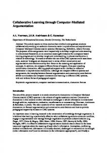
Fig. 1. Image of the Arduino Zero board and its main components TABLE I ATMEL SAMD21G MCU C HARACTERISTICS Parameter
Value
Processor Architecture Instruction Set Clock maximum frequency Operating voltage Flash Memory SRAM Memory Analog-to-digital channels Digital-to-analog channels PWM outputs Real-Time Clock Interfaces
ARM Cortex M0+ 32 bits ARMv6 Thumb-2 48 MHz 3.3 V 256 KB 32 KB 14 (12 bits) 1 (10 bits) 10 (8 bits) Yes USB, I2 S, I2 C, SPI, TWI
II. P LATFORM D ESCRIPTION A. Microcontroller Arduino Zero1 is a microcontroller-based board (see Fig. 1) launched in 2015, that belongs to the Arduino family and, more precisely, to the group of boards with enhance features for more advanced users and complex projects. The main features of the microcontroller SAMD21G that the Arduino Zero board incorporates are summarized in Table I. B. Debugging As a novelty in the Arduino family of boards, the Arduino Zero incorporates an embedded debugging chip: the EDBG from Atmel. As mentioned before, this is one of the most interesting features of this board, providing the possibility to explore the architecture and gain practical experience and understanding of the main concepts related to the course. The EDBG chip allows the remote debugging of the program during execution. Debugging tasks can be done in GNU/Linux systems by connecting to the board by means of OpenOCD2
3990
1 www.arduino.cc/en/Main/ArduinoBoardZero 2 www.openocd.org
TABLE II A RDUINO Z ERO I/O PINS
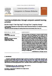
Fig. 2. Memory map of the SAMD21G microcontroller employed in the Arduino Zero board
and using the gdb debugger. Additionally, KDbg3 , a graphical interface for gdb, is used due to its ease of use and the possibility to visualize and execute the assembly code step by step. C. Memory The Arduino Zero board implements a hybrid Harvard architecture in which the program instructions and data are separated into different memory technologies, the internal Flash (256 KB) and SRAM (32 KB) memories, respectively. Both memories, however, are part of the same memory map of the SAMD21G microcontroller, as shown in Fig. 2. D. Input/output The Arduino Zero board has 20 general purpose I/O pins. The operating voltage for these pins is 3.3 V, and a maximum of 7 mA can be sourced or drained from them. The functionalities of these pins are described in Table II and, as shown, some of them can have multiple functionalities depending on the configuration. The precision in terms of bits of the analog inputs and output, and the PWM outputs is provided in Table I. Different I/O transfer techniques can be used, namely interrupts and DMA. Interrupts can be generated from changes in the state of all the digital inputs, except for input 4. The MCU also includes a 12-channel DMA controller. The Arduino IDE incorporates a serial monitor that can be used to print messages as the standard output, and a serial plotter to graphically show the value of a variable. In addition, a built-in LED is connected to pin 13. E. Programming Arduino boards are generally programed using the Arduino IDE. Once the program is compiled it can be loaded using the USB connections available at the programming and native microUSB ports. The Arduino programming language is based
Pin
Functionality
Extra
Interrupts
0 1 2, 7 3, 5, 6 and 8 to 13 4 A0 A1 to A5
Digital I/O Digital I/O Digital I/O Digital I/O Digital I/O Analog input Analog input
Serial RX Serial TX PWM PWM Analog Output -
Yes Yes Yes Yes -
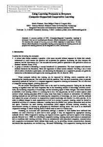
on Wiring, which is derived from C/C++. This language is much more user-friendly than programming in assembly language, and many libraries and examples are available to ease the learning process. An introduction to C programing is given to the students at the beginning of the course. F. Robotics kit To enhance the practical experience of the students, the Arduino Zero platform has been interfaced with a robot kit incorporating several sensors and actuators. This will allow the development of projects and a deeper understanding of the input/output concepts of the course. There are many low-cost robotic kits in the market and we have selected among them the PrintBot Evolution Kit by BQ4 . The Printbot Evolution is a two-wheel mobile robot with a methacrylate chassis that incorporates several sensors integrated in the so-called ZUMbloqs. The plastic parts of the structure are printed with a 3D printer and the designs are open and available for users. The sensors (i.e. inputs) available are: • 2 infrared (IR) sensors for line-follower applications. • 2 light sensors based on LDRs, to detect light sources. • 1 ultrasound sensor, to measure distances to objects. Regarding outputs, the actuators included in the robot are: • 2 continuous rotation servomotors, attached to the wheels to control speed and direction. ◦ • 1 180 servomotor to orientate the ultrasound sensor. • 1 buzzer, to generate sounds. The PrintBot Evolution robot originally incorporates an 8bit Arduino-compatible microcontroller board, the BQ Zum Core. This board has been replaced by the Arduino Zero board. In order to improve the control of the servomotors and provide the required power, a 16-channel 12-bit PWM servo shield from the company Adafruit5 , has been incorporated in the design. Additionally, a sensor shield has also been included to ease the connection of sensors and actuators. The resulting platform is depicted in Fig. 3. III. C OMPUTER S TRUCTURE S YLLABUS The Computer Structure course is taught during the second semester of the first year of the Computer Engineering degree. 4 www.bq.com/es/printbot-evolution
3 www.kdbg.org
5 www.adafruit.com/product/1411
3991
path followed by data during the execution of an instruction. Instructions like CALL, RETURN, PUSH, or POP are particularly interesting because, in order to identify the path that data follow, it is necessary to understand how the call procedure and the stack work. Finally, Section 5 addresses the input/output system from the point of view of the different techniques that can be implemented for the data transfer process, namely: pooling, interrupts and DMA. Students are expected to understand the strengths and weaknesses of each technique and the different context in which their use is appropriate. IV. L AB S ESSIONS AND P ROJECT The course is organized in 4 tutored sessions. Each of these sessions is followed by an evaluation session in which students assess their understanding of the content covered. Finally, during the last 4 sessions students work on a project to apply the previously acquired knowledge.
Fig. 3. Robot platform incorporating the Arduino Zero board and two additional shield boards
The course introduces students to the essential functional units of a computer and how they are interrelated. The course is organized in five separate sections, as follows: • • • • •
Section Section Section Section Section
1. 2. 3. 4. 5.
A. Session 1: Testing the Arduino Zero Harvard architecture
Introduction Memory system Machine Language Datapath Input/Output system
Section 1 is intended to provide students with an overview of the different concepts that will be studied in the following sections and get an overall view of the course. The different elements comprising a computer will be presented in this section from a very general perspective. The introduction also discusses elementary concepts, such as stages in an instruction execution, type of architectures (differences between a Harvard and a von Newman architecture), or the main characteristics of a computer (memory and word size, frequency, transference rate, etc.). Section 2 analyzes the memory system from the point of view of the memory hierarchy (registers on the top of the hierarchy and mass storage at the bottom). Learning the different purposes of the memory hierarchy levels (instructions and operands at the top, long-term data at the bottom) is specifically addressed in this section. Additionally, this section also covers the stack and the role it plays in a call procedure or the separate memories used for storing data and instructions in a Harvard architecture, in contrast with the common memory used for data and instructions in a von Neuman architecture. Section 3 deals with the Instruction Set Architecture (ISA), and the assembly and machine languages. This course does not expect students to learn assembly programming, but they are expected to gain a general understanding of different instruction formats and addressing modes. Additionally, this section also introduces students to the concept of Application Binary Interface (ABI). The ARM ABI is used to explore some aspects such as the call procedure and data alignment. Closely related to section 3, section 4 explores the datapath concepts. Students are expected to understand and identify the
This first session is mainly intended to get students familiar with the hardware and software that they will be using during the course. Following the common practice when starting with a new programming language, students will be illustrated with the Hello, World! application. The result of this exercise consists in printing the message Hello, World! in the standard output. This exercise needs to be adapted to the Arduino Platform in which there is no predefined standard output. For this reason the necessary adjustments will be applied so that a message can be sent to the serial port to be displayed in the serial port monitor provided by the Arduino IDE. After studying the differences between the Harvard and the von Neuman architectures, students are expected to analyze the type of architecture implemented by the Arduino Zero platform. Eventually, they will gain knowledge about the Arduino Zero memory map. Students are prompted to demonstrate that instructions and data are located in different regions of the memory space that physically correspond to different memory technologies, according to Fig. 2. The use of pointers will be introduced here as a mechanism to access memory addresses that correspond to data of interest. To verify that data are stored in the internal SRAM memory students are suggested to declare two variables, one of them automatic and the other static. At this stage, students will be introduced to the fact that different types of variables are located in different memory regions. In any case, both types are expected to be located in a memory address starting with 0x2.... The result of executing the program that follows yields that both variables are stored in memory positions starting with 0x2..., but not in contiguous memory positions. 1 2 3 4 5
s t a t i c c h a r c a d [ ] = ” H e l l o , World ! ” ; void setup ( ) { char t e x t [ 3 2 ] ; S e r i a l . begin (9600) ; i n t a =1;
3992
6
7 8 9 10
s p r i n t f ( t e x t , ” A d d r e s s o f c a d : %x\n A d d r e s s o f a : %x\ n ” ,&a ,& c a d ) ; Serial . print ( text ) ; } void loop ( ) { }
On the other hand, instructions are stored in the internal Flash memory, so this means that all instructions will be located in memory positions starting with 0x0.... To verify this point, students are introduced to a debugging tool. More specifically, they are encouraged to use the gdb debugger with a graphical interface front-end: the KDbg. This tool is very convenient for first year students that face, for first time, the task of code debugging. Despite being traditionally oriented to detect the causes of program malfunctioning, a debugger is an excellent tool for exploring the computer architecture. Moreover, KDbg offers a very intuitive way of exploring the assembler code that corresponds to every single high-level programming statement (see Figure 4). Students are provided with detailed information about the configuration of the Arduino IDE and KDbg to support remote debugging. Please note that up to our current knowledge, the Arduino IDE does not provide support for debugging and for this reason, despite having a board with an embedded debugger, as it is the EDBG, this task has to be externalized to a remote tool. The OpenOCD tool offers a server for our gdb debugger to connect and transfer the control commands. The debugging tasks will therefore be supported on these two tools. Students will use the debugger to explore the memory region in which machine instructions are stored. KDbg offers the possibility of exploring the memory content and format it as strings, yielding the assembler code instructions. Additionally, the binary format can be used allowing students to observe the correspondence between assembler and machine instructions. B. Session 2: Arduino Zero Memory layout This session employs the ABI rules regarding the call procedure and data alignment to analyze how these are implemented by the processor of the Arduino Zero board. Students will be introduced to the use of the processor registers (both general and special purpose registers) and the stack. These two levels of the memory hierarchy have traditionally remained as abstract and intangible elements for first-year students. This sessions is intended to demonstrate the important role that both, registers and the stack, play in the program execution. Once again, KDbg offers us a very useful tool for exploring both registers and the stack. Their content can be easily visualized since general and specific-purpose registers are conveniently labeled and, for the stack, a separate tab is provided. The Cortex M0+ implements a stack that grows downwards (i.e. decrementing memory addresses) from the topmost of the SRAM memory, which is the memory position 0x20007FFF. The first exercise students have to complete is the demonstration of the downwards-growing implementation of stack. The KDbg will be used again to explore how, when calling the loop() function, the stack pointer decrements its value.
Fig. 4. Exploration of the assembler code instructions from the KDbg debugger
The next exercise consists in analyzing how the call procedure is implemented regarding the argument passing and the returned values. General-purpose registers are used for these operations and students are prompted to analyze what the ARM ABI states on this regard and to demonstrate that the Arduino Zero processor implements those rules correctly. KDbg will be used to place breakpoints before and after a function has been called. Students have to analyze the register bank in order to determine whether the rules are satisfied. Finally, the last set of exercises consists in analyzing the ABI alignment rules, specially when applied to data structures. This exercise is intended to demonstrate to the students the importance of writing efficient code, particularly when dealing with scarce-resource devices like the Arduino Board. Several data structures are provided to them, so that they analyze whether such structures are organized in the most efficient way or there is still room for improvement. Finally, students are prompted to write a program that forces a stack overflow and to identify the number of iterations required for the program to crash. This exercise provides students with a clear perspective of how limited is the stack and how important is to make an appropriate use of it. The compiler optimization level is set to 0 in these exercises to force the use of the stack in the call procedure. C. Session 3: Machine Language It is out of the scope of this course to learn how to write a program in assembler code due to the limited time. However, students are expected to have some basic notions about assembler programming. This session will therefore be intended for the students to get familiar with assembler code with assistance of the KDbg tool. Two types of exercises are proposed in this session. The first one consists in analyzing how basic programming tasks are carried out in the ARM assembler language. To do so, students will analyze control flow operations, call procedures and data access. The second type of exercise deals with the use of embedded assembler instructions inside a C-language program. In the first exercise, students are presented with a set of code fragments in C language, along with the corresponding assembler instructions. Questions and modifications on these code fragments in assembler are requested, expecting students to understand the code and therefore gain familiarity with the ARM assembler language. In the second exercise, students are asked to introduce a delay of one clock cycle. This exercise entails the need to figure out the clock frequency and therefore the cycle duration
3993
and to understand how the delay() function works. This should lead students to the conclusion that the smallest delay they can produce is of 2 µs using that function. On the contrary, given that the processor works at 16 MHz, one cycle needs 62,5 ns to be executed. By embedding assembler code into the Arduino program students can achieve a 1 cycle delay in their code. To do so, they are introduced to the use of the asm("nop") function. The nop assembler instruction does not perform any operation but takes one cycle to be executed. D. Session 4: Input/Output In this session the students are given a set of basic and functional examples to work with all the sensors and actuators included in the robot. In addition, an example on how to manage interrupts is provided. In order to use the servos connected to the Adafruit PWM shield, students have to learn how to include new specific libraries in the Arduino IDE. E. Project: Line-follower robot To complete the practical experience of the students, a project to be completed in teams is proposed. The project is to develop a practical application with the robot. In this first year, a line-follower robot has to be programed. A very basic and functional version of a line-follower is provided to the students as a starting point, as shown below. 1 2 3
4 5 6 7 8 9 10 11 12 13 14 15 16 17 18 19 20 21 22 23 24 25 26 27 28 29 30 31
# i n c l u d e # i n c l u d e
A d a f r u i t P W M S e r v o D r i v e r pwm = Adafruit PWMServoDriver ( ) ; / / Pulse lengths : # d e f i n e SERVO CCW 280 / / C o u n t e r c l o c k w i s e r o t a t i o n # d e f i n e SERVO STOP 340 / / S e r v o s t o p p e d # d e f i n e SERVO CW 400 / / C l o c k w i s e r o t a t i o n i n t Right servo =0; / / r i g h t servo channel i n t L e f t s e r v o =1; / / l e f t servo channel i n t BLACK= 0 ; / / B l a c k l i n e d e t e c t e d void setup ( ) { pwm . b e g i n ( ) ; pwm . setPWMFreq ( 6 0 ) ; / /PWM f r e q u e n c y ( 6 0 Hz ) pinMode ( 2 , INPUT ) ; / / R i g h t IR s e n s o r p i n pinMode ( 3 , INPUT ) ; / / L e f t IR s e n s o r p i n } void loop ( ) { i n t Right IR= d i g i t a l R e a d ( 2 ) ; i n t Left IR= digitalRead (3) ; i f ( R i g h t I R ==BLACK) { pwm . setPWM ( L e f t s e r v o , 0 ,SERVO CCW) ; }else { pwm . setPWM ( R i g h t s e r v o , 0 , SERVO STOP ) ; } i f ( L e f t I R ==BLACK) { pwm . setPWM ( R i g h t s e r v o , 0 ,SERVO CW) ; }else { pwm . setPWM ( R i g h t s e r v o , 0 , SERVO STOP ) ; } delay (10) ; }
they come across when increasing the number of tasks to be completed in the loop() function and how it affects the linefollower performance. V. C ONCLUSIONS The use of the Arduino Zero board and a robot kit in the labs of the Computer Structure course is proposed in this paper. A better matching between the concepts presented in the theory sessions and the labs is expected, in comparison to previous experiences in the same course using different platforms. The inclusion of an embedded debugger in the Arduino Zero board, and the use of a gdb front-end such as KDbg provides a very powerful tool to easily explore the memory or analyze the assembler instructions that correspond to the high-level code. Future lines of work will consist in the assessment of this educational experience by comparing the performance and motivation of an experimental group doing the labs with Arduino Zero and a control group doing the previous labs using the Nintendo DS console. Moreover, the use of this Arduino-based lab platform will be extended to other courses of the Computer Science degree. ACKNOWLEDGMENT This work has been partially funded by the Spanish Ministry of Economy and Competitiveness under project REBECCA (TEC201458036-C4-1-R), by the Regional Government of Castilla-La Mancha under project SAND (PEII 2014 046 P) and by the University of Castilla-La Mancha R&D Plan under the access contracts to the Spanish system of science, technology and innovation call, which is partially funded by the European Social Fund (31/07/2014 Resolution, published in the DOCM on the 25 of August 2014).
R EFERENCES
The teams are asked to improve the program so that the robot can complete a given circuit and minimize the time required to complete one lap. They are also asked to integrate the other sensors and actuators available and to be creative to find new functionalities and features. One of the important lessons learned while developing the project are the issues
[1] S. Papavlasopoulou, M. N. Giannakos, and L. Jaccheri, “Empirical studies on the Maker Movement, a promising approach to learning: A literature review,” Entertainment Computing, vol. 18, pp. 57–78, 2017. [Online]. Available: http://dx.doi.org/10.1016/j.entcom.2016.09.002 [2] G. Chen, J. Shen, L. Barth-Cohen, S. Jiang, X. Huang, and M. Eltoukhy, “Assessing elementary students’ computational thinking in everyday reasoning and robotics programming,” Computers and Education, vol. 109, pp. 162–175, 2017. [Online]. Available: http: //dx.doi.org/10.1016/j.compedu.2017.03.001 [3] M. U. Bers, L. Flannery, E. R. Kazakoff, and A. Sullivan, “Computational thinking and tinkering: Exploration of an early childhood robotics curriculum,” Computers and Education, vol. 72, pp. 145–157, 2014. [Online]. Available: http://dx.doi.org/10.1016/j.compedu.2013.10.020 [4] F. B. V. Benitti, “Exploring the educational potential of robotics in schools: A systematic review,” Computers and Education, vol. 58, no. 3, pp. 978–988, 2012. [Online]. Available: http://dx.doi.org/10.1016/ j.compedu.2011.10.006 [5] N. Spolaˆor and F. B. Benitti, “Robotics applications grounded in learning theories on tertiary education: A systematic review,” Computers & Education, vol. 112, pp. 97–107, 2017. [Online]. Available: http://linkinghub.elsevier.com/retrieve/pii/S0360131517300970 [6] C. A. Canizares and Z. Faur, “Advantages and disadvantages of using various computer tools in electrical engineering courses,” IEEE Transactions on Education, vol. 40, no. 3, pp. 166–171, 1997. [7] M. J. Santofimia and F. Moya, “Nintendo DS: A pedagogical approach to teach computer architecture,” in Proceedings of the 2009 International Conference on Embedded Systems & Applications, ESA 2009, July 13-16, 2009, Las Vegas Nevada, USA, H. R. Arabnia and A. M. G. Solo, Eds. CSREA Press, 2009, pp. 269–273. [8] E. Larraza-Mendiluze, N. Garay-Vitoria, J. I. Mart´ın, J. Muguerza, T. Ruiz-V´azquez, I. Soraluze, J. F. Lukas, and K. Santiago, “GameConsole-Based Projects for Learning the Computer Input / Output Subsystem,” vol. 56, no. 4, pp. 453–458, 2013.
3994
Powered by TCPDF (www.tcpdf.org)