Learning Patch Correspondences for Improved Viewpoint Invariant Face Recognition Ahmed Bilal Ashraf
Simon Lucey Carnegie Mellon University
Tsuhan Chen
[email protected] ,
[email protected] ,
[email protected]
Abstract Variation due to viewpoint is one of the key challenges that stand in the way of a complete solution to the face recognition problem. It is easy to note that local regions of the face change differently in appearance as the viewpoint varies. Recently, patch-based approaches, such as those of Kanade and Yamada, have taken advantage of this effect resulting in improved viewpoint invariant face recognition. In this paper we propose a data-driven extension to their approach, in which we not only model how a face patch varies in appearance, but also how it deforms spatially as the viewpoint varies. We propose a novel alignment strategy which we refer to as “stack flow” that discovers viewpoint induced spatial deformities undergone by a face at the patch level. One can then view the spatial deformation of a patch as the correspondence of that patch between two viewpoints. We present improved identification and verification results to demonstrate the utility of our technique.
Assume Patch Correspondences ( as in [4] )
Probe Image
p(sr | ω = I)
p(sr | ω )
p(sr | ω = C)
Gallery Image
sr (a)
Learn Patch Correspondences
p(sr | ω = I)
p(sr | ω )
Probe Image
p(sr | ω = C)
Gallery Image “Rectify”
sr
(b)
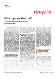
Figure 1. Illustration of how learning patch correspondences leads to viewpoint invariance. In the above figure, sr represents a similarity score between the r-th gallery and probe patch e.g. sum of square differences (SSD). p(sr |ω) is the distribution of the rth SSD given that the gallery and probe have the same identity (ω = C : client) or they have different identity (ω = I : impostor). (a) If we assume a correspondence between gallery and probe patches [4], client and impostor distributions are overlapping. (b) If we learn patch correspondences (proposed in this paper), the distributions become separated leading to better recognition.
1. Introduction Face recognition is a task that humans perform with great facility. In spite of some early successes in automatic face recognition and significant research in the area, this problem is far from being solved. In fact, variations in parameters like viewpoint and illumination have been shown [10] to be the major obstacles. In particular, recognizing a face given a single image per subject is one of the key challenges for the face recognition community. Since a human head has non-planar geometry, portions of the face containing significant 3D depth variation undergo noticeable appearance changes as the viewpoint varies (e.g. the nose). A way to handle this disparity of variation amongst parts of the face is to model it as a collection of subregions/patches. An initial direction along this line was proposed in the seminal work of Kanade and Yamada [4]. In [4] the authors present a systematic analysis of the discriminative power of different regions of the face as
a function of viewpoint. For every subregion they derive a utility score based on pixel differences leading to a probabilistic framework for recognition. A drawback to this approach, however, is that it assumes perfect correspondence between the gallery and probe patches. As pointed out in [8] this assumption can lead to poor performance in the presence of large viewpoint mismatch. To circumvent this limitation, Lucey and Chen [8] recently described an approach for modeling the joint distri1
bution of gallery and probe appearances. They extend the work of [4] by modeling the joint appearance of individual patches of the gallery image and the whole probe image. A major benefit of this approach is that it does not assume any alignment between the gallery and probe images, leading to improved performance over Kanade and Yamada’s method. This approach, however, does have some shortcomings. Specifically, the approach models redundant information by learning a distribution for every possible patch-whole pair. This is undesirable from two perspectives. First, this makes the training of the joint distribution models very slow. Second, at run time it is computationally expensive to estimate a likelihood score for each patchwhole combination. To avoid these problems, ideally we would like to model the distribution of the corresponding gallery and probe patches only. Hitherto, it has been unclear how such correspondences can be learnt. In this paper, we propose to learn patch-level correspondences through the estimation of the affine warp displacement between each gallery and probe patch (see Figure 1). A motivation for employing an affine warp lies in its natural ability to model planar surfaces undergoing viewpoint change [3]. To fulfill the above goal, we have made the following novel contributions in this paper: • We propose a data-driven framework to learn correspondences between patches coming from two different viewpoints of a face. We refer to this approach as “stack-flow”. Additionally, we demonstrate that our proposed approach is far more effective for learning patch-correspondences than traditional optical-flow methods. (Section 2.3) • We extend Kanade and Yamada’s work [4] to learn the discriminative power of the warped patches estimated through stack-flow. (Section 3.2) • Finally, we demonstrate the utility of our proposed techniques by showing improved identification and verification performance on the FERET face dataset. (Section 3)
1.1. Related Work A number of previous studies have presented approaches that attempt to recognize a non-frontal probe image, given a single gallery image (usually frontal). In what is commonly considered one of the key seminal works in the area, Blanz and Vetter [2] employed an approach that was able to fit a pre-learned 3D model to an input face and perform recognition using the implied 3D representation of the face. This approach, although giving good results, has a number of drawbacks: (i) the requirement for a large amount of offline depth information, (ii) a need for dense registration, (iii) a costly model fitting step. A related approach was proposed
W(x,p)
Ir
Probe Image, I
Tr
Gallery Image, T
Figure 2. Image-to-image alignment. The goal is to find warp parameters pr that achieve a correspondence between the probe patch Ir and the gallery patch Tr .
by Liu and Chen [5] in which the authors approximated the human head with a 3D ellipsoid. This method, like [2], suffers from the computational expense involved in online fitting of the model to a test image. Another direction is to look for features that are invariant to viewpoint, as proposed by Prince and Elder [7]. Although promising, this technique requires manual labeling of a significant number of feature points, and also involves online model fitting like [2] and [5]. Moreover, the above discussed approaches are generative in the sense that they rely on fitting their respective models to a test image based on minimizing reconstruction error. Their expressability is thus constrained by the prelearned model.
2. Learning Patch Correspondences In this section we shall investigate how patch-level correspondences can be learnt between gallery and probe images. The key idea is to allow the patches to deform spatially (see Figure 1(b)) under the influence of a parametric affine warp. Let the warp function be parameterized by the vector p = [p1 , p2 , ...., pm ]T , where m = 6 for an affine warp. We can express the warp function as x! = W (x, p), where x and x! represent the input and warped coordinates respectively. Using this framework, the patch correspondence problem can now be formulated as the problem of finding the N warp displacements between the N gallery and probe face patches, T
Φ = [p1 p2 · · · pN ]
(1)
Let us begin by exploring how we can learn the above warp displacements Φ.
2.1. Image-to-Image Alignment An obvious method to learn Φ is to employ conventional methods in computer vision for image-to-image alignment. The Lucas-Kanade algorithm [6] is one of the most effective techniques for image alignment. In this section we explain
WSTK Φ STK
WSTK Φ STK
W(x,p)
Ir
Tr
Φonline Probe Image, I
ΦSTK
Gallery Image, T
Avg. Profile Face (a)
Frontal
Profile
ΦAVG Avg. Frontal Face
(b)
Figure 3. Methods based on image-to-image alignment. (a) Online flow : Learns N patch warps between the probe and gallery images in an online fashion. (b) Offline average flow: Learns N patch warps Φavg between average profile and frontal faces.
Stack
Stack
(Stack-I)
(Stack-II)
Figure 4. Illustration of stack-flow. Learning N patch warps Φstk (consistent across the entire stack) that align the patches of the two stacks as a whole.
Equation 3 is given by: how the Lucas-Kanade algorithm can be used to find warps that achieve patch-by-patch alignment between two images. Consider two images captured at two different viewpoints as shown in Figure 2. We divide the images into subregions/patches, and then seek to find a warp that aligns the r-th region in the two images. Let I and T represent the probe and gallery images respectively. Also, let the subscript r be an index to the r-th patch in each image. Our main goal now is to find the warp parameters that would make the r-th patch in both images as similar as possible. In other words we seek a p that minimizes the following error term: ! (Ir (W (x, p)) − Tr (x))2 (2) Er =
!
∂W T ) (Tr (x) − Ir (W (x, p))) ∂p x (5) where H(img) is the pseudo Hessian matrix for image-toimage alignment given by, ∆p = H−1 (img)
(∇Ir
H(img) =
! x
(∇Ir
∂W T ∂W ) (∇Ir ) ∂p ∂p
(6)
We can now update the warp parameters (p ← p + ∆p) and iterate till the parameters p converge. This procedure is applied independently for every patch.
x
Minimizing Er is a non-linear optimization task. The Lucas-Kanade algorithm is able to find an effective solution to Equation 2 by iteratively linearizing Er and refining the initial guess p. This linear approximation can be seen in, Er ≈
! x
(Ir (W (x, p)) + ∇Ir
∂W ∆p − Tr (x))2 ∂p
(3)
where we are now attempting to estimate ∆p (rather than p). The parameter p is then updated ( p ← p + ∆p ) until convergence. ∂Ir r In Equation 3, ∇Ir = ( ∂I ∂x , ∂y ) is the gradient of Ir ∂W computed at W (x, p), and ∂p is the Jacobian of the warp given by: ∂Wx ∂Wx x · · · ∂W ∂p1 ∂p2 ∂pm ∂W = (4) ∂p ∂Wy ∂Wy ∂Wy · · · ∂pm ∂p1 ∂p2 The explicit solution for the ∆p that minimizes Er in
2.2. Employing Image-to-Image Alignment To learn patch correspondences using image-to-image alignment we employed two methods as shown in Figure 3. In the first strategy (Figure 3(a)), we attempt to learn N patch warps between an input probe image and the proposed gallery image. A match score can then be computed based on the degree of correspondence achieved by the learned warps. Since no training is required and warps are learnt in an online fashion, this strategy can be termed as “online flow”. In the second method, which we refer to as “offline average flow” (Figure 3(b)), we first compute an average face image for the frontal and profile viewpoints respectively from an ensemble of offline face images. We then learn N patch warps between the two average faces. Learning offline warps has the advantage of relieving the online stage of the burden of warp fitting. The employment of multiple examples is advantageous as it allows us to “average” across noisy artifacts that may be present in a single face example.
2.3. Stack-to-Stack Alignment A disadvantage, however, of taking the average in the “offline average flow” method is that we may lose person specific texture variation in the averaging process. To fully span the extent of variation contained in the offline data, we propose to learn a warp that aligns two stacks of images as a whole. For this we learn a warp that is consistent across the entire stack and aligns a patch in the stack of profile faces to a patch in the stack of frontal faces. We call this technique “stack-flow”. The idea is illustrated in Figure 4. In Figure 4, Stack-I consists of images of subjects in the profile viewpoint. Stack-II contains images of the same subjects but in a frontal viewpoint. The goal of stack-flow is to find a warp which, when applied to the r-th patch of Stack-I images, achieves the best alignment for the r-th patch across the two stacks. We can express the above stated goal as the minimization of the following error: !! (Ij,r (W (x, p)) − Tj,r (x))2 (7) Er(stk) = x
j
where Ij,r and Tj,r represent the r-th patch in the j-th image of Stack-I and Stack-II respectively. The error in Equation 7 can also be minimized in an iterative fashion starting with an initial estimate of parameters p. Following a similar procedure as in Section 2.1 we can find the following solution for stack-flow, !! AT ∆p(stk) = H−1 j,r (Tj,r (x) − Ij,r (W (x, p))) (stk) x
j
(8) where Aj,r = (∇Ij,r ∂W ), and the pseudo Hessian matrix ∂p for stack-flow is given by: H(stk) =
!! j
x
(∇Ij,r
∂W T ∂W ) (∇Ij,r ) ∂p ∂p
(9)
The warp parameters for every patch are found independently through iteratively applying Equation 8 until convergence where, )T ( (10) Φstk = p1(stk) p2(stk) · · · pN (stk)
are the final warps for each patch. If we compare Equations 6 and 9 for H(img) and H(stk) respectively, we can see that the Hessian matrix for the stack-flow method incorporates steepest descent images for the entire stack unlike the Hessian matrix for image-toimage alignment which includes only one steepest descent image. Moreover, the image-to-image alignment solution (Equation 5), when used to align average images, will fail to accommodate texture variation, whereas the stack-flow solution (Equation 8) will handle it. This problem is illustrated in Figure 5. In Figure 5 we face the problem of
Stack-I
Stack-II
Avg. Stack-I Image
Avg. Stack-II Image
Figure 5. Illustration of how the average warp fails to handle texture variation. In this extreme example, the images in Stack I are clearly a displaced version of the images in Stack II. However, by taking the average of these two stacks this difference is no longer clear. Our proposed “stack-flow” technique can obtain the correct alignment for this extreme case.
aligning images in Stack-I to images in Stack-II. Clearly, the images in Stack-I are displaced versions of the images in Stack II. The average images for both the stacks are exactly the same, so that any image-to-image algorithm would deem them to be in perfect alignment. The stack-flow technique, however, is able to handle this extreme situation as it attempts to align the two stacks rather than two images. The stack-flow procedure thus has the following desirable attributes: • It achieves immunity to noise by using the stack of images as a constraint and thus avoids the averaging process. • By virtue of avoiding averaging, it is also better at handling texture variation which an average warp fails to do.
3. Experiments We conducted our experiments on the FERET database. FERET consists of images from approximately 200 subjects. We randomly divided the database into two groups based on subjects (Group-I and Group-II). For each subject, images have been captured at viewpoints bi, bh, bg, bf, ba, be, bd, bc, bb which roughly correspond to viewpoint angles of −60◦ , −40◦ , The faces were −25◦ , −15◦ , 0◦ , 15◦ , 25◦ , 40◦ , 60◦ . first coarsely registered so that the eye coordinates align, the line joining the eyes is horizontal and the distance between the eyes is nominal. The face area was cropped to
90
80
80
Identification Rate (%)
100
90 Identification Rate (%)
100
70 60 50 40 30 Stack Flow Avg. Flow Online Flow Raw SSD
20 10
(a)
(b)
(c)
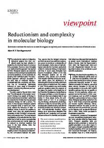
Figure 6. Example of warp learning using stack-flow. (a) A nonfrontal face with the learned warps superimposed. Tracking along the nose is especially interesting, as the learned warps find good patch correspondence in spite of 3D depth variation around the nose (b) A frontal viewpoint of the same subject. (c) A “rectified” version of (a) by applying the learned warps on the non-frontal face.
give a 100x130 image. The face was then divided into 27 non-overlapping patches each of size 16x16. To learn patch correspondences, we parameterized the warp (between patches at two viewpoints) as an affine warp. To start the iterative process of warp learning (Sections 2.1, 2.3), warp parameters were initialized to a zero vector for all the patches. Example output of warp learning using stack-flow is shown in Figure 6. It is encouraging to observe how our algorithm learns warps for areas with significant 3D depth variation (e.g. the nose), and achieves good patch-level correspondences. It is also interesting to note how patches on the near side of the face have grown in size, while the patches on the far side have reduced in size.
0 −60
−40
−20
0
60 50 40 30 Stack Flow Avg. Flow Online Flow Raw SSD
20 10 40
60
0 −60
Probe Pose (degrees)
−40
−20
0
20
40
60
Probe Pose (degrees) (b)
(a)
Figure 7. Comparison of warp strategies. (a) Warps learnt on Group-I and tested on Group-II. (b) Warps learnt on Group-II and tested on Group-I. In both the plots stack-flow is better than the other warping strategies.
faces as discussed in Section 2.3 (Figure 5). The stack-flow addresses these concerns and hence outperforms the other warping strategies.
3.2. Probabilistic Stack-Flow It is easy to note that local areas of the face change differently as the viewpoint varies. Recently Kanade and Yamada [4] have made use of this effect resulting in improved viewpoint invariant performance. Taking direction from [4], we investigate the discriminative power of each warped patch as a function of viewpoint. We call this technique “probabilistic stack-flow”. We use the sum of squared differences (SSD) as a similarity value between a gallery patch and a warped probe patch. The aim is to derive the probability distributions for patch SSD’s given the probe viewpoint i.e.:
3.1. Evaluating Warp Strategies To evaluate the warping strategies described in Section 2, we ran recognition experiments using a nearest neighbor classifier based on the sum of squared differences (SSD) between the warped probe and gallery patches. We first learnt warps using images from Group-I and conducted recognition experiments on Group-II. To cross-validate, warps were learnt on Group-II and experiments conducted on Group-I. The results are shown in Figure 7. A similar trend was observed in the cross-validated results. For both the plots in Figure 7, stack-flow gives better performance than the other warping strategies. A few observations stemming from Figure 7 are as follows. The online flow has the lowest performance, and is hardly different from raw-SSD’s (SSD’s computed without warping). The main reason behind the low performance of online flow is its susceptibility to noise. Since this technique attempts to find warps between a pair of images at a time, it has more tendency to respond to noise. The average flow performs better than the online approach because it filters out the noise in the averaging process. However, in the process, it becomes deficient in handling variation among
20
70
p(sr |φp , ω) , ω ∈ {C, I}
(11)
where sr is the SSD score for the r-th patch, and φp is the probe viewpoint. The variable ω refers to classes when gallery and probe images belong to the same subject (client : C) or different subjects (impostor: I). We compute the SSD histograms for warped training images to learn these distributions. Once the histograms are computed, we approximate the distribution in 11 with a log-normal distribution as follows: * ,2 + 1 1 log(sr ) − νr ω √ exp − p(sr |φp , ω) = 2 γr ω γr ω 2πsr (12) where the parameters νr ω and γr ω are the log-means and log-standard-deviations respectively for the class ω, and ω ∈ {C, I}. These parameters can be estimated from the SSD histograms as follows: νr ω (γr ω )2
= E{log(sr )|ω} = E{(log(sr ))2 |ω} − (νr ω )2
(13)
Lucey and Chen have argued in [8] that it is advantageous to use a log-normal, rather than normal, distribution for mod-
90
80
80
Identification Rate (%)
100
90 Identification Rate (%)
100
70 60 50 40 30 20 10 0 −60
−40
−20 0 20 Probe Pose (degrees) (a)
60 50
100
90
90
80
80
Identification Rate (%)
Identification Rate (%)
100
60 50 40 30 20
−40
−20 0 20 40 Probe Pose (degrees) (b)
60
10 0 −60
−40
−20
0
20
Probe Pose (degrees) (a)
60 50 40 30 Prob. Stack Flow Kanade et al [4] Eigen−Faces
10 40
60
ΦC
ΦA
ΦB
ΦC
0 −60
40° Stack
25°
15°
Frontal
Stack
Stack
Stack
ΦA
ΦB
ΦC
40° to 25°
25° to 15°
15° to 0°
Φcomposite
Figure 10. Illustration of composite warp learning. Warps are learned between nearby viewpoints e.g. 40◦ −25◦ , then 25◦ −15◦ , and then 15◦ −0◦ . These warps can be composed to give one composite warp −Φcomposite .
70
20
Prob. Stack Flow Kanade et al [4] Eigen−Faces
ΦB
Prob. Stack Flow Stack Flow
Figure 8. Comparison of probabilistic stack-flow with stack-flow. (a) Warps learnt on Group-I and tested on Group-II. (b) Warps learnt on Group-II and tested on Group-I. In both plots probabilistic stack-flow performs better than stack-flow
70
ΦA
30
0 −60
60
ΦC
40
10 40
ΦB
70
20
Prob. Stack Flow Stack Flow
ΦA
−40
−20 0 20 Probe Pose (degrees) (b)
40
60
Figure 9. Comparison of probabilistic stack-flow with Kanade & Yamada’s approach [4]. (a) Warps learnt on Group-I and tested on Group-II. (b) Warps learnt on Group-II and tested on Group-I. Both the plots show similar trend. Probabilistic stack-flow outperforms the probabilistic framework of [4]. The difference in performance is more accentuated for larger viewpoint variations.
eling patch SSD values. A possible reason for this, as put forth in [8], is the increased likelihood of client and impostor distributions to be skewed towards a zero SSD value when there is less viewpoint mismatch. By using the interviewpoint patch correspondences (Section 2.3) to rectify a probe image, we reduce the expected viewpoint mismatch. It is thus expected that the warps learnt through the stackflow procedure would further the capacity of the log-normal distribution to model SSD values for warped probe patches. We can now obtain the log-likelihood ratio L that the ensemble of probe and gallery patches belong to the same subject, ! log p(sr |ω = C, φp ) − log p(sr |ω = I, φp ) (14) L= r
assuming the prior probabilities P (ω) for ω ∈ {C, I} are equal. For the identification task we obtain an L for each gallery image and the claimant probe image. A correct decision is obtained if the maximum L across all the gallery images corresponds to the same identity as the claimant probe image. Identification results are typically returned as a per-
centage with 100% being the best performance and 0% being the worst. A comparison between stack-flow and probabilistic stack-flow is given in Figure 8 for the task of identification. The identification rate curve for probabilistic stackflow remains above that of stack-flow for all the viewpoints. We now compare the probabilistic stack-flow method with Kanade and Yamada’s probabilistic framework [4] and the conventional Eigen-Faces based approach (Figure 9). For all the viewpoints, our method outperforms the technique proposed in [4]. The difference in performance is more pronounced as the probe viewpoint angle increases. We observed a similar trend when the training and testing sets were swapped for cross-validation, as shown in Figure 9.
3.3. Composite Warp Learning With increasing viewpoint disparity between the probe and gallery images, it becomes harder to learn a warp from a profile face directly to the frontal face. To handle this problem we propose to learn incremental warps between near-by viewpoints e.g. between −60◦ and −40◦ etc. To get to the frontal view, warps between intermediate viewpoints can then be combined to give what we term as the “composite warp”. This approach is illustrated in Figure 10. A comparison between composite warp and direct warp is given in Figure 11. For lesser viewpoint variations, both the techniques performed equally well. However, at extreme probe viewpoints, composite warp has better performance. We now move on to assess our technique for the task of face verification.
Identification Rate (%)
100
A detailed comparison in terms of ROC curves for different viewpoints is given in Figure 13. The steeper the ROC, the more desirable it is, as it indicates a high hit rate for a low FAR. For all the viewpoints, ROC of our approach is steeper than that of [4].
Direct Composite
80 60 40 20 0
4. Conclusions and Discussion -60°
-40° 40° Probe Pose
60°
Figure 11. Comparison between composite and direct warps at extreme viewpoints. Both approaches employ probabilistic stackflow to learn warps. Composite warp gives better performance for extreme probe viewpoints. 100
100 Eigen−Faces Kanade & Yamada Prob. Stack Flow
80 70 60 50 40 30 20
80 70 60 50 40 30 20
10 0 −60
Eigen−Faces Kanade & Yamada Prob. Stack Flow
90 Equal Error Rate (%)
Equal Error Rate (%)
90
10 −40
−20
0
20
40
60
0 −60
Probe Pose (degrees) (a)
−40
−20 0 20 Probe Pose (degrees)
40
60
(b)
Figure 12. Verification results. Comparison in terms of equal error rate (EER) between probabilistic stack-flow and Kanade and Yamada’s probabilistic framework [4]. (a) Warps learnt on Group-I and tested on Group-II. (b) Warps learnt on Group-II and tested on Group-I. Both plots show a trend in which probabilistic stack-flow has the lowest EER for all the viewpoints.
3.4. Verification Experiments In verification we have to accept or reject a claimant’s claim of being a particular subject. Typically, the claimant’s match score is compared to a threshold. The claim is accepted if the match score is greater than or equal to the threshold, and rejected otherwise. There are two metrics associated with a verification system: (i) False Rejection Rate (FRR) that represents the rejection of a true client, (ii) False Acceptance Rate (FAR), that represents acceptance of an impostor. These two rates vary according to the choice of the threshold and the overall performance is usually represented in terms of Receiver Operating Characteristics (ROC), which is a plot of FAR vs. Hit Rate. The hit rate is the rate of acceptance of true clients. Often, a single measure, Equal Error Rate (EER) is used to gauge a verification system. The EER is determined by finding the threshold at which the two errors (FAR and FRR) are equal. Using the log-likelihood ratio derived in Equation 14, we can adapt our technique for the task of verification. We compare our method probabilistic stack-flow with [4] in terms of EER in Figure 12. EER for our technique remains lower than that of [4] for all the viewpoints.
In this paper we have presented a novel strategy which we refer to as “stack-flow” for aligning a stack of images at the patch-level. This approach is able to learn correspondences between gallery and probe viewpoints in a superior manner as compared to conventional image-to-image alignment techniques. Based on this learnt correspondence we have proposed an extension to Kanade and Yamada’s viewpoint invariant face recognition work [4], which we refer to as probabilistic stack-flow, to model the discriminative power of corresponding gallery and probe patches. We have shown that our technique outperforms Kanade and Yamada’s original method in both recognition and verification tasks. We have also demonstrated the benefit of composing incremental warps (composite warp) to handle large viewpoint variations. A limitation of our approach lies in its inability to handle situations where patches become occluded at extreme viewpoints. For example, our current method will fail if we need to match a left profile face with a right profile face. Future work shall try and remedy this situation through the employment of “missing data” techniques. In the future we also aim to integrate our work with a face detection frontend such as [9].
References [1] S. Baker and I. Matthews. Lucas-kanade 20 years on: A unifying framework. International Journal of Computer Vision, 56(3):221 – 255, March 2004. [2] V. Blanz and T. Vetter. Face recognition based on fitting a 3d morphable model. IEEE Transactions on Pattern Analysis and Machine Intelligence, 25(9), 2003. [3] D. A. Forsyth and J. Ponce. Computer Vision: A Modern Approach. Prentice Hall, 2003. [4] T. Kanade and A. Yamada. Multi-subregion based probabilistic approach toward pose-invariant face recognition. Proceedings of IEEE International Symposium on Computational Intelligence in Robotics Automation, 2:954–959, 2003. [5] X. Liu and T. Chen. Pose-robust recognition using geometry assisted probabilistic modeling. IEEE Computer Society Conference on Computer Vision and Pattern Recognition (CVPR), 2005. [6] B. Lucas and T. Kanade. An iterative image registration technique with an application to stereo vision. Proceedings of Imaging understanding workshop, pages 121–120. [7] S. Prince and J. Elder. Tied factor analysis for face recognition across large pose changes. British Machine Vision Conference (BMVC), 2006.
100
100
80
80
80
80
60
60
60
60
40
40
40
40
20
20
20
20
0
0 20 40 60 80 100
0
0 20 40 60 80 100
0
FAR (%) Probe Pose = −25°
FAR (%) Probe Pose = −15°
0 20 40 60 80 100
0
FAR (%) Probe Pose = −40°
Hit Rate (%)
100
Hit Rate (%)
100
0 20 40 60 80 100 FAR (%) Probe Pose = −60°
100
100
100
80
80
80
80
60
60
60
60
40
40
40
40
20
20
20
20
Hit Rate (%)
100
0
0 20 40 60 80 100 FAR (%) Probe Pose = 15°
0
0 20 40 60 80 100 FAR (%) Probe Pose = 25°
0
0 20 40 60 80 100 FAR (%) Probe Pose = 40°
0
Hit Rate (%)
Probabilistic Stack Flow Kanade & Yamada, [4]
0 20 40 60 80 100 FAR (%) Probe Pose = 60°
Figure 13. ROC curves for verification at different viewpoints. A comparison is shown between the ROC curves of our method probabilistic stack-flow and Kanade and Yamada’s approach [4]. For almost all the viewpoints, ROC of our technique is steeper than that of [4]. The difference is more prominent for larger viewpoint variations. [8] S.Lucey and T. Chen. Learning patch dependencies for improved pose mismatched face verification. IEEE Computer Society Conference on Computer Vision and Pattern Recognition, June 2006. [9] P. Viola and M. J. Jones. Robust real-time face detection. International Journal of Computer Vision, 57(2):137–154, 2004. [10] W. Zhao, R. Chellapa, A. Rosenfield, and P. J. Phillips. Face recognition: A literature survey. Technical report, University of Maryland, 2000.