Learning precise 3D reaching in a humanoid robot Lorenzo Natale, Francesco Nori, Giulio Sandini
Giorgio Metta
Italian Institute of Technology Via Morego 30, Genova, ITALY {lorenzo.natale, francesco.nori, giulio.sandini}@iit.it
University of Genoa and Italian Institute of Technology Via Morego 30, Genova, ITALY
[email protected]
Abstract— In this paper we discuss the implementation of a precise reaching controller on an upper-torso humanoid robot. The proposed solution is based on a learning strategy which does not rely on a priori models of the kinematics of the arm nor of that of the head. After learning, the robot can reach for visually identified objects in 3-D space by integrating an open loop and a closed loop component; the open loop controller allows ballistic movements, while the closed loop one performs precise positioning of the hand in visual space. Differently from other approaches we handle the critical case of redundancy in the head and the arm and propose a solution that although preliminary possesses some biological relevance. Index Terms— Visual servoing, reaching, learning, development, humanoid robotics.
I. I NTRODUCTION Growing evidence in developmental psychology shows the importance of motor activity for cognitive development in humans [1]. In particular it is through manipulation that infants gain direct access to objects and discover properties that otherwise would remain hidden. This concerns for example properties like weight, shape, texture and softness that are, if not impossible, at least extremely hard to perceive by using visual information alone. In adults information originating from motor activity and direct contact with the environment, supports perception [2]; during development the physical interaction with the environment provides infants with natural invariances that are useful occasions for learning. Interestingly, motor and perceptual development seem to follow synchronous schedules as if new achievements in the motor system were promoting the development of new perceptual skills [3]. Research in developmental robotics has demonstrated the importance of motor activity (in particular manipulation) for visual and haptic perception [4]. One of the limitations of these approaches is that controlling the interaction between the robot and the environment is difficult especially when precise models are not available. Experiments with robots have thus focused on situations in which the interaction with objects is relatively simple. For these reasons the investigation of perceptual development in robots requires addressing the problem of motor development first. In this context we focus on reaching, which is a clear prerequisite for manipulation. Reaching can be solved either by visual servoing [5] or by a model-based open loop [6],
[7] approach. Visual servoing requires the simultaneous view of the hand and of the target and it is limited by the rate of measurement of these two quantities from images. Visual servoing en force of the feedback loop is robust to noise and errors guaranteeing convergence to the target even in the presence of rough estimates of the controller parameters (typically a visuo-arm Jacobian). On the contrary, an open loop controller can be as fast as the motors can be at the price of precision which is bound to the modeling inaccuracies or sensor noise. Results in developmental psychology suggest that both solutions might be adopted by the brain. Clifton et al. [8] tested whether infants require vision of their hand when reaching; they found that infants’ ability to touch (and grasp) objects is independent of whether sight of the hand is available or not. Another set of experiments [9] show that later on in development there is an increase of visual guidance in reaching. Together these results suggest the hypothesis that there are two “distinct” reaching mechanism: one that relies on “proprioceptive” information alone and one that uses “visual feedback” to compensate for errors in the visual domain. There are studies that show the link of the control of the gaze in relation to the precision of reaching [10]. In this paper we integrate the two modes of control with an approach based on the hypothesis that the target object is fixated. We use the open loop controller to bring the hand close to the target. The closed loop controller is activated when visual feedback from the hand is available. In practice, we show that the error could be made arbitrarily small. The problem of redundancy is solved in the first case by imposing additional constraints on the task. Finally, we describe the procedure by which the robot learns all the transformations required by the controllers (the open-loop mapping and the arm visual Jacobian). II. P REVIOUS W ORKS In this section we briefly describe previous approaches to the problem of learning how to reach visual targets with a robot arm. In the literature the problem is often split into two components, open loop and closed loop. The open loop phase requires a sensory-motor map encoding the relationship between the hand visual location and the arm position. Following a classical procedure, this map can
be decomposed into three parts: the robot forward kinematics (mapping the hand reference frame into a reference frame on the robot), the camera projective map (mapping the hand reference frame into a camera reference frame) and the hand/eye map (mapping the camera reference frame into the hand reference frame). Extensive literature is available describing different calibration procedures for retrieving each of these basic maps. Suitable kinematic [11] and hand/eye [12] calibration procedures can be used to retrieve the forward kinematics and the hand/eye maps. Similarly, different algorithms and strategies have been proposed for cameras and stereo rigs calibration, a well known problem in itself, studied mainly in computer vision [13]. Although the final result of these procedures can be extremely accurate, the standard calibration techniques require the robot to operate in a highly structured environment (typically represented by a calibrated grid or a known object) with a precisely calibrated hand pose sensor (typically a stereo rig), which is not desirable in certain applications. Alternative procedures have been proposed in order to relax some of the above assumptions. In [14] for example, an hand/eye calibration procedure which does not use a calibration object is proposed. Other approaches have introduced the possibility of performing a kinematic calibration without measuring the hand pose [15] by relying on proprioception and specific kinematic constraints (e.g. by keeping the hand stationary with respect to the ground, used as reference). For certain applications the classical calibration procedures are not necessary. A simpler approach [6] avoids the estimation of the three maps mentioned above by learning a single forward map. In this case the map links the head joint position to the corresponding arm position while maintaining the hand at the center of the images (fixation). When the robot fixates the target reaching can be performed by inverting this map to retrieve the arm command which brings the hand to the fixation point. Recently this approach has been successfully extended to redundant manipulators [16], although in the case of a 2-dimensional visual space. The closed loop controller requires knowledge of the Jacobian of the open loop map. It can be derived analytically from mathematical differentiation of the function describing the forward map itself. Alternatively, some techniques directly estimate the Jacobian matrix [17], [18] or its inverse [19]. In this paper we integrated together the open [6], [18], [20] and closed [16], [17] loop strategies, both performed in the 3-dimensional space. We also propose a procedure to estimate the Jacobian of the manipulator in the case of a redundant head and arm. All the transformations required to perform the task, are autonomously estimated by the robot without relying on any a priori knowledge about the robot kinematic structure and without an explicit manual labeling of the training data.
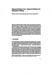
Fig. 1.
The humanoid robot James.
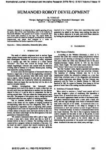
III. T HE ROBOTIC SETUP The experiments described in this paper were carried out on the robot James (see figure 1 and [21] for more details). James is an upper body humanoid robot which consists of 22 DOFs, actuated by a total of 23 motors. Torque is transmitted to the joints by belts and stainless-steel tendons. The head is equipped with two eyes, which can pan and tilt independently (4 DOFs), and is mounted on a 3-DOF neck. The arm has 7 DOFs: three of them are located in the shoulder, one in the elbow and three in the wrist. The hand has five fingers and is under-actuated with a total of 20 degrees of freedom controlled by 8 motors. The head structure has a total of 7 degrees of freedom, actuated by 8 motors. Four of these motors are used to independently actuate the pan and tilt movements of the left and right eyes. To achieve a more human-like motion our strategy was to couple the movements of the eyes. We used common tilt αtc , vergence αvd and version αvc . The neck has three degrees of freedom, denoted θy , θp and θr for yaw, pitch and roll respectively. To summarize, the variables relevant to understand the remainder of the paper are: ¤> the6 head joints qhead = £ c c d αt αv αv θy θp θr ∈ R and the first four arm joints (3 d.o.f. shoulder and elbow) denoted qarm ∈ R4 . IV. G AZE CONTROL The crucial aspect in the control of gaze concerns the redundancy of the head. Let ur and vr be the coordinates of the target on the right image plane. Similarly, let ul and vl be the coordinates of the target on the left image plane (see Figure 2). The values of ur , vr , ul , vl are the output of a visual module which detects the target in the image planes. Directing gaze toward the target consists in moving the neck and the eyes so as to obtain ur = 0, £ vr = 0, ul = 0,¤>vl = 0. ˜ target = ur vr ul vl ∈ R4 Let us define the vector u corresponding to the target location in the image planes. Under reasonable assumptions, we do not need to impose simultaneously the four conditions ur = 0, vr = 0, ul = 0, vl = 0. Our control task as the problem of £ can be redefined ¤> controlling utarget = ur ul vl ∈ R3 to zero. Clearly, the task specification does not constrain all the head degrees
vl
vr ul
ur
Fig. 2. Two typical images taken from the cameras mounted on the eyes of the robot (resolution 320×240). The coordinates of the target (the blue ball) on the image planes will be denoted ul , vl , and ur , vr (respectively left and right cameras).
of freedom (we are imposing 3 constraints but we have 6 free variables available). We solve this “redundancy problem” by using two controllers for the eyes and the neck. The former controls the eyes version and common tilt to track the object, while the latter controls neck yaw and pitch to maintain the eyes “centered” within the neck. Mathematically the above strategy can be implemented as follows: ½ c ½ c α˙v = Kp (ul + ur ) α˙t = Kt (vl + vr ) , (1) , c θ˙y = Ky αv θ˙p = Kr αtc where αvc and αtc are the eyes tilt and common version and where θy and θp are the yaw and pitch movement of the neck. In the proposed control scheme, the vergence degree of freedom αvd , which corresponds to the distance of the target does not influence the neck position and is therefore controlled separately from the neck: α˙vd
=
Kp (ul − ur ).
(2)
Finally, the neck roll degree of freedom θr is maintained fixed, i.e. θrd = 0. The proposed control strategy allows us to asymptotically fixate the target (ul → 0, vl → 0, ur → 0 which implies vr → 0) while, at least within the mechanical limits of the head, also guaranteeing a straight gaze (αvc → 0, αtc → 0). V. R EACHING In this section, we describe the two approaches we followed to solve the reaching task on our robot. The first method uses the forward mapping between the arm joint space and the three dimensional position of the hand represented in the head reference frame. The second method uses a visual servoing technique to control the speed of the arm to minimize the position of the hand in the image plane with respect to a desired target (the fixated object). A. Open Loop Reaching Suppose that the robot is tracking a target as described in Section IV. In the assumption of perfect tracking (the visual error is zero), the three dimensional spatial position ˜ target ∈ of the target with respect to the robot, denoted x
3 R of the ¤ head configuration qhead = £ , is a function > d θy θp θr αv αvc αtc ∈ R6 . However, the repre˜ target , in terms of the sentation of the target position, x full head configuration, qhead , is redundant. Specifically, the same target position can be represented by different head configurations. To obtain a one to one mapping between the target position and the head configuration we have to analyze the gaze controller. The latter maintains θr stationary (θrd = 0) and poses additional constraints on the head joints. In particular the controller minimizes αtc and αvc (see equation (1)) so that they converge to zero (αtc → 0 and αvc → 0). Ideally, after fixation is achieved, we have £ ¤> qhead = θy θp 0 αvd 0 0 ∈ R6 . Since there exists a one to one mapping between the three dimensional position ˜ target and the three non-zero variables θy , θp of the target x £ ¤> and αvd , we can define xtarget = θy θp αvd ∈ R3 . This new variable xtarget ∈ R3 uniquely codes the spatial position of the target in a way that resembles a three dimensional polar representation. In particular θy and θp code azimuth and elevation, while distance is substituted with αv (the vergence angle). If the robot tracks the hand, the same subset of the head joint space can be used to code ¤ the spatial location of £ > ∈ R3 . Under these the hand: xhand = θy θp αvd assumptions, the forward mapping farm relates the arm configuration qarm with the position of the hand xhand :
xhand = farm (qarm ),
farm : R4 −→ R3 .
(3)
In the next section we show how a neural network could be trained to approximate farm . Suppose now that the robot is fixating a target and that we want to control the robot to reach for it. Formally the problem can be formulated as determining the value of qarm which solves the following optimization problem: 2
min kxhand − xtarget k ,
qarm
(4)
where xtarget is measured from the encoders of the head, while xhand is computed from qarm through Eq. (3). Given the redundancy of the arm kinematics this minimization has infinite solutions. We constrained the problem by forcing one of the joints, for example joint number 2 (one of the shoulder joints), to remain as close as possible to a predefined value q20 : h i 2 2 min kxhand − xtarget k + (qarm,2 − q20 ) . (5) qarm
The optimization of (5) can be performed numerically using various algorithms. In our implementation, we used the downhill simplex method [22]. B. Learning the open loop reaching To learn the forward map of Eq. (3) we programmed the robot to perform random movements with the arm
xhand = fˆarm (qarm ) ,
(6)
1
10
3
MSE [pixels2/deg2]
10
MSE [deg2]
(chosen to uniformly sample a predefined region in the robot workspace). During this “exploratory” phase the robot tracked the hand, and collected samples of the form: ¡ i ¢ qarm , xihand i=0,1... . A neural network was then trained to learn the relation:
2
10
1
10
0
10
0
500
1000
1500
2000
samples
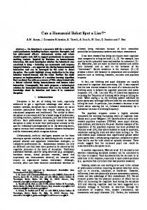
which approximates Eq. (3). In the experiment reported in this paper we collected a data set of about 2890 samples that we divided in a training set (Ntrain = 2168 samples) and a test set (Ntest = 725 samples). The neural network we employed was the Receptive Field Weighted Regression model proposed by [23]. This network implements an online learning method, meaning that a learning step is performed every time a new sample is presented to the network. All samples in the training set were shown to the network in a random order. After each training step the performance of the network was validated on the whole test set, by computing the Mean Squared Error (MSE) between each sample in the test set, and the corresponding network output. The plot in figure 3 shows the trend of the error on the test set during learning. At the end of the training the network reached the performance of MSE = 5.7 deg 2 (with STD = 10.4 deg 2 ). In the experiment reported in this paper the network was trained offline. This was done to simplify the analysis of the results and to perform cross-validation on a predefined test set. However, the learning algorithm we used is purely incremental (each sample was shown to the network only once and immediately discarded), so in this regard it would be straightforward to convert the same approach to an online implementation. C. Closed Loop Reaching If the robot could visually measure the distance between the hand and the target, reaching could also be solved visually by implementing a closed control loop. This consists in performing a preliminary (open loop) reaching movement and then refining the action by visually correcting any residual error. We know that the Jacobian matrix relates arm velocities ˙ arm with hand velocities in the image plane u˙ hand = q £ ¤> u˙ r u˙ l v˙ l : ˜ (qarm , qhead ) q˙ arm , u˙ hand = J
(7)
˜ ∈ R3×4 depends on both the configuration of the where J arm and the head. In practice, assuming sufficiently small arm movements ∆qarm , we can use the following approximation: ˜ (qarm , qhead ) ∆qarm , ∆uhand = J
(8)
where ∆uhand is the image plane displacement resulting from the arm movement ∆qarm . Due to the additional constraints
10
0
40
80
120
160
samples
Fig. 3. Left: learning of the arm forward function. Right: learning the arm jacobian. The plots represent the MSE on the test set during learning. See text for more details
posed by the head tracker, we showed that only a subset of qhead , xtarget , is sufficient to uniquely identify the position of the head, so we can rewrite equation (8) as: ˜ (qarm , xtarget ) ∆qarm , ∆uhand = J
˜ ∈ R3×4 . (9) J
Moreover, after the preliminary open loop reaching movement, we know that xtarget = farm (qarm ) so that Eq. (9) can be further simplified to: ∆uhand = J (qarm ) ∆qarm ,
J ∈ R3×4
(10)
where J depends only on the arm joint configuration qarm . Suppose now that the robot has to reach for an object, whose visual position is represented by utarget . To solve this problem the controller of the arm needs to compute the arm command which minimizes the error e = 2 kuhand − utarget k . When the head tracker has achieved 2 convergence on the object, utarget ≈ 0 and e ≈ kuhand k . Due to the redundancy of the arm, the minimization of e can have infinite solutions. Among them, the minimum norm solution corresponds to the minimum joint speeds, that is: q˙ arm = −k · J# uhand ,
J# ∈ R4×3 ,
(11)
where J# is the Moore-Penrose pseudo-inverse of J. In practice xtarget = farm (qarm ) is estimated through Eq. ˆ # will be available. 6, so only an approximated value J ˆ # · J > 0 [24]. Convergence is guaranteed if J D. Learning the Arm Jacobian As described in Section V-B, the robot moves the arm randomly, while maintaining gaze on the hand. At the end of each movement j the arm is in a configuration qjarm , while the eyes are fixating the hand (uhand ≈ 0). Each arm configuration corresponds to a different value ¡ ¢ of Jj = J qjarm . Now the robot inhibits the head tracker and performs a sequence m of small arm movek ments ∆q ¢ uhand of small amounts ¡ armk which kperturb k ∆uhand : ∆uhand , ∆qarm k=0,1...,m . All m perturbations ∆ukhand and ∆qkarm are linearly related through Ji as described in Eq. (9). From these m observations we can derive a least squares estimation of Jj from which, in turn, we can compute the pseudo-inverse J# j .
10
10
0
0
−10
−10
−20
100
100
50
50
0
0
−50
−50
−20 −100
−30 −20
−15
−10
−5
0
Left eye
5
−30 −25
−20
−15
−10
Right eye
−5
60
40
40
0
Left eye
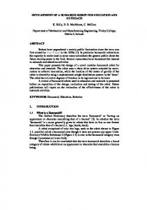
Fig. 4. Open loop performance, for different choices of the redundant variable q20 (image plane errors uhand , in pixels). On the horizontal axis ur and ul ; vertical axis vr and vl (always in pixels). The hand position in the image plane is represented by the small circles. Each circle corresponds to a different open loop movement, i.e. a different value of q20 . 60
−100 −100
0
100
−100
0
0
−20
−20
−40 −60
−40
−20
Left eye
0
20
−40 −60
0
−50
−100 1
2 time [s]
3
Left eye −40
−20
0
Right eye
4
1
2 time [s]
3
4
Right eye
20
Re-iterating this ³procedure leads ´ to the collection of a . An approximation series of examples: qjarm , J# j j=0,1...
ˆ # of J# is finally obtained by training a neural network: J g : R4 −→ R12 ,
0
−50
−100
Fig. 5. Traces of different closed loop control actions. Each trace correspond to a different Cartesian position of the target to be reached (which is always at the center of the image planes). All the traces end up in the image center thus indicating that the visual errors are completely eliminated by the closed loop controller.
g (qarm ) ,
50 Error [pixel]
Error [pixel]
20
100
Fig. 6. Movement of the hand on the image planes (320×240) during the execution of different reaching actions. Solid line: closed loop. Dashed trace: open loop. Clearly the open loop movement drives the hand to the target (the image centers) with a relatively small error. The closed loop phase reduces this error to zero.
50
20
0
Right eye
(12)
ˆ # ∈ R4×3 . whose output components are the coefficients of J We report here the result of a learning session. The robot explored 210 different arm positions qjarm randomly distributed within a region of the workspace. In each of these positions the robot executed m = 10 perturbations ∆qkarm and estimated an example J# j for the neural network. Overall we collected 210 samples for J# . We trained the neural network on a subset of Ntrain = 158 elements (training set); each sample was shown to the network only once and then discarded. Following each training step, we evaluated the performance of the network by computing MSE on the remaining Ntest = 52 elements (test set). At the end of 2 the training the error on the test set was MSE = 2 pixels deg 2 2
(STD = 7.1 pixels deg 2 ). Figure 3 reports the plot of the error during learning. VI. R ESULTS In this section we report the results of the experiments we carried out to quantify the performance of the reaching movements. Following the proposed strategy, in order to reach for the target we first need to fixate it, i.e. utarget = 0.
Fig. 7. Time response of the closed loop and open loop strategy. Solid lines: ur and ul . Dashed lines: vr and vl . Remarkably, the open loop phase is faster but does not drive the hand exactly on the target. The closed loop is slower but more accurate.
Using the available sensor (i.e. vision) the best we can do to precisely reach the target is moving the hand to the fixation point, i.e. uhand −→ 0. Clearly, the image plane distance e = kuhand − utarget k can be used as a rough estimate of the reaching precision, i.e. of the Cartesian distance between the target to be reached and the position of the hand. The first attempt to reach the target consists in using (5) to choose the arm configuration qarm which brings the hand to the center of the image planes. Clearly, if the forward kinematic function (3) were perfectly represented and if the target were reachable, then we would have xhand = xtarget , which implies that the target-hand Cartesian distance is zero, e = 0 (see Section V for details). In practice, the model (3) cannot exactly represent the system’s kinematics , therefore it is not guaranteed that after the movement execution e = 0. Figure 4 shows the image plane errors after the execution of the open loop movement. The plot has been obtained by fixating a target and performing a series of open loop movements. Each open loop movement was different because (5) was solved by choosing a different value q20 . The residual image plane errors can be reduced by a visual closed loop control strategy. This control strategy moves the arm to progressively drive the hand position in the image planes (uhand ) to zero. Figures 5, 6 and 7 show how the hand is actually driven to the exact image center in both the image planes. The closed loop controller improves the accuracy of the reaching movement, but at the cost of a slower execution speed (see Figure 7). Moreover, it is important to notice the quasi-linearity of the path followed by the hand (see Figure
5). This linearity denotes a good accuracy of the learned Jacobian. VII. C ONCLUSIONS In this paper we have described the implementation of a reaching behavior that integrates together an open loop and a closed loop controller. The open loop controller allows the robot to perform faster movements and does not require visual feedback from the hand. When sight of the hand is available the closed loop controller allows for precise positioning of the hand in the image plane. We describe an exploration strategy by means of which the robot autonomously acquires the forward motor map and the visual Jacobian transformations. Among other things this strategy allows the estimation of the eye-to-hand visual Jacobian of the robot. The estimation of the Jacobian is a well studied task for which several solutions have been proposed [17]–[19]. None of these works, however, address the problem of the redundancy of both the head and the arm. In the experiments reported here the estimation of the Jacobian is performed with good accuracy for a subset of the arm workspace and for different head postures. We believe this is an important contribution with respect to the state of the art. We do not rely on prior information about the kinematic structure of the robot. The only major simplification was that we used a color marker to visually localize the hand of the robot. Our assumption is that the hand localization/identification is a separate problem that needs to be solved before learning to reach. Previous work have suggested procedures by which the robot could autonomously learn to solve this task [25], [26]. It will be interesting to see how these approaches can be integrated with the work described in this paper. ACKNOWLEDGEMENT The work presented in this paper has been supported by the ROBOT C UB project (IST-2004-004370), funded by the European Commission through the Unit E5 “Cognitive Systems”. Moreover, it has been partially supported by N EUROBOTICS, a European FP6 project (IST-2003-511492) and C ONTACT (NEST 5010). R EFERENCES [1] V. Gallese, L. Fadiga, L. Fogassi, , and G. Rizzolatti, “Action recognition in the premotor cortex,” Brain, vol. 119, pp. 593–609, 2006. [2] R. Klatzky and S. Lederman, “Hand movements: A window into haptic object recognition,” Cognitive Psychology, vol. 19, pp. 342–368, 1987. [3] E. Bushnell and J. Boudreau, “Motor development and the mind: The potential role of motor abilities as a determinant of aspects of perceptual development,” Child Dev., vol. 64, no. 4, pp. 1005–1021, 1993. [4] P. Fitzpatrick, A. Needham, L. Natale, and G. Metta, “Shared challenges in object perception for robots and infants,” Journal of Infant and Child Development, accepted for publication.
[5] S. A. Hutchinson, G. D. Hager, and P. I. Corke, “A tutorial on visual servo control,” IEEE Trans. Robotics and Automation, vol. 12, no. 5, pp. 651–670, October 1996. [Online]. Available: citeseer.ist.psu.edu/hutchinson96tutorial.html [6] M. R. Blackburn and H. G. Nguyen, “Learning in robot vision directed reaching: A comparison of methods,” in ARPA Image Understanding Workshop, Monterey, CA, USA, November 1994. [7] G. Metta, G. Sandini, and J. Konczak, “A developmental approach to visually-guided reaching in artificial systems,” Neural Networks, vol. 12, pp. 1413–1427, 1999. [8] R. Clifton and M. C. D.W. Muir, D.H. Ashmead, “Is visually guided reaching in early infancy a myth?” Child Dev., vol. 64, no. 4, pp. 1099–110, 1993. [9] D. Ashmead, M. McCarty, L. Lucas, and M. Belvedere, “Visual guidance in infants’ reaching toward suddenly displaced targets,” Child Dev., vol. 64, no. 4, pp. 1111–27, 1993. [10] M. Flanders, L. Daghestani, and A. Berthoz, “Reaching beyond reach,” Experimental Brain Research, vol. 126, no. 1, pp. 19–30, 1999. [11] J. M. Hollerbach and C. W. Wampler, “The calibration index and taxonomy for robot kinematic calibration methods,” International Journal of Robotics Research, vol. 15, no. 6, pp. 573–591, 1996. [12] R. Tsai and R. Lenz, “Real time versatile robotics hand/eye calibration using 3D machine vision,” in International conference on Robotics and Automation, vol. 1, April 1988. [13] Y. Ma, S. Soatto, J. Kosecka, and S. S. Sastry, An Invitation to 3D Vision: From Images to Geometric Models. SpringerVerlag, 2003. [14] N. Andreff, R. P. Horaud, and B. Espiau, “Robot hand-eye calibration using structure from motion,” International Journal of Robotics Research, vol. 20, no. 3, pp. 228–248, Mar 2001. [15] D. Bennett and J. Hollerbach, “Autonomous calibration of single-loop closed kinematic chainsformed by manipulators with passive endpoint constraints,” IEEE Transactions on Robotics and Automation, vol. 7, no. 5, pp. 597–606, October 1991. [16] M. Lopes and J. Santos-Victor, “Learning sensory-motor maps for redundant robots,” in IEEE/RSJ International Conference for Intelligent Robots and Systems, Beijin, China, October 2006. [17] K. Hosoda and M. Asada, “Versatile visual servoing without knowledge of true Jacobian,” in Proc. IROS, Sep. 1994. [18] N. Mansard, M. Lopes, J. Santos-Victor, and F. Chaumette, “Jacobian learning methods for tasks sequencing in visual servoing,” in IEEE/RSJ Int. Conf. on Intelligent Robots and Systems, IROS’06, Beijing, China, October 2006, pp. 4284–4290. [19] J.-T. Laprest, F. Jurie, M. Dhome, and F. Chaumette, “An efficient method to compute the inverse jacobian matrix in visual servoing,” in IEEE Int. Conf. on Robotics and Automation, ICRA’04, vol. 1, New Orleans, LA, April 2004, pp. 727–732. [20] B. Scassellati and G. Sun, “A fast and efficient model for learning to reach,” International Journal of Humanoid Robotics, vol. to appear, 2007. [21] L. Jamone, F. Nori, G. Metta, and G. Sandini, “James: A humanoid robot acting over an unstructured world,” in IEEE-RAS International Conference on Humanoid Robots, Genova, Italy, December 2006. [22] J. A. Nelder and R. Mead, “A simplex method for function minimization,” Computer journal, vol. 7, pp. 308–313, 1965. [23] S. Schaal and C. Atkenson, “Constructive incremental learning from only local information,” Neural Computation, vol. 8, no. 10, pp. 2047– 2084, 1998. [24] C. Samson, M. L. Borgne, and B. Espiau, Robot Control:The Task Function Approach. Clarendon, 1991. [25] L. Natale, F. Orabona, G. Metta, and G. Sandini, “Exploring the world through grasping: a developmental approach,” in 6th CIRA Symposium, Espoo, Finland, June 2005. [26] A. Edsinger and C. Kemp, “What can i control? a framework for robot self-discovery,” in 6th International Conference on Epigenetic Robotics, Paris, France, September 2006.