Entity Relationship Modelling. ➜ The Entity-Relationship Model. Entities.
Relationships ... Translates readily to relational schema for database design.
University of Toronto
Department of Computer Science
Lecture 12: Entity Relationship Modelling
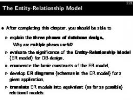
The Entity-Relationship Model Entities Relationships Attributes
Constraining the instances Cardinalities Identifiers Generalization
© 2004-5 Steve Easterbrook. This presentation is available free for non-commercial use with attribution under a creative commons license.
1
University of Toronto
Department of Computer Science
The Entity Relationship Model
Entity-Relationship Schema Describes data requirements for a new information system Direct, easy-to-understand graphical notation Translates readily to relational schema for database design But more abstract than relational schema E.g. can represent an entity without knowing its properties
comparable to UML class diagrams
Entities: classes of objects with properties in common and an autonomous existence E.g. City, Department, Employee, Purchase and Sale
An instance of an entity is an object in the class represented by the entity E.g. Stockholm, Helsinki, are examples of instances of the entity City
Relationships: logical links between two or more entities.
E.g. Residence is a relationship that can exist between the City and Employee
An instance of a relationship is an n-tuple of instances of entities
E.g. the pair (Johanssen,Stockholm), is an instance in the relationship Residence.
© 2004-5 Steve Easterbrook. This presentation is available free for non-commercial use with attribution under a creative commons license.
2
Department of Computer Science
University of Toronto
Examples Adapted from chapter 5 of Atzeni et al, “Database Systems” McGraw Hill, 1999
© 2004-5 Steve Easterbrook. This presentation is available free for non-commercial use with attribution under a creative commons license.
3
Department of Computer Science
University of Toronto
Example Instances for Exam Adapted from chapter 5 of Atzeni et al, “Database Systems” McGraw Hill, 1999
Exam © 2004-5 Steve Easterbrook. This presentation is available free for non-commercial use with attribution under a creative commons license.
4
Department of Computer Science
University of Toronto
What Does An ER Diagram Really Mean? Adapted from chapter 5 of Atzeni et al, “Database Systems” McGraw Hill, 1999
Course
Meets
Room
Course and Room are entities. Their instances are particular courses (eg CSC340F) and rooms (eg MS2172)
Meets is a relationship. Its instances describe particular meetings. Each meeting has exactly one associated course and room
Course instances
Meets instances
Room instances
© 2004-5 Steve Easterbrook. This presentation is available free for non-commercial use with attribution under a creative commons license.
5
University of Toronto
Department of Computer Science
Recursive Relationships Adapted from chapter 5 of Atzeni et al, “Database Systems” McGraw Hill, 1999
An entity can have relationships with itself…
If the relationship is not symmetric… …need to indicate the two roles that the entity plays in the relationship.
© 2004-5 Steve Easterbrook. This presentation is available free for non-commercial use with attribution under a creative commons license.
6
University of Toronto
Department of Computer Science
Ternary Relationships Adapted from chapter 5 of Atzeni et al, “Database Systems” McGraw Hill, 1999
© 2004-5 Steve Easterbrook. This presentation is available free for non-commercial use with attribution under a creative commons license.
7
University of Toronto
Department of Computer Science
AND/XOR Relationships “Each Order either contains a part or requests a service, but not both”
“For any given order, whenever there is at least one invoice there is also at least one shipment and vice versa”
© 2004-5 Steve Easterbrook. This presentation is available free for non-commercial use with attribution under a creative commons license.
8
Department of Computer Science
University of Toronto
Attributes Adapted from chapter 5 of Atzeni et al, “Database Systems” McGraw Hill, 1999
associates with each instance of an entity (or relationship) a value belonging to a set (the domain of the attribute). The domain determines the admissible values for the attribute.
© 2004-5 Steve Easterbrook. This presentation is available free for non-commercial use with attribution under a creative commons license.
9
University of Toronto
Department of Computer Science
Composite Attributes Adapted from chapter 5 of Atzeni et al, “Database Systems” McGraw Hill, 1999
These group attributes of the same entity or relationship that have closely connected meanings or uses.
© 2004-5 Steve Easterbrook. This presentation is available free for non-commercial use with attribution under a creative commons license.
10
University of Toronto
Department of Computer Science
Schema with Attributes Adapted from chapter 5 of Atzeni et al, “Database Systems” McGraw Hill, 1999
© 2004-5 Steve Easterbrook. This presentation is available free for non-commercial use with attribution under a creative commons license.
11
Department of Computer Science
University of Toronto
Cardinalities Adapted from chapter 5 of Atzeni et al, “Database Systems” McGraw Hill, 1999
Cardinalities constrain participation in relationships maximum and minimum number of relationship instances in which an entity instance can participate. E.g.
cardinality is any pair of non-negative integers (a,b) such that a≤b. If a=0 then entity participation in a relationship is optional If a=1 then entity participation in a relationship is mandatory. If b=1 each instance of the entity is associated at most with a single instance of the relationship If b=“N” then each instance of the entity is associated with an arbitrary number of instances of the relationship.
© 2004-5 Steve Easterbrook. This presentation is available free for non-commercial use with attribution under a creative commons license.
12
Department of Computer Science
University of Toronto
Cardinality Example Adapted from chapter 5 of Atzeni et al, “Database Systems” McGraw Hill, 1999
“A course meets twice a week”
Course
(2,2)
“A day can have an unlimited number of meetings”
Meets
(0,N)
(0,40)
Room
“A room can have up to 40 meetings per week”
Day
© 2004-5 Steve Easterbrook. This presentation is available free for non-commercial use with attribution under a creative commons license.
13
Department of Computer Science
University of Toronto
Instantiating ER diagrams Adapted from chapter 5 of Atzeni et al, “Database Systems” McGraw Hill, 1999
An ER diagram specifies what states are possible in the world being modeled Course
(2,2)
Meets
(0,40)
Room
Illegal Instantiations
© 2004-5 Steve Easterbrook. This presentation is available free for non-commercial use with attribution under a creative commons license.
14
Department of Computer Science
University of Toronto
Cardinalities of Attributes Adapted from chapter 5 of Atzeni et al, “Database Systems” McGraw Hill, 1999
Attributes can also have cardinalities To describe the minimum and maximum number of values of the attribute associated with each instance of an entity or a relationship. The default is (1,1) Optional attributes have cardinality (0,1)
Multi-valued attribute cardinalities are problematic Usually better modelled with additional entities linked by one-to-many (or manyto-many) relationships
© 2004-5 Steve Easterbrook. This presentation is available free for non-commercial use with attribution under a creative commons license.
15
University of Toronto
Identifiers
Department of Computer Science
(also known as “keys”)
Adapted from chapter 5 of Atzeni et al, “Database Systems” McGraw Hill, 1999
How to uniquely identify instances of an entity? An identifier may formed by one or more attributes of the entity itself If attributes of an entity are not sufficient to identify instances unambiguously, other entities can be involved in the identification A relationships is identified using identifiers for all the entities it relates
E.g. the identifier for the relationship (Person-) Owns(-Car) is a combination of the Person and Car identifiers.
internal, single-attribute
external, multi-attribute
internal, multi-attribute
© 2004-5 Steve Easterbrook. This presentation is available free for non-commercial use with attribution under a creative commons license.
16
University of Toronto
Department of Computer Science
Notes on Identifiers Adapted from chapter 5 of Atzeni et al, “Database Systems” McGraw Hill, 1999
Identifiers and cardinality: An identifier can involve one or more attributes, provided that each has (1,1) cardinality An external identifier can involve one or more entities, provided that each is a member of a relationship to which the entity to identify participates with cardinality (1,1)
Cycles An external identifier can involve an entity that is in its turn identified externally, as long as cycles are not generated;
Multiple identifiers Each entity must have at least one (internal or external) identifier An entity can have more than one identifier
Note: if there is more than one identifier, then the attributes and entities involved in an identification can be optional (minimum cardinality equal to 0).
© 2004-5 Steve Easterbrook. This presentation is available free for non-commercial use with attribution under a creative commons license.
17
University of Toronto
Department of Computer Science
Schema with Identifiers Adapted from chapter 5 of Atzeni et al, “Database Systems” McGraw Hill, 1999
© 2004-5 Steve Easterbrook. This presentation is available free for non-commercial use with attribution under a creative commons license.
18
University of Toronto
Department of Computer Science
Understanding Identifier Choices
© 2004-5 Steve Easterbrook. This presentation is available free for non-commercial use with attribution under a creative commons license.
19
University of Toronto
Department of Computer Science
Generalizations Adapted from chapter 5 of Atzeni et al, “Database Systems” McGraw Hill, 1999
Show “is-a” relationships between entities
Inheritance: Every instance of a child entity is also an instance of the parent entity Every property of the parent entity (attribute, identifier, relationship or other generalization) is also a property of a child entity
© 2004-5 Steve Easterbrook. This presentation is available free for non-commercial use with attribution under a creative commons license.
20
University of Toronto
Department of Computer Science
Types of Generalizations Adapted from chapter 5 of Atzeni et al, “Database Systems” McGraw Hill, 1999
Total generalizations: …every instance of the parent entity is an instance of one of its children Shown as a solid arrow (otherwise: Partial, shown as an unfilled arrow)
Exclusive generalizations: …every instance of the parent entity is at most an instance of one of its children (otherwise: overlapping)
© 2004-5 Steve Easterbrook. This presentation is available free for non-commercial use with attribution under a creative commons license.
21
University of Toronto
The E-R Meta-Model
Department of Computer Science
(as an E-R Diagram)
Adapted from chapter 5 of Atzeni et al, “Database Systems” McGraw Hill, 1999
© 2004-5 Steve Easterbrook. This presentation is available free for non-commercial use with attribution under a creative commons license.
22
University of Toronto
Department of Computer Science
Summary: UML vs ERD
ER diagrams are similar to UML Class diagrams Class diagrams emphasize class hierarchies and operations ER diagrams emphasize relationships and identity But you only need one for any given problem analysis!
ER provides richer notation for database concepts: ER diagrams allow N-ary relationships
(UML Class diagrams only allow binary relationships)
ER diagrams allow multi-valued attributes ER diagrams allow the specification of identifiers
Choice may depend on implementation target: Class diagrams for Object Oriented Architecture ER diagrams for Relational Databases But this only matters if you are using them for blueprints For sketches, familiarity with notation is more important
© 2004-5 Steve Easterbrook. This presentation is available free for non-commercial use with attribution under a creative commons license.
23