Lectures on “Introduction to Geophysical Fluid Dynamics”. Pavel Berloff.
Department of Mathematics, Imperial College London. • Idea of the lectures is to
provide ...
Lectures on “Introduction to Geophysical Fluid Dynamics” Pavel Berloff Department of Mathematics, Imperial College London • Idea of the lectures is to provide a relatively advanced-level course that builds up on the existing introductory-level fluid dynamics courses. The lectures target an audience of upper-level undergraduate students, graduate students, and postdocs. • Main topics: (1) Introduction (2) Governing equations (3) Geostrophic dynamics (4) Quasigeostrophic theory (5) Ekman layer (6) Rossby waves (7) Linear instabilities (8) Ageostrophic motions (9) Transport phenomena (10) Nonlinear dynamics and wave-mean flow interactions • Suggested textbooks: (1) Introduction to geophysical fluid dynamics (Cushman-Roisin and Beckers); (2) Fundamentals of geophysical fluid dynamics (McWilliams); (3) Geophysical fluid dynamics (Pedlosky); (4) Atmospheric and oceanic fluid dynamics (Vallis).
Motivations • Main motivations for the recent rapid development of Geophysical Fluid Dynamics (GFD) include the following very important, challenging and multidisciplinary set of problems: — Earth system modelling, — Predictive understanding of climate variability (emerging new science!), — Forecast of various natural phenomena (e.g., weather), — Natural hazards, environmental protection, natural resources, etc. What is GFD? • Most of GFD is about dynamics of stratified and turbulent fluid on giant rotating sphere. On smaller scales GFD is just the classical fluid dynamics with geophysical applications. — Other planets and some astrophysical fluids (e.g., stars, galaxies) are also included in GFD. • GFD combines applied math and theoretical physics. It is about mathematical representation and physical interpretation of geophysical fluid motions. • Mathematics of GFD is heavily computational, even relative to other branches of fluid dynamics (e.g., modelling of the ocean circulation and atmospheric clouds are the largest computational problems in the history of science). — This is because lab experiments (i.e., analog simulations) can properly address only tiny fraction of interesting questions (e.g., small-scale waves, convection, microphysics). • In geophysics theoretical advances are often GFD-based rather than experiment-based, because the real field measurements are extremely complex, difficult, expensive and often impossible. Let’s overview some geophysical phenomena of interest...
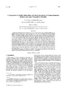
An image of the Earth from space:
• Earth’s atmosphere and oceans are the main but not the only target of GFD
This is not an image of the Earth from space...
...but a visualized solution of the mathematical equations!
• Atmospheric cyclones and anticyclones constitute most of the midlatitude weather. This cyclone is naturally visualized by clouds:
• Modelling clouds is notoriously difficult problem in atmospheric science.
• Tropical cyclones (hurricanes and typhoons) are a coupled ocean-atmosphere phenomenon. These are powerful storm systems characterized by low-pressure center, strong winds, heavy rain, and numerous thunderstorms. Hurricane Katrina approaches New Orleans:
• Ocean-atmosphere coupling: Ocean and atmosphere exchange momentum, heat, water, radiation, aerosols, and greenhouse gases. Ocean-atmosphere interface is a very complex two-sided boundary layer:
Ocean currents are full of transient mesoscale eddies:
• Mesoscale eddies are dynamically similar to atmospheric cyclones and anticyclones, but much smaller and more abundant. They are the “oceanic weather”. • Modelling the eddies and their effects is very important and challenging problem.
Submesoscale eddies around an island:
• Submesoscale motions are geostrophically and hydrostatically unbalanced, which means that they are less affected by the rotation and more 3D-like.
• Many GFD processes are influenced by coasts and topography (e.g., coastal currents, upwellings, tidal mixing, lee waves).
• Turbulence operates on all scales down to millimeters, but on smaller scales effects of planetary rotation and vertical stratification weaken and GFD turns into classical fluid dynamics.
• GFD deals with different waves operating on scales from meters to thousands of kilometers. • Problem of internal gravity wave breaking is very important and challenging. Breaking surface gravity waves:
• Tsunami is another example of the surface gravity wave. Evolution of a tsunami predicted by the high-accuracy shallow-water modelling:
• GFD is involved in problems with formation and propagation of ice...
⇐= Flowing glacier
Formation of marine ice =⇒
...and in modelling material transport:
• GFD applies beyond the Earth, to the atmospheres of other planets. Circulation of the Jupiter’s weather layer:
Convection clouds on Jupiter (science fiction art by Andrew Stewart):
• Some theories argue that the alternating jets on giant gas planets are driven by deep convective plumes which feed upscale cascade of energy.
• MagnetoHydroDynamics (MHD) of stars naturally extends the realm of GFD Beautiful example of coronal rain on the Sun:
• Representation of fluid flows Let’s consider a flow consisting of fluid particles. Each particle is characterized by its position r and velocity u vectors: ∂r(a, t) dr(t) = = u(r, t) , dt ∂t
r(a, 0) = a
• Trajectory (pathline) of an individual fluid particle is “recording” of the path of this particle over some time interval. Instantaneous direction of the trajectory is determined by the corresponding instantaneous streamline. • Streamlines are a family of curves that are instantaneously tangent to the velocity vector of the flow u = (u, v, w). Streamline shows the direction a fluid element will travel in at any point in time. A parametric representation of just one streamline (here s is coordinate along the streamline) at some moment in time is Xs (xs , ys , zs ) : � ∂x � ∂x � ∂y dXs ∂zs � ∂zs � ∂ys � s s s −j w +k v =0 × u(xs , ys , zs ) = 0 =⇒ i w −v −u −u ds ∂s ∂s ∂s ∂s ∂s ∂s dys dzs dxs = = u v w For 2D non-divergent flows the velocity streamfunction can be used to plot streamlines: ∂ψ ∂ψ u = −∇×ψ , ψ = (0, 0, ψ) , u = (u, v, 0) =⇒ u=− , v= ∂y ∂x =⇒
• Streakline is the collection of points of all the fluid particles that have passed continuously through a particular spatial point in the past. Dye steadily injected into the fluid at a fixed point extends along a streakline. — If flow is stationary, that is ∂/∂t ≡ 0, then streamlines, streaklines and trajectories coincide. • Timeline is the line formed by a set of fluid particles that were marked at the same time, creating a line or a curve that is displaced in time as the particles move. • Lagrangian framework: Point of view such that fluid is described by following fluid particles. Interpolation problem, not optimal use of information. • Eulerian framework: Point of view such that fluid is described at fixed positions in space. Nonlinearity problem.
GOVERNING EQUATIONS • Complexity: These equations are sufficient for finding a solution but are too complicated to solve; they are useful only as a starting point for GFD analysis. • Art of modelling: Typically the governing equations are approximated analytically and, then, solved approximately (by analytical or numerical methods); one should always keep track of all main assumptions and approximations. • Continuity of mass: Consider a fixed infinitesimal volume of fluid (Eulerian view) and flow of mass through its surfaces.
∂ρ + ∇·(ρu) = 0 ∂t
or
Dρ = −ρ∇·u ; Dt
D ∂ = + u·∇ Dt ∂t
←− material derivative
Note: if fluid is incompressible (i.e., ρ = const), then ∇·u = 0. • Material derivative operating on X gives the rate of change of X with time following the fluid element (i.e., subjected to a space-andtime dependent velocity field). It is a link between Eulerian and Lagrangian descriptions of fluid. • Tendency term, ∂X/∂t, represents the rate of change of X at a point which is fixed in space (and occupied by different fluid particles at different times). Changes of X are observed by stand-still observer. • Advection term, u·∇X, represents changes of X due to movement with velocity u (or, flow supply of X to a fixed point). Additional changes of X experienced by observer swimming with velocity u.
• Material tracer equation (evolution equation for composition): By similar argument, for any material tracer (e.g., chemicals, aerosols, gases) concentration τ (amount per unit mass), the evolution equation is ∂(ρτ ) + ∇·(ρτ u) = ρ S (τ ) , ∂t where S (τ ) stands for all the non-conservative sources and sinks of τ (e.g., boundary sources, molecular diffusion, reaction rate). The tracer diffusion is generally added and represented by ∇·(κ ∇τ ). • Momentum equation: Write Newton’s Second Law in the fixed frame of reference, for infinitesimal volume of fluid δV and force F acting on a unit volume: D (ρuδV ) = F δV Dt
=⇒
u
D D (ρδV ) + ρδV u = F δV Dt Dt
=⇒
Du 1 = F Dt ρ
(the first term on the left side is zero, because mass of the fluid element remains constant) • Pressure force can be thought as the one arising from pressure, p(x, y, z), acting on 6 faces of infinitesimal cubic volume δV, hence, pressure force in x is ∂p ∂p =⇒ Fx = − =⇒ F = −∇p Fx δV = [p(x, y, z) − p(x + δx, y, z)] δy δz = − δV ∂x ∂x • Frictional force (due to internal motion of molecules) is typically approximated as ν∇2 u, where ν is the kinematic viscosity. • Body force Fb : most common example is gravity.
• Coriolis force is a pseudo-force that only appears in a rotating frame of reference with the rotation rate Ω : Fc = 2 Ω×u. It acts to deflect each fluid particle at right angle to its motion; it doesn’t do work on a particle, because it is perpendicular to the particle velocity.
Let’s derive all pseudo-forces in rotating systems. Rates of change of general vector B in the inertial (fixed) and rotating (with Ω) frames of reference (indicated by i and r, respectively) are simply related: h dB i dt
i
=
h dB i dt
r
+ Ω×B
Let’s apply this relationship to r and ur and obtain h dr i dt
h du i r
≡ ui = ur + Ω×r ,
i
dt
=
i
h du i r
dt
r
+ Ω×ur
However, we need acceleration of ui in the inertial frame expressed completely in terms of ur and in the rotating frame. Let’s (a) differentiate the first equation with respect to time, in the inertial frame of reference, and (b) substitute [dur /dt]i from the second equation: h du i i
dt
i
=
dΩ =0 dt
h du i r
dt
r
h dr i dΩ ×r + Ω× dt dt i
+ Ω×ur +
=⇒
h du i i
dt
i
=
h du i r
dt
r
+ 2 Ω×ur + Ω×(Ω×r)
The term disappearing due to the constant rate of rotation is the Euler force. The last term is the centrifugal force. It acts a bit like gravity but in the opposite direction, hence, it can be incorporated in the gravity force field and “be forgotten”. Du 1 To summarize, the (vector) momentum equation is: + 2 Ω×u = − ∇p + ν∇2 u + Fb Dt ρ
• Equation of state ρ = ρ(p, T, τn ) relates pressure p to the state variables — density ρ, temperature T , and chemical tracer concentrations τn — all of which are related to matter; therefore, it is constitutive equation. (a) Equations of state are often phenomenological and very different for different geophysical fluids, whereas so far other equations were universal. (b) The most important τn are humidity (i.e., water vapor concentration) in the atmosphere and salinity (i.e., concentration of diluted salt mix) in the ocean. (c) Equation of state brings in temperature, which has to be determined thermodynamically [not part of these lectures!] from internal energy (i.e., energy needed to create the system), entropy (thermal energy not available for work), and chemical potentials corresponding to τn (energy that can be available from changes of τn ).
(d) Example of equation of state (for sea water) involves empirically fitted coefficients of thermal expansion α, saline contraction β, and compressibility γ, which are empirically determined functions of the state variables: dρ 1 � ∂ρ � 1 � ∂ρ � 1 � ∂ρ � dT + dS + dp = −α dT + β dS + γ dp = ρ ρ ∂T S,p ρ ∂S T,p ρ ∂p T,S
• Thermodynamic equation can be written for T (DT /Dt = ...), but it is often more convenient to write it for ρ: Dρ 1 Dp − 2 = Q(ρ) , Dt cs Dt where cs is speed of sound and Q(ρ) is source term (both concepts have complicated expressions in terms of thermodynamic quantities). To summarize, our starting point is the following COMPLETE SET OF EQUATIONS: ∂ρ + ∇·(ρu) ∂t Du + 2 Ω×u Dt ρ ∂(ρτ ) + ∇·(ρτ u) ∂t Dρ 1 Dp − 2 Dt cs Dt
= 0 1 = − ∇p + ν∇2 u + Fb ρ = ρ(p, T, τ )
(1) (2) (3)
= ρ S (τ )
(4)
= Q(ρ)
(5)
(a) Momentum equation is for the flow velocity vector, hence, it can be written as 3 equations for the velocity components (scalars). (b) We ended up with 7 equations and 7 unknowns (for only one tracer concentration): u, v, w, p, ρ, T, τ. (c) Boundary and initial conditions: The governing equations (or their approximations) are to be solved subject to those.
• Spherical coordinates are natural for GFD: longitude λ, latitude θ and altitude r. Material derivative for a scalar quantity φ in spherical coordinates is: D ∂φ u ∂φ v ∂φ ∂φ = + + +w , Dt ∂t r cos θ ∂λ r ∂θ ∂r where the flow velocity in terms of the corresponding unit vectors is: u = iu + jv + kw ,
� Dθ Dr � Dλ , r , (u, v, w) ≡ r cos θ Dt Dt Dt
Vector analysis provides differential operators in spherical coordinates acting on a field given by either scalar φ or vector B = i B λ + j B θ + k B r : ∇·B=
1 h 1 ∂B λ 1 ∂(B θ cos θ) cos θ ∂(r 2 B r ) i , + + 2 cos θ r ∂λ r ∂θ r ∂r
1 ∂φ 1 ∂φ ∂φ +j +k , r cos θ ∂λ r ∂θ ∂r h 1 ∂2φ 1 ∂φ � ∂ � 2 ∂φ �i ∂ � 2 ∇ φ ≡ ∇·∇φ = 2 cos θ + cos θ r , + r cos θ cos θ ∂λ2 ∂θ ∂θ ∂r ∂r i r cos θ jr k 1 ∂/∂λ ∂/∂θ ∂/∂r , ∇×B = 2 r cos θ λ B r cos θ B θ r Br
∇φ = i
∇2 B = ∇(∇·B) − ∇×(∇×B) .
Writing down material derivative in spherical coordinates is a bit problematic, because the directions of the unit vectors i, j, k change with changes in location of the fluid element; therefore, material derivatives of the unit vectors are not zeros. Note, that this doesn’t happen in Cartesian coordinates.
• Material derivative in spherical coordinates: Du Du Dv Dw Di Dj Dk Du Dv Dw = i+ j+ k+u +v +w = i+ j+ k + Ωf low × u , Dt Dt Dt Dt Dt Dt Dt Dt Dt Dt
(∗)
where Ωf low is rotation rate (relative to the centre of Earth) of the unit vector corresponding to the moving element of the fluid flow: Di = Ωf low × i , Dt Dj = Ωf low × j , Dt Dk = Ωf low × k . Dt Let’s find Ωf low by moving fluid particle in the direction of each unit vector and observing whether this motion generates any rotation. It is easy to see that motion in the direction of i makes Ω|| , motion in the direction of j makes Ω⊥ , and motion in the direction of k produces no rotation. Note (see left Figure), that Ω|| is a rotation around the Earth’s rotation axis, and it can be written as: Ω|| = Ω|| (j cos θ + k sin θ). This rotation rate comes only from a zonally (i.e., along latitude) moving fluid element, and it can be estimated as the following: uδt = r cos θδλ
→
Ω|| ≡
δλ u = δt r cos θ
=⇒
Ω|| =
u u u tan θ (j cos θ + k sin θ) = j + k . r cos θ r r
Note: the rotation rate vector in the perpendicular to Ω direction is aligned with i and given by Ω⊥ = −i
v r
=⇒
Ωf low = Ω⊥ + Ω|| = −i
v u u tan θ +j +k r r r
=⇒
u Dj u v Dk u v Di = Ωf low × i = (j sin θ − k cos θ) , = −i tan θ − k , =i +j Dt r cos θ Dt r r Dt r r � � � � � 2 2 2� Dv u tan θ vw Dw u + v Du uv tan θ uw Du +j +k =i − + − + − (∗) =⇒ Dt Dt r r Dt r r Dt r The additional quadratic terms are called metric terms.
• Coriolis force also needs to be written in terms of the unit vectors of the spherical coordinates. The Earth rotation rate is Ω = (0, Ωy , Ωz ) = (0, Ω cos θ, Ω sin θ) hence, the Coriolis force is i j k 2Ω×u = 0 2Ω cos θ 2Ω sin θ u v w
= i (2Ωw cos θ − 2Ωv sin θ) + j 2Ωu sin θ − k 2Ωu cos θ .
By combining the derived terms, we obtain the governing equations (with gravity, g ): Du � 1 u � ∂p (v sin θ − w cos θ) = − − 2Ω+ , Dt r cos θ ρr cos θ ∂λ Dv wv � 1 ∂p u � u sin θ = − + + 2Ω+ , Dt r r cos θ ρr ∂θ 1 ∂p Dw u2 + v 2 − − 2 Ω u cos θ = − −g, Dt r ρ ∂r ∂ρ 1 ∂(uρ) 1 ∂(vρ cos θ) 1 ∂(r 2 wρ) + + + 2 = 0. ∂t r cos θ ∂λ r cos θ ∂θ r ∂r
(a) Metric terms are relatively small on the surface of a large planet (r → R0 ) and can be neglected for many process studies; (b) Terms with w can be neglected, if the common hydrostatic approximation is made (see later).
• Local Cartesian approximation. For both mathematical simplicity and process studies, the governing equations can be written for a plane tangent to the planetary surface. Then, the momentum equations with general Ω = (Ωx , Ωy , Ωz ) can be written as 1 ∂p Du + 2 (Ωy w − Ωz v) = − , Dt ρ ∂x
Dv 1 ∂p + 2 (Ωz u − Ωx w) = − , Dt ρ ∂y
Dw 1 ∂p + 2 (Ωx v − Ωy u) = − −g, Dt ρ ∂z
where Ωx ≡ 0. Next, neglect Ωy , because its effect (upward/downward deflection of fluid particles, also known as Eotvos effect), is small, and introduce the Coriolis parameter f ≡ 2Ωz = 2Ω sin θ that is a simple function of latitude.
(a) Theoreticians often use f -plane approximation: f = f0 (constant).
(b) Planetary sphericity is often accounted for by β-plane approximation: f (y) = f0 + βy. The resulting equations are:
1 ∂p Du − fv = − , Dt ρ ∂x
Dv 1 ∂p + fu = − , Dt ρ ∂y
Dw 1 ∂p =− −g, Dt ρ ∂z
Dρ + ρ∇u = 0 Dt
These equations are to be combined with the other equations (thermodynamics, material tracer, etc.) written in the local Cartesian approximation, and even this system of equations is too difficult to solve. In order to simplify it further, we have to focus on specific classes of fluid motions. Our main focus will be on stratified incompressible flows. • Stratification. Let’s think about density fields in terms of their dynamic anomalies due to fluid motion and pre-existing static fields: ρ(t, x, y, z) = ρ0 + ρ(z) + ρ′ (t, x, y, z) = ρs (z) + ρ′ (t, x, y, z) Later on, the static distribution of density will be represented in terms of stacked isopycnal (i.e., constant-density) and relatively thin fluid layers, and the dynamic density anomalies will be described by the deformations of these layers. The pressure field can be also treated in terms of static and dynamic components: p(t, x, y, z) = ps (z) + p′ (t, x, y, z) . We will use symbols [δρ′ ] and [δp′ ] to describe the corresponding dynamic scales. With this concept of fluid stratification, we are ready to make one more important approximation that will affect both thermodynamic and vertical momentum equations... • Boussinesq approximation. It is used routinely for oceans and sometimes for atmospheres and invokes the following assumptions: (1) Fluid incompressibility: cs = ∞,
(2) Small variations of static density: ρ(z) ≪ ρ0
=⇒
only ρ(z) is neglected but not its vertical derivative.
(3) Anelastic approximation (used for atmospheres) is when ρ(z) is not neglected. The thermodynamic equation in Boussinesq case (Dρ/Dt = Qρ ) is traditionally written for buoyancy anomaly b(ρ) ≡ −gρ′ /ρ0 : (∗)
D(b + b) = Qb , Dt
Equation (∗) is often written as
where Qb is source term proportional to Q(ρ), and static buoyancy is b(z) ≡ −gρ/ρ0 . Db + N 2 (z) w = Qb , Dt
N 2 (z) ≡
db dz
(∗∗)
Buoyancy frequency N measures strength of the static (background) stratification in terms of its vertical derivative, in accord with (2). NOTE: Primitive equations are often used in practice as approximation to (∗∗), which in the realistic general circulation models is replaced by separate equations for thermodynamic variables, and, then, the buoyancy is found diagnostically from the equation of state: DT = QT , Dt
DS = QS , Dt
b = b(T, S, z)
Vertical momentum equation in the Boussinesq form is often written only for pressure anomaly (without the static part): p = ps + p′ ,
ρ = ρs + ρ′ ,
−
∂ps = ρs g ∂z
Dw 1 ∂p =− −g Dt ρ ∂z
(static balance) ,
(momentum)
Let’s keep the static part for a while and rewrite the last equation in the Boussinesq approximation: (ρs + ρ′ )
=⇒
∂(ps + p′ ) Dw =− − (ρs + ρ′ ) g Dt ∂z
=⇒
ρ0
Dw ∂p′ =− − ρ′ g Dt ∂z
=⇒
Dw 1 ∂p′ =− +b Dt ρ0 ∂z
Note, that in the vertical acceleration term ρs + ρ′ is replaced by ρ0 , in accord with (2). Horizontal momentum equations are treated similarly. To summarize the Boussinesq system of equations is Du 1 ∂p − fv = − , Dt ρ0 ∂x
Dv 1 ∂p + fu = − , Dt ρ0 ∂y
Dw 1 ∂p =− +b, Dt ρ0 ∂z
∂u ∂v ∂w + + = 0, ∂x ∂y ∂z
Db + N 2 w = Qb , Dt
• Hydrostatic approximation. For many fluid flows vertical acceleration is small relative to gravity, and gravity force is balanced by the vertical component of pressure gradient (we’ll come back to this approximation more formally): Dw 1 ∂p =− −g Dt ρ ∂z
=⇒
∂p = −ρg ∂z
• Buoyancy frequency N(z) appearing in the continuous stratification case has simple physical meaning. In a stratified fluid consider density difference δρ between a fluid particle adiabatically lifted by δz and surrounding fluid ρs (z). Motion of the particle is determined by the buoyancy (Archimedes) force F and Newton’s second law: δρ = ρparticle − ρs (z + δz) = ρs (z) − ρs (z + δz) = − →
ρs
∂ρs ∂ 2 δz =g δz 2 ∂t ∂z
→
∂ρs δz ∂z
→
F = −g δρ = g
∂ρs δz ∂z
δ¨ z + N 2 δz = 0
(a) If N 2 > 0, then fluid is statically stable, and the particle will oscillate around its resting position with frequency N(z) (typical periods of oscillations are 10 − 100 minutes in the ocean, and about 10 times shorter in the atmosphere).
(b) In the atmosphere one should take into account how density of the lifted particle changes due to the local change of pressure. Then, N 2 is reformulated with potential density ρθ rather than density itself. • Rotation-dominated flows. Most of interesting geophysical flows have advective time scales longer than planetary rotation period: L/U ≫ f −1 . Given typical observed flow speeds in the atmosphere (Ua ∼ 1−10 m/s) and ocean (Uo ∼ 0.1 Ua ), the length scales of interest are La ≫ 10−100 km and Lo ≫ 1−10 km. Motions on these scales constitute most of the weather and strongly influence climate and climate variability. Rotation-dominated flows tend to be hydrostatic. Later on, we will use asymptotic analysis to focus on these scales and filter out less important faster and smaller-scale motions. • Thin-layer framework. Let’s introduce the physical scales: L and H are horizontal and vertical length scales (L ≫ H); U and W are horizontal and vertical velocity scales, respectively, and U ≫ W. Thin-layered flows tend to be hydrostatic. Later on, we will formulate models that describe fluid in terms of vertically thin but horizontally vast fluid layers. Summary. We considered the following sequence of simplified approximations: Governing Equations
→
local Cartesian
→
Boussinesq
→
Hydrostatic.
Paid price for going local Cartesian: simplified rotation and sphericity effects; neglected Ωy . Paid price for going Boussinesq: incompressible, weakly stratified (i.e., static and dynamic densities); filtered motions include acoustics, shocks, bubbles, surface tension, inner Jupiter. Paid price for going Hydrostatic: small vertical accelerations; filtered motions include convection, breaking gravity waves, KelvinHelmholtz, density currents, double diffusion, tornadoes.
Let’s consider the simplest relevant thin-layered model, which is locally Cartesian, Boussinesq and hydrostatic, and try to focus on its rotation-dominated flow component...
GEOSTROPHIC DYNAMICS • Shallow-water model — our starting point — describes motion of a horizontal fluid layer with variable thickness, h(t, x, y). Density is a constant ρ0 and vertical acceleration is neglected (hydrostatic approximation), hence: ∂p = −ρ0 g ∂z
→
p(t, x, y, z) = ρ0 g [h(t, x, y) − z] ,
where we took into account that p = 0 at z = h(t, x, y). Note, that horizontal pressure gradient is independent of z; hence, u and v are also independent of z, and fluid moves in columns. In local Cartesian coordinates: Du 1 ∂p ∂h − fv = − = −g , Dt ρ0 ∂x ∂x where
Dv 1 ∂p ∂h + fu = − = −g , Dt ρ0 ∂y ∂y
∂ ∂ ∂ D = +u +v Dt ∂t ∂x ∂y
Continuity equation is needed to close the system, but let’s note that vertical velocity component is related to the height of fluid column and derive the shallow-water continuity equation from the first principles. Recall that velocity does not depend on z and consider mass budget of a fluid column. The horizontal mass convergence (see earlier derivation of the continuity equation) into the column is Z Z M= −∇·(ρ0 u) dV = − ∇·(ρ0hu) dA , V
A
and this must be balanced by the local increase of the mass due to increase in height of fluid column: d M= dt
Z
d ρ dV = dt
Z
A
ρh dA =
Z
A
ρ0
∂h dA ∂t
=⇒
∂h = −∇·(hu) ∂t
=⇒
Dh + h∇·u = 0 Dt
� � ∂v ∂u Relative vorticity is ζ = ∇×u z = − ; ζ > 0 is counterclockwise (cyclonic) motion, and ζ < 0 is the opposite. ∂x ∂y Vorticity equation is obtained from the momentum equations, by taking y-derivative of the first equation and subtracting it from the x-derivative of the second equation (remember to differentiate advection term of the material derivative; pressure terms cancel out): df Dh ζ h ∂u ∂v i (ζ + f ) + v + + =0 Dt ∂x ∂y dy By using the shallow-water continuity equation we obtain: Dh ζ 1 Dh h df − (ζ + f ) +v =0 Dt h Dt dy
=⇒
• Potential vorticity (PV) material conservation law:
1 Dh (ζ + f ) 1 Dh h − 2 (ζ + f ) =0 h Dt h Dt
Dh q = 0, Dt
q≡
=⇒
Dh h ζ + f i = 0. Dt h
ζ +f h
(a) This is a very powerful statement that reduces dynamical description of fluid motion to solving for evolution of materially conserved scalar quantity (analogy with electric charge). (b) PV is controlled by changes in ζ, f (y), and h (stretching/squeezing of vortex tube). (c) Under certain conditions (e.g., when the flow is rotation-dominated) the flow can be determined entirely from PV. (d) The above analyses can be extended to many layers and continuous stratification.
• Rossby number is the ratio of the material-derivative to Coriolis-forcing scaling: For rotation-dominated motions: ǫ ≪ 1
ǫ=
U U 2 /L = fU fL
Using the smallness of ǫ, we can expand the governing equations in terms of the geostrophic (leading-order terms) and ageostrophic (first-order correction) motions: u = ug + ǫ ua ,
p′ = p′g + ǫ p′a ,
ρ′ = ρ′g + ǫ ρ′a .
Rossby number expansion: The goal is to be able predict strong geostrophic motions, and this requires taking into account weak ageostrophic motions. L f0 L 1 T = , L/R0 ∼ ǫ =⇒ [βy] ∼ L ∼ ǫf0 . = = Let’s focus on the β-plane and mesoscales : U ǫf0 L ǫf0 R0
Let’s put the ǫ-expansion in the horizontal momentum equations and see that only pressure gradient can balance Coriolis force: Dug − f0 (vg + ǫva ) − βy vg + ǫ2 [...] = Dt Dvg + f0 (ug + ǫua ) + βy ug + ǫ2 [...] = Dt ǫf0 U
f0 U
1 ρ0 1 − ρ0
−
ǫ2 f0 U
ǫf0 U
ǫ ρ0 ǫ − ρ0
∂pg ∂x ∂pg ∂y
−
[p′ ]/(ρ0 L)
∂pa ∂x ∂pa ∂y
ǫ [p′ ]/(ρ0 L)
• Geostrophic balance is obtained from the horizontal momentum equations at the leading order: f0 vg =
1 ∂pg , ρ0 ∂x
f0 ug = −
1 ∂pg ρ0 ∂y
(a) Proper scaling for pressure must be [p′ ] ∼ ρ0 f0 UL
∂ug ∂vg (below it is shown that wg = 0 ). + =0 ∂x ∂y (c) Geostrophic balance is not a prognostic equation; the next order of the ǫ-expansion is needed to determine the flow evolution.
(b) It follows from the geostrophic balance, that ug is nondivergent:
• Hydrostatic balance. Vertical acceleration is typically small for large-scale geophysical motions, because they are thin-layered and rotation-dominated: Dw 1 ∂(ps + pg ) =− −g, Dt ρs + ρg ∂z Use scalings W = UH/L, 1 ∂pg Dw ≪ Dt ρ0 ∂z
Dw ∼ 0, Dt
T = L/U, [p′ ] = ρ0 f0 UL,
=⇒
HU 2 ρ0 f0 UL ≪ 2 L ρ0 H
∂ps = −ρs g ∂z
=⇒
∂pg = −ρg g ∂z
U = ǫf0 L to identify validity bound of the hydrostatic balance: =⇒
ǫ
� H �2 L
≪1
(∗)
• Scaling for geostrophic-flow density anomaly. From (∗) and [p′ ] we find scaling for ρg : [p′ ] ρ0 f0 UL f 2 L2 [ρg ] ≡ [ρ ] ∼ = = ρ0 ǫ 0 = ρ0 ǫ F , gH gH gH ′
f02 L2 � L �2 , F ≡ = gH Ld
Ld ≡
√
gH ∼ O(104 km) , f0
where Ld is the external deformation scale. For many geophysical scales of interest: F ≪ 1 (F ∼ ǫ), and it is safe to assume that F ∼ǫ
=⇒
[ρg ] = ρ0 ǫ2
Thus, ubiquitous and powerful geostrophic motions correspond to nearly flat isopycnals.
• Continuity for ageostrophic flow. Let’s start with the continuity equation and ǫ-expand it: ∂ρ ∂(ρu) ∂(ρv) ∂(ρw) + + + = 0, ρ = ρs + ρg , u = ug + ǫ ua , v = vg + ǫ va , w = wg + ǫ wa → ∂t ∂x ∂y ∂z � ∂u � ∂u ∂ρg ∂ρg ∂ ∂vg � ∂ρg ∂va � g a + ug + ǫ2 [...] + + (ρs + ρg ) + + vg + ǫρs + (wg ρs + ǫwa ρs + wg ρg + ǫwa ρg ) = 0 ∂t ∂x ∂y ∂x ∂y ∂x ∂y ∂z Use
∂ug ∂vg + =0 ∂x ∂y
and ρg ∼ ǫ2 to obtain at the leading order:
∂(wg ρs ) =0 ∂z
Because of the BCs, somewhere in the water column wg (z) has to be zero
=⇒
−→ wg = 0 ,
wg ρs = const w = ǫ wa ,
At the next order of the ǫ-expansion we recover the continuity equation for ageostrophic flow component: � ∂u ∂va � ∂(wa ρs ) a = 0. + ρs + ∂z ∂x ∂y
[w] = W = ǫ U
H L
• Vorticity equation is obtained by going to the next order of ǫ in the shallow-water momentum equations: Dg u g 1 ∂pa − (ǫf0 va + vg βy) = −ǫ , Dt ρs ∂x
Dg vg 1 ∂pa + (ǫf0 ua + ug βy) = −ǫ , Dt ρs ∂y
Dg ∂ ∂ ∂ ≡ + ug + vg . Dt ∂t ∂x ∂y
By (i) taking curl of the equations (i.e., by subtracting y-derivative of the first equation from x-derivative of the second equation), and by (ii) using nondivergence of the geostrophic velocity and (iii) continuity for ageostrophic flow, we obtain the geostrophic vorticity equation: Dg ζ g Dg f0 ∂(ρs wa ) + βvg = [ζg + βy] = ǫ , Dt Dt ρs ∂z
ζg ≡
∂ug ∂vg − ∂x ∂y
(a) The evolution of the absolute vorticity is determined by divergence of the vertical mass flux, due to tiny vertical velocity. This is the process of squeezing or stretching the isopycnals. How can this term be determined? (b) Quasigeostrophic theory expresses rhs in terms of vertical movement of isopycnals, then, it relates this movement to pressure.
• Form drag is pressure-gradient force associated with variable isopycnal layer thickness, which is due to squeezing or stretching of isopycnal-layer thicknesses. Geostrophic motions are very efficient in terms of redistributing horizontal momentum vertically, through the form drag mechanism. Let’s consider a constant-density fluid layer confined by two interfaces, h1 (x, y) and h2 (x, y). The zonal pressure-gradient force acting on a volume of fluid is 1 Fx = − L
Z LZ 0
h1 h2
1 ∂p dx dz = − ∂x L
Z
0
L
h ∂p ih1 ∂p1 ∂p2 ∂h1 ∂h2 z dx = −h1 + h2 = p1 − p2 , ∂x h2 ∂x ∂x ∂x ∂x
where p1 and p2 are pressures on the interfaces; ∂p/∂x does not depend on vertical position within a layer; L is taken to be a circle of latitude, and overline denotes zonal averaging. No form drag if η1 and η2 are flat. Thus, if a geostrophic motion in some isopycnal layer squeezes or stretches it, the underlying layer is also deformed, and the resulting pressure-gradient force accelerates fluid in the underlying layer.
QUASIGEOSTROPHIC THEORY • Two-layer shallow-water model is a natural extension of the single-layer shallow-water model. It illuminates effects of isopycnal deformations on the geostrophic vorticity. This model can be straightforwardly extended to many isopycnal (i.e., constant-density) layers, thus, producing the family of isopycnal models. The model assumes geostrophic and hydrostatic balances, and ∆ρ ≡ ρ2 − ρ1 ≪ ρ1 , ρ2 All notations are introduced on the sketch. The layer thicknesses and pressures consist of the static and dynamic components: h1 (t, x, y) = H1 + H2 + η1 (t, x, y) ,
h2 (t, x, y) = H2 + η2 (t, x, y)
p1 = ρ1 g(H1 + H2 − z) + p′1 (t, x, y) ,
p2 = ρ1 gH1 + ρ2 g(H2 − z) + p′2 (t, x, y)
• Continuity boundary conditions for pressure: (a) pressure at the upper surface must be zero, (b) on the internal interface p1 = p2 .
Note, that in the absence of motion (p′1 = p′2 = 0) both of these conditions are automatically satisfied for the static pressure component: p1 |z=h2 = p2 |z=h2 = ρ1 gH1 . In the presence of motion, statement p1 |η1+H1+H2 = 0 translates into p′1 (t, x, y) = ρ1 gη1(t, x, y) , and on the interface: P = p1 |η2 +H2 = ρ1 g(H1 − η2 ) + p′1 ,
P = p2 |η2 +H2 = ρ1 gH1 − ρ2 gη2 + p′2
=⇒
p′2 (t, x, y) = p′1 (t, x, y) + g∆ρ η2 (t, x, y)
Thus, we have related pressure anomalies and isopycnal deformations. • Geostrophy links horizontal velocities and slopes of the isopycnals (interfaces) in the upper and deep layers: f0 v1 = g
∂η1 , ∂x
−f0 u1 = g
∂η1 ∂y
f0 v2 = g
ρ1 ∂η1 ∆ρ ∂η2 +g , ρ2 ∂x ρ2 ∂x
−f0 u2 = g
ρ1 ∂η1 ∆ρ ∂η2 +g ρ2 ∂y ρ2 ∂y
Next, we recall that ρ1 ≈ ρ2 (Boussinesq) and obtain:
f0 v2 = g
∂η1 ∆ρ ∂η2 +g , ∂x ρ ∂x
−f0 u2 = g
∂η1 ∆ρ ∂η2 +g ∂y ρ ∂y
Now, let’s take a look at the full system of two-layer shallow-water equations: ∂η1 Du1 − f v1 = −g , Dt ∂x
Dv1 ∂η1 + f u1 = −g , Dt ∂y
∂(h1 − h2 ) + ∇·((h1 − h2 )u1 ) = 0 , ∂t
Du2 ∂η1 ∂η2 − f v2 = −g − g′ , Dt ∂x ∂x
Dv2 ∂η1 ∂η2 + f u2 = −g − g′ , Dt ∂y ∂y
∂h2 + ∇·(h2 u2 ) = 0 . ∂t
As we have seen before, at the leading order the momentum equations are geostrophic; at the ǫ-order, we can formulate the vorticity equations with additional rhs terms. • Vorticity equations (for each layer) are obtained — as we have done before — by (a) ǫ-expanding the momentum equations, (b) taking curl of them (∂(2)/∂x − ∂(1)/∂y) , and by (c) replacing the horizontal divergence of (ua , va ) with the vertical divergence of wa : ∂wn Dn ζ n + βvn = f0 , Dt ∂z
Dn ∂ ∂ ∂ = + un + vn , Dt ∂t ∂x ∂y
ζn ≡
∂vn ∂un − , ∂x ∂y
n = 1, 2
Within each layer horizontal velocity does not depend on z, therefore, vertical integrations of the vorticity equations across each layer yield (here, we apply Boussinesq approximation by replacing h1 − h2 ≈ H1 and h2 ≈ H2 in the lhs): H1
� �D ζ � 1 1 + βv1 = f0 w1 (h1 ) − w1 (h2 ) , Dt
H2
�D ζ � 2 2 + βv2 = f0 w2 (h2 ) , Dt
(∗)
thus, we extended the assumption of nearly flat isopycnals to everywhere, beyond the scale of motions. • Vertical movement of isopycnals in terms of pressure can be obtained, and this step closes the equations. For that, we use kinematic boundary condition and Boussinesq (ρ1 ≈ ρ2 ≈ ρ) : wn (hn ) =
Dn ηn Dn hn = Dt Dt
=⇒
w1 (h1 ) =
1 D1 p′1 , ρg Dt
w1,2 (h2 ) =
1 D1,2 (p′2 − p′1 ) ∆ρg Dt
(∗∗)
• Geostrophic velocity streamfunction ψ naturally follows from the geostrophic momentum balance: f0 vn =
1 ∂p′n , ρ ∂x
f0 un = −
1 ∂p′n ρ ∂y
=⇒
ψn =
1 ′ p , f0 ρ n
un = −
∂ψn ∂ψn , vn = ∂y ∂x
(∗ ∗ ∗)
Relative vorticity ζ is conveniently expressed in terms of ψ :
ζ=
∂v ∂u − = ∇2 ψ ∂x ∂y
• Two-layer quasigeostrophic (QG) model.
Now, we combine (∗), (∗∗) and (∗ ∗ ∗) to obtain: f02 � ρ D1 D1 ψ1 � D1 ζ 1 = 0, + βv1 − (ψ1 − ψ2 ) + Dt gH1 ∆ρ Dt Dt D2 ζ 2 + βv2 Dt
−
f02 ρ D2 (ψ2 − ψ1 ) gH2 ∆ρ Dt
=0
(a) Note that ∆ρ ≪ ρ, therefore the last term of the first equation is neglected (i.e., surface elevation is much smaller than internal interface displacement). f2 f2 (b) Reduced gravity is g ′ ≡ g∆ρ/ρ, and stratification parameters are defined as S1 = ′ 0 , S2 = ′ 0 . g H1 g H2 p (c) [S1,2 ] ∼ L−2 → QG motions of stratified fluid operate on the internal deformation scales R1,2 = 1/ S1,2 , which are O(100km) in the ocean and 10 times larger in the atmosphere (R ≪ Ld , because g ′ ≪ g) . Next, we take all of the above into account and obtain the final set of QG equations: � D1 � 2 ∇ ψ1 − S1 (ψ1 − ψ2 ) + βv1 = 0 , Dt Potential vorticity anomalies are defined as
� D2 � 2 ∇ ψ2 − S2 (ψ2 − ψ1 ) + βv2 = 0 Dt q1 = ∇2 ψ1 − S1 (ψ1 − ψ2 ),
q2 = ∇2 ψ2 − S2 (ψ2 − ψ1 )
These expressions for PV can be obtained by linearization of the full shallow-water PV (without proof).
• Potential vorticity (PV) material conservation law. (Absolute) PV is defined as
Π1 = q1 + f = q1 + f0 + βy,
(a) PV is materially conserved quantity:
Π2 = q2 + f = q2 + f0 + βy .
∂Πn ∂ψn ∂Πn ∂ψn ∂Πn Dn Πn = + − = 0, Dt ∂t ∂x ∂y ∂y ∂x
n = 1, 2
(b) PV can be considered as a “charge” advected by the flow; but this is active charge, as it defines the flow itself. (c) PV inversion brings in intrinsic and important spatial nonlocality of the velocity field around “elementary charge” of PV: Π1 = ∇2 ψ1 − S1 (ψ1 − ψ2 ) + βy + f0 ,
Π2 = ∇2 ψ2 − S2 (ψ2 − ψ1 ) + βy + f0
(d) Advection of PV consists of advections of relative vorticity, density anomaly (resulting from isopycnal displacement), and planetary vorticity. • Continuous stratification yields similar PV conservation and inversion for the geostrophic fields: ψ=
1 ′ p , f0 ρ
u=−
∂ψ , ∂y
v=
∂Π ∂ψ ∂Π ∂ψ ∂Π + − = Q(s) , ∂t ∂x ∂y ∂y ∂x
∂ψ , ∂x
ρ=− 2
Π=∇ ψ+
f02
ρ0 f0 ∂ψ , g ∂z
N 2 (z) = −
g dρs ρs dz
∂ � 1 ∂ψ � + f0 + βy ∂z N 2 (z) ∂z
• Boundary conditions for QG equations.
(a) On the lateral solid boundaries there is always no-normal-flow condition: ψ = C(t). ∂ψ ∂2ψ (b) The other boundary condition can be no-slip: = 0 , free-slip: = 0 , or partial-slip: ∂n ∂n2
∂2ψ 1 ∂ψ + = 0. 2 ∂n α ∂n
They can be also periodic, double-periodic, etc. (c) There are also integral constraints on mass and momentum. For example, we can require that basin-averaged density anomaly integrates to zero in each layer: ZZ ZZ ∂ψ ρ dxdy = 0 → dxdy = 0 . ∂z (d) Vertical velocities on the open surface and rigid bottom are determined from the Ekman boundary layers (discussed later!). • Ageostrophic circulation (of the ǫ-order) can be obtained with further efforts, and even diagnostically. For example, vertical ageostrophic velocity is equal to material derivative of pressure, which is known from the QG solution: w1 |h1 =
1 D1 p′1 , ρg Dt
w1 |h2 =
1 D1 (p′2 − p′1 ) ∆ρg Dt
Other comments to this section: (a) Midlatitude theory: QG framework does not work at the equator, where f = 0. (b) Vertical control: Nearly horizontal geostrophic motions are determined by vertical stratification, vertical component of ζ, and vertical isopycnal stretching. (c) Four main assumptions made: (i) Rossby number ǫ is small (hence, the expansion focuses on mesoscales); (ii) β-plane approximation and small meridional variations of Coriolis parameter; (iii) isopycnals are nearly flat ([δρ′ ] ∼ ǫF ρ0 ∼ ǫ2 ρ0 ) everywhere; (iv) hydrostatic Boussinesq balance. • Planetary-geostrophic equations can be similarly derived for small-Rossby-number motions on scales that are much larger than internal deformation scale R and for large meridional variations of Coriolis parameter. Let’s start from the full shallow-water equations, Du ∂h − f v = −g , Dt ∂x
Dv ∂h + f u = −g , Dt ∂y
Dh + h∇·u = 0 , Dt
and consider F = L2 /R2 ∼ ǫ−1 ≫ 1.
Then, let’s reasonably assume that, for large scales of motion, fluid height variations are as large as the mean height of fluid: h = H (1 + ǫF η) = H (1 + η). Asymptotic expansions u = u0 + ǫu1 + ... , and η = η0 + ǫη1 + ... yield: h ∂u i ∂η0 ∂η1 0 ǫ + u0 ∇u0 − f v1 − f v0 = −gH − ǫgH + O(ǫ2 ) , ∂t ∂x ∂x
...... ,
ǫF
h ∂η
0
∂t
i + u0 ·∇η0 + (1 + ǫF η0 )∇·u0 = 0 .
Thus, only geostrophic balance is retained in the momentum equation, and all terms are retained in the continuity equation, and the ∂h Dh ∂h resulting set of equations is: , f u = −g , + h∇·u = 0 −f v = −g ∂x ∂y Dt
⇐= Vortex street behind obstacle
Meandering oceanic current =⇒
⇐= Observed atmospheric PV
Atmospheric PV from a model =⇒
Solutions of geostrophic turbulence (PV snapshots)
EKMAN LAYERS • Ekman surface boundary layer. Boundary layers are governed by physical processes very different from those in the interior. Non-geostrophic effects at the free-surface and rigid-bottom boundary layers are responsible for transferring momentum from the wind and bottom stresses to the interior (large-scale) geostrophic currents. Let’s consider the corresponding Ekman layer at the ocean surface: (a) Horizontal momentum is transferred down by vertical turbulent flux (its exact form is unknown), which is commonly approximated by vertical friction: w′
∂2u ∂u′ = Av 2 , ∂z ∂z
where overbar indicates time mean and prime indicates fluctuating flow component. (b) Consider boundary layer correction, so that u = ug + uE in the thin layer with depth hE : −f0 (vg + vE ) = −
∂ 2 uE 1 ∂pg + Av , ρ0 ∂x ∂z 2
f0 (ug + uE ) = −
1 ∂pg ∂ 2 vE + Av . ρ0 ∂y ∂z 2
To make the friction term important in the balance, the Ekman layer thickness must be hE ∼ [Av /f0 ]1/2 , therefore, let’s define hE ≡ [2Av /f0 ]1/2 . Typical value of hE is ∼ 1 km in the atmosphere and ∼ 50 m in the ocean. ∂ 2 uE ∂ 2 vE , f u = A 0 E v ∂z 2 ∂z 2 � h �2 2Av E If the Ekman number is small: Ek ≡ ≪ 1, = H f0 H 2 then, the boundary layer correction can be matched to the frictionless interior geostrophic solution.
(c) The Ekman balance is −f0 vE = Av
(d) The boundary conditions for the Ekman flow are zero at the bottom of the boundary layer and the stress condition at the upper surface: Av
1 x ∂uE = τ , ∂z ρ0
Av
∂vE 1 y = τ ∂z ρ0
(∗∗)
(∗)
Let’s look for solution of (∗) and (∗∗) in the form: � z �i h � z � z/hE uE = e C1 cos + C2 sin , hE hE
z/hE
vE = e
and obtain the Ekman spiral solution: √ � z h � z 2 π� π �i uE = − τ y sin , ez/hE τ x cos − − ρ0 f0 hE hE 4 hE 4
h � z � � z �i C3 cos + C4 sin , hE hE
vE =
√
� z h � z 2 π� π �i + τ y cos ez/hE τ x sin − − ρ0 f0 hE hE 4 hE 4
R • Ekman pumping. Vertically integrated, horizontal Ekman transport UE = uE dz can be divergent, and it satisfies h ∂u i ∂uE 1 x E ) = τ , − ∂z top ∂z bottom ρ0 i h ∂v 1 y ∂vE E = τ . f0 UE = Av − ∂z top ∂z bottom ρ0
−f0 VE = Av
The bottom stress terms vanish due to the exponential decay of the boundary layer solution (i.e., correction to the interior geostrophic flow). In order to obtain vertical Ekman velocity at the bottom of the Ekman layer, let’s integrate the continuity equation Z Z ∂UE ∂VE ∂ ∂ ≡ wE = ) = w −(wE − wE ug dz + vg dz . + + bottom bottom top ∂x ∂y ∂x ∂y
Recall the non-divergence of the geostrophic velocity and use the above-derived integrated Ekman transport components to obtain Z � ∂UE ∂VE 1 ∂ug ∂vg � ∂UE ∂VE dz = + + + + = ∇×τ wE = ∂x ∂y ∂x ∂y ∂x ∂y f0 ρ0
Thus, the Ekman pumping, which forces the interior geostrophic dynamics, can be found from the wind curl: wE =
• Bottom Ekman boundary layer can be solved for in a similar way (see Practical Problems).
1 ∇×τ f0 ρ0
ROSSBY WAVES • In the broad sense, Rossby wave is inertial wave propagating on the background PV gradient. First discovered in the Earth’s atmosphere.
• Oceanic Rossby waves are more difficult to observe (e.g., altimetry, in situ measurements)
• Sea surface height anomalies propagating to the west are signatures of baroclinic Rossby waves.
• To what extent transient flow anomalies can be characterized as waves rather than isolated coherent vortices remains unclear.
⇐= Visualization of oceanic eddies/waves by virtual tracer
Flow speed from the high resolution computation shows many eddies/waves =⇒
• Many properties of the flow fluctuations can be interpreted in terms of the linear (Rossby) waves
• General properties of waves: (a) Waves provide interaction mechanism which is long-range and fast relative to flow advection. (b) Waves are observed as periodic propagating patterns, e.g., ψ = Re{A exp[i(kx + ly + mz − ωt + φ)]}, characterized by amplitude, wavenumbers, frequency, and phase. Wavevector is defined as ordered set of wavenumbers: K = (k, l, m). (c) Dispersion relation connects frequency and wavenumbers, and, thus, yields phase speeds and group velocity Cg . (d) Phase speeds along the axes of coordinates are rates at which intersections of the phase lines with each axis propagate along this axis: Cp(x) =
ω , k
Cp(y) =
ω , l
Cp(z) =
ω ; m
these speeds do not form a vector (note that phase speed along an axis increases with decreasing projection of K on this axis). (e) The fundamental phase speed Cp = ω/|K| is defined along the wavevector. This is natural, because waves described by complex exponential functions have instantaneous phase lines perpendicular to K. Vector of the fundamental phase velocity is defined as Cp =
ω ω K = 2K |K| |K| K
(f) Vector of the group velocity is defined as Cg =
� ∂ω ∂k
,
∂ω ∂ω � , ∂l ∂m
(g) Propagation directions: phase propagates in the direction of K; energy (hence, information!) propagates at some angle to K. (h) If frequency ω = ω(x, y, z) is spatially inhomogeneous, then trajectory traced by the group velocity is called ray, and the path of waves is found by ray tracing methods.
• Mechanism of Rossby wave. Consider the simplest 1.5-layer QG PV model: ∂Π ∂ψ ∂Π ∂ψ ∂Π + − = 0, ∂t ∂x ∂y ∂y ∂x
Π = ∇2 ψ −
1 ψ + βy R2
We are interested in small-amplitude flow disturbances around the state of rest. The corresponding linearized equation is 1 � ∂ψ ∂ � 2 ∇ ψ− 2 ψ +β =0 ∂t R ∂x ψ ∼ ei(kx+ly−ωt) → � � 1 −iω − k 2 − l2 − 2 + iβk = 0 R
→
Thus, the resulting dispersion relation is ω =
k2
−βk + l2 + R−2
Plot dispersion relation, discuss zonal phase and group speeds... Consider timeline in the fluid at rest, then, perturb it: the resulting westward propagation is due to β-effect and PV conservation. ∂ (∇ψ)2 • Energy equation. Multiply 1.5-layer linearized QG PV equation by −ψ and use identity −ψ∇2 ψt = − ∇·ψ∇ψt ∂t 2 to obtain the energy equation: ∂E + ∇·S = 0 , ∂t
E=
1 h� ∂ψ �2 � ∂ψ �2 i 1 + ψ2 , + 2 ∂x ∂y 2R2
� ∂2ψ β ∂2ψ � S=− ψ + ψ2, ψ ∂x∂t 2 ∂y∂t
(a) It can be shown that mean energy hEi of a wave packet propagates according to: ∂hEi + Cg ·∇hEi = 0 ∂t (b) The energy equation for the corresponding nonlinear QG PV equation is derived similarly, and its energy flux vector is � ∂2ψ β ψ 2 2 ∂ψ + ψ2 + ∇ , S=− ψ ∂x∂t 2 2 ∂y
∂2ψ ψ 2 2 ∂ψ � . ψ − ∇ ∂y∂t 2 ∂x
• Mean-flow effect. Consider small-amplitude flow disturbances around some background flow Ψ(x, y, z). To simplify the problem, let’s stay with the 1.5-layer QG PV model, consider uniform, zonal background flow Ψ = −Uy, and substitute: � U� ψ → Ψ + ψ, Π → β + 2 y + Π, R to obtain the following linearized PV dynamics: 1 � ∂ψ � U� ∂ �� 2 ∇ ψ− 2ψ + β+ 2 =0 +U ∂t ∂x R ∂x R
�∂
→
ψ ∼ ei(kx+ly−ωt)
→
ω = kU −
k (β + UR−2 ) k 2 + l2 + R−2
(a) The first term in the dispersion relation is Doppler shift kU, which is due to advection of the wave by the background flow, (b) The second term in the dispersion relation incorporates effect of the altered background PV. (c) There are also corresponding changes of the group velocity.
• Two-layer Rossby waves. Consider the two-layer QG PV equations linearized around the state of rest: i i 1 1 ∂ h 2 g ′ H1 ∂ψ1 ∂ψ2 ∂ h 2 ∇ ψ1 − 2 (ψ1 − ψ2 ) + β ∇ ψ2 − 2 (ψ2 − ψ1 ) + β = 0, = 0, R12 = 2 , ∂t R1 ∂x ∂t R2 ∂x f0
R22 =
g ′ H2 f02
Diagonalization of the dynamics. These equations can be decoupled from each other by rewriting them in terms of the vertical modes. The barotropic mode φ1 and the first baroclinic mode φ2 are defined as H2 H1 + ψ2 , φ2 ≡ ψ1 − ψ2 , φ1 ≡ ψ1 H1 + H2 H1 + H2 and represent the separate (i.e., governed by different dispersion relations) families of Rossby waves: ∂ 2 ∂φ1 ∇ φ1 + β =0 ∂t ∂x
→
ω1 = −
i ∂ h 2 1 ∂φ2 ∇ φ2 − 2 φ2 + β = 0, ∂t RD ∂x
βk + l2
k2
RD ≡
h 1 1 i−1/2 + R12 R22
where RD is referred to as the first baroclinic Rossby radius.
→
ω2 = −
k2
βk −2 + l2 + RD
(a) The diagonalizing layers-to-modes transformation and its inverse (modes-to-layers) transformation are linear operations. The (pure) barotropic mode can be written in terms of layers as ψ1 = ψ2 = φ1 , therefore, it is vertically uniform. Barotropic waves are fast (periods in days in the ocean; 10 times faster in the atmosphere). (b) The (pure) baroclinic mode can be written in terms of layers as ψ1 = φ2
H2 , H1 + H2
ψ2 = −φ2
H1 H1 + H2
→
ψ2 = −
H1 ψ1 . H2
therefore, it changes sign vertically, and its vertical integral iz sero. Baroclinic waves are slow (periods in months in the ocean; 10 times faster in the atmosphere) and can be viewed as propagating anomalies of the pycnocline (thermocline).
• Continuously stratified Rossby waves.
Continuously stratified model is a natural extension of the isopycnal model with a large number of layers. The corresponding linearized QG PV dynamics is given by ∂h 2 f02 ∂ � ρs ∂ψ �i ∂ψ ∇ ψ+ +β =0 2 ∂t ρs ∂z N (z) ∂z ∂x →
ψ ∼ Φ(z) ei(kx+ly−ωt)
→
kβ � f02 d � ρs dΦ(z) � � 2 2 = k +l + Φ(z) ≡ λ Φ(z) ρs dz N 2 (z) dz ω
(∗)
Boundary conditions at the top and bottom are to be specified, e.g., zero density anomaly: dΦ(z) ρ∼ = 0. dz z=0,−H
(∗∗)
Combination of (∗) and (∗∗) is an eigenvalue problem that can be solved for a discrete spectrum of eigenvalues and eigenmodes. (a) Eigenvalues λn yield dispersion relations ωn = ωn (k, l) and the corresponding eigenmodes, φn (z) are the vertical normal modes, like the familiar barotropic and first baroclinic modes in the two-layer case.
(b) The figure (previous page) illustrates the first, second and third baroclinic modes for the ocean-like stratification. (n)
−1/2
(c) The corresponding baroclinic Rossby deformation radius RD ≡ λn characterizes horizontal length scale of the nth vertical (0) (1) mode. The (zeroth) barotropic mode has RD = ∞ and λ0 = 0. The first Rossby deformation radius RD is the most important fundamental scale for geostrophic eddies.
LINEAR INSTABILITIES • Linear stability analysis is the first step toward understanding turbulent flows. Sometimes it can predict some patterns and properties of flow fluctuations. CONVECTIVE ROLLS
CONVECTIVE PLUME
SUPERNOVA REMNANTS These Figures illustrate different regimes of thermal convection. Linear stability analysis is very useful for simple flows (convective rolls), somewhat useful for intermediate-complexity flows (convective plumes), and completely useless in highly developed turbulence. • Small-amplitude behaviours can be predicted by linear stability analysis very well, and some of the linear predictions carry on to turbulent flows. • Nonlinear effects become increasingly more important in more complex turbulent flows.
Shear instability occurs on flows with sheared velocity...
Eventually, there is substantial stirring and mixing of material and vorticity =⇒
Instabilities of jet streams Developed instabilities of idealized jet
Tropical instability waves
• Barotropic instability is horizontal-shear instability of geophysical flows. Let’s find necessary condition for this instability. Let’s consider 1.5-layer QG PV model configured in a zonal channel (−L < y < +L) and linearized around some sheared background flow U(y): �∂
∂t
+ U(y)
1 i ∂ψ dΠ ∂ �h 2 ∇ ψ− 2ψ + = 0, ∂x R ∂x dy
dΠ d2 U U =β− 2 + 2 dy dy R
� � 1 � U� ωi → (U − c) − k 2 φ + φyy − 2 φ + φ β − Uyy + 2 = 0 k R R � 1 � dΠ/dy φyy − φ k 2 + 2 + φ =0 , R U −c
ψ ∼ φ(y) eik(x−ct), c = cr + i →
Multiply the governing equation by complex conjugate φ∗ and integrate it by parts (the first integral below is real and the second one is complex): Z L� 2 Z Z L � 1 �� ωi L 2 dΠ/dy dφ 2 2 2 dΠ/dy dy − |φ| |φ| dy = 0 → −i [...] + dy = 0 . + |φ| k + 2 R U −c k −L |U − c|2 −L dy −L
If the last integral is non-zero, then, necessarily: ωi = 0, and the normal mode φ(y) is neutral =⇒ Necessary condition for barotropic instability states that ωi can be nonzero (hence, instability has to occur for ωi > 0), only if the integral is zero, hence, ONLY IF the background PV gradient changes sign somewhere in the domain. • Baroclinic instability is vertical-shear instability of geophysical flows. Let’s find necessary condition for this instability. Consider a channel with vertically and meridionally sheared but zonally uniform background flow U(y, z) and continuously stratified QG model: Z i ∂Π ∂ h f02 ∂ ∂2U ∂ h f02 ∂U i ∂U U(y, z) dy , . − = β − − Π = βy − ∂y ∂z N 2 ∂z ∂y ∂y 2 ∂z N 2 ∂z The linearized PV equation is: �∂
∂t
+ U(y, z)
∂ � f02 ∂ψ �i ∂ψ ∂Π ∂ �h 2 ∇ ψ+ + =0 ∂x ∂z N 2 ∂z ∂x ∂y
(∗)
Let’s require that on the top (z = 0) and bottom (z = H) boundaries w = 0, then, conservation of density (sum of dynamic density anomaly and background density) on material particles can be written as (first, in the full, then, in the linearized form): Dg (ρg + ρb ) Dg ρ = =0 Dt Dt
→
∂ρg ∂ρg ∂ρb +U +v =0 ∂t ∂x ∂y
at
z = 0, H .
Then, in continuously stratified fluid this statement translates into Z ρ0 f0 ∂ψ ρ0 f0 ∂ (−U)dy =⇒ ρg = − , ρb = − g ∂z g ∂z
∂2ψ ∂2ψ ∂ψ ∂U +U − =0 ∂t∂z ∂x∂z ∂x ∂z
(∗∗)
With ψ ∼ φ(y, z) eik(x−ct) the PV equation (∗) and boundary conditions (∗∗) become: ∂2φ 1 ∂Π ∂ � f02 ∂φ � − k2 φ + + φ = 0; 2 2 ∂y ∂z N ∂z U − c ∂y
(U − c)
∂φ ∂U − φ = 0, ∂z ∂z
z = 0, H
Let’s multiply the above equation by φ∗ and integrate over z and y. Vertical integration of the second term involves the boundary conditions: Z H � 2 h f 2 ∂φ iH h f 2 ∂U |φ|2 iH ∂ f0 ∂φ � ∗ 0 φ dz = φ∗ = 02 2 ∂z 2 ∂z ∂z N N N ∂z U − c 0 0 0 Taking the above into account, full integration of the φ∗ -multiplied equation yields the following imaginary part equal to zero: Z Z h f 2 ∂U |φ|2 iH � ωi L � H ∂Π |φ|2 dy = 0 dz + 02 2 k −L ∂y |U − c| N ∂z |U − c|2 0 0 ∂U ∂Π(y, z) = 0 , at z = 0, H =⇒ the necessary condition for baroclinic instability is that ∂z ∂y changes sign at some depth. In practice, vertical change of the PV gradient sign always indicates baroclinic instability. In the common situation:
• Eady model (Eric Eady was PhD graduate from ICL) is a classical, continuously stratified model of baroclinically unstable atmosphere.
Let’s assume:
(i) f -plane (β = 0), (ii) linear stratification (N(z) = const), (iii) constant vertical shear U(z) = U0 z/H, (iv) rigid boundaries at z = 0, H =⇒
Background PV is zero, and the linearized QG PV equation and boundary conditions are:
�∂
∂t
f 2 ∂2ψ i zU0 ∂ � h 2 ∇ ψ + 02 = 0; H ∂x N ∂z 2
+
∂2ψ zU0 ∂ 2 ψ U0 ∂ψ + − = 0, ∂t∂z H ∂x∂z H ∂x
z = 0, H .
Look for the wave-like solution in horizontal plane to obtain the vertical-structure equation and the corresponding boundary conditions: i(k(x−ct)+ly)
ψ ∼ φ(z) e For
c 6= U0
→
� h f 2 d2 φ i 0 2 2 −c − (k + l ) φ = 0 ; H N 2 dz 2
� zU
0
� zU
0
H
−c
� dφ dz
−
U0 φ = 0, H
z = 0, H
(∗)
z , we obtain linear ODE with characteristic vertical scale H/µ : H √ d2 φ NH √ 2 (1) H 2 2 − µ2 φ = 0 , k + l2 = RD k 2 + l2 µ≡ dz f0
Look for solution of the above ODE in the form φ(z) = A cosh(µz/H) + B sinh(µz/H), substitute it in (∗) and obtain: B = −A
U0 , µc
c2 − U0 c + U02
�1
µ
coth µ −
1� =0 µ2
→
c=
U0 U0 h� µ µ� �µ µ �i1/2 ± − coth − tanh 2 µ 2 2 2 2
The second bracket under the square root is always positive, hence, the normal modes grow (ωi > 0) if µ satisfies: µ µ < coth 2 2 which is the region to the left of the dashed curve (see Figure below). (1)
(a) The maximum growth rate occurs at µ = 1.61, and it is estimated to be 0.31 U0/RD . (1)
(b) For any k the most unstable wave has l = 0; and this wave is characterized by kcrit = 1.6/RD
(1)
(Lcrit ≈ 4RD ).
(c) Eady solution can be interpreted as phase-locked edge waves (upper panel: φ, middle panel: T = ∂φ/∂z, and bottom panel: v = ∂φ/∂x).
Figure illustrating Eady’s solution in terms of the phase-locked edge waves:
• Phillips model is another simple model of the baroclinic instability mechanism. It describes two-layer fluid with the uniform background zonal velocities U1 and U2 , and with β-effect (see Problem Sheet). In this situation background PV gradient is nonzero, thus, making the problem more relevant. 2 (a) Stabilizing effect of β : Phillips model has critical shear U1 −U2 ∼ βRD .
(b) If the upper layer is thinner than the deep layer (ocean-like situation), then the eastward critical shear is larger than the westward one.
• Mechanism of baroclinic instability.
Illustrated by the Eady and Phillips models, it feeds geostrophic turbulence (i.e., synoptic flows in the atmosphere and mesoscale eddies in the ocean), and, therefore, is fundamentally important. (a) Available potential energy (APE) is part of potential energy released as a result of isopycnal flattening due to the baroclinic instability. In this process APE of the large-scale background flow is converted into the eddy kinetic energy (EKE). Figure to the right: Consider a fluid particle, initially positioned at A, that migrates to either B or C. If it moves along levels of constant pressure (in QG: streamfunction), then no work is done on the particle =⇒ full mechanical energy of the particle remains unchanged. However, its APE can be converted in the EKE, and the other way around. (b) Consider the following exchanges of fluid particles: A ←→ B leads to accumulation of APE (the heavier particle goes “up”, and the lighter particle goes “down”),
A ←→ C leads, on the opposite, to release of APE.
That is, if α > γ (steep tilt of isopycnals, relative to tilt of pressure isolines), then APE is released into EKE. This is a situation of the positive baroclinicity ∇p×∇ρ > 0, which routinely happens in geophysical fluids because of the prevailing thermal wind situations. Thermal wind is a consequence of dual geostrophic and hydrostatic balance: −f0 v = −
1 ∂p , ρ0 ∂x
f0 u = −
1 ∂p , ρ0 ∂y
∂p = −ρg ∂z
=⇒
∂u g ∂ρ = , ∂z ρ0 f0 ∂y
∂v g ∂ρ =− ∂z ρ0 f0 ∂x
Consider the situation with ∂p/∂z < 0 and with ∂ρ >0 ∂y
→
∂u >0 ∂z
and
u>0
→
∂p >0 ∂y
=⇒
∇p×∇ρ > 0
• Energetics.
In continuously stratified QG PV model, kinetic and available potential energy densities of flow perturbations are: K(t, x, y, z) =
|∇ψ|2 , 2
P (t, x, y, z) =
1 f02 � ∂ψ �2 2 N 2 ∂z
Let’s consider the continuously stratified QG PV equation linearized around some background zonal flow U(y, z) : �∂
∂t
+ U(y, z)
∂ � f02 ∂ψ �i ∂ψ ∂Π ∂ �h 2 ∇ ψ+ + =0 ∂x ∂z N 2 ∂z ∂x ∂y
(∗)
Energy equation is obtained by multiplying (∗) with −ψ and, then, by mathematical manipulation (like we have done for SW): ∂ ∂ h f02 � ∂ ∂ � ∂ψ i ∂ψ ∂ψ ∂U ∂ψ ∂ψ f02 ∂U ψ 2 = (K + P ) + ∇·S − +U + ∂t ∂z N ∂t ∂x ∂z ∂x ∂y ∂y ∂x ∂z N 2 ∂z
(∗∗)
Vertical energy flux is in square brackets on the rhs, and it is due to the form drag arising from isopycnal deformations. h ∂Π ψ 2 i �∂ ∂ � ∂ψ ∂U f02 ∂ψ ∂U Horizontal energy flux: ∇ψ + − +U + U (K + P ) + ψ + 2ψ , 0 S = −ψ ∂t ∂x ∂y 2 ∂y ∂y N ∂z ∂z Integration of (∗∗) over the domain removes horizontal and vertical flux divergences, and the total energy equation is obtained: ∂ ∂t
ZZZ
(K + P ) dV =
ZZZ
∂ψ ∂ψ ∂U dV + ∂x ∂y ∂y
ZZZ
∂ψ ∂ψ f02 ∂U dV ∂x ∂z N 2 ∂z
(∗ ∗ ∗)
• Energy conversion terms on the rhs of (∗ ∗ ∗) have clear physical interpretation. ∂U , and primes indicate that we are dealing with (a) The Reynolds-stress energy conversion term can be written as integral of −u′ v ′ ∂y the flow fluctuations around U(y, z). This conversion is positive (and associated with the barotropic instability), if the Reynolds stress u′v ′ acts against the velocity shear (see left panel of Figure below): u′ v ′ < 0. In this case the background flow feeds growing instabilities. (b) The form-stress energy conversion term involves the form stress v ′ ρ′ . The integrand can be rewritten using ∂ψ/∂z = −ρ′ g/ρ0f0 , thermal wind relations and the definition N 2 ≡ −(g/ρ0 ) dρ/dz (note that dρ/dz < 0) : v
′
�
h ∂ρ . dρ i g ′ ′ dz g ′ ′ g ′ ′ ρ′ g � f02 � g ∂ρ � ′ ′ g =vρ = v ρ [− ] = v ρ [− tan α] ≈ v ρ [−α] ∼ −v ′ ρ′ − 2 ρ0 f0 N ρ0 f0 ∂y ρ0 ∂y dz ρ0 dy ρ0 ρ0
This conversion term is positive (and associated with the baroclinic instability), if the form stress is negative: v ′ ρ′ . This implies flattening of tilted isopycnals (right panel of Figure below shows −v ′ ρ′ and isopycnals; the situation has negative density anomalies moving northward).
AGEOSTROPHIC MOTIONS (a) Geostrophy filters out all types of gravity waves, which are very fast and important for many geophysical processes. (b) Geostrophy doesn’t work near the equator (where f = 0), because the Coriolis force is too small there. In the following, let’s consider both gravity waves and equatorial waves, that are important ageostrophic fluid motions. • Linearized shallow-water model. Let’s consider a layer of fluid with constant density, f -plane approximation, and deviations of the free surface η : ∂u ∂η − f0 v = −g , ∂t ∂x
∂v ∂η + f0 u = −g , ∂t ∂y
p = −ρ0 g (z − η) ,
∂u ∂v ∂w + + = 0. ∂x ∂y ∂z
The last equation can be vertically integrated, using the linearized kinematic boundary condition on the free surface: ∂η w(z = h) = ∂t
→
� ∂u ∂v � ∂η = 0, +H + ∂t ∂x ∂y
(∗)
and alternatively this equation can be obtained by linearization of the shallow-water continuity equation. Take curl of the momentum equations, substitute the velocity divergence taken from (∗) into the Coriolis term and obtain: ∂ � ∂v ∂u � f0 ∂η − − =0 ∂t ∂x ∂y H ∂t
(∗∗)
Take divergence of the momentum equations, substitute the velocity divergence taken from (∗) in the tendency term and obtain: � ∂v ∂u � 1 ∂2η − g∇2 η = 0 + f − 0 H ∂t2 ∂x ∂y
(∗ ∗ ∗)
From (∗∗) and (∗ ∗ ∗), by time differentiation we obtain ∂ h 2 1 ∂ 2 η f02 i ∇ η − 2 2 − 2 η = 0, ∂t c0 ∂t c0
c20 ≡ gH
Let’s integrate it in time and choose the integration constant so, that η = 0 is a solution; the resulting free-surface evolution equation is also known as the Klein-Gordon equation: ∇2 η −
1 ∂ 2 η f02 − 2 η=0 c20 ∂t2 c0
(∗ ∗ ∗∗)
Velocity-component equations. Let’s take the u-momentum equation, differentiate it with respect to time, and add it to the v-momentum equation multiplied by f0 ; similarly, let’s take time derivative of the v-momentum equation and subtract from it the u-momentum equation multiplied by f0 : � ∂2η ∂2u ∂η � 2 , + f0 u = −g + f0 ∂t2 ∂x∂t ∂y
� ∂2η ∂2v ∂η � 2 + f0 v = −g − f0 ∂t2 ∂y∂t ∂x
Let’s consider solid boundary at x = 0 (ocean coast). On the boundary: u = 0, therefore, on the boundary: ∂η ∂2η + f0 =0 ∂x∂t ∂y Let’s now look for the wave solution η = η˜(x) ei(ly−ωt) of both (∗ ∗ ∗∗) and the above boundary condition: i d2 η˜ h ω 2 f02 2 + 2 − 2 − l η˜ = 0 , dx2 c0 c0
−
ω d˜ η (0) + l η˜(0) = 0 . f0 dx
The main equation can be written as: d2 η˜ = λ2 η˜ , dx2
λ2 = −
ω 2 f02 + 2 + l2 c20 c0
→
η˜ = e−λx
It supports solutions that are either oscillatory (imaginary λ) or decaying (real λ) in x. Let’s consider them separately. • Poincare (gravity-inertial) waves are the oscillatory solutions in x : λ = ik ,
η˜ = A cos kx + B sin kx ,
x=0: A=B
kω , lf0
ω 2 = f02 + c20 (k 2 + l2 )
(a) These are very fast waves: For wavelength ∼ 1000 km and H ∼ 5 km, the phase speed is c0 = this tsunami-like speed to slow speed of 0.2 m s−1 for the baroclinic Rossby wave). (b) In the long-wave limit: ω = f0 . These waves are called inertial oscillations. (c) In the short-wave limit, the effects of rotation vanish, and this is the usual nondispersive gravity wave. (d) Poincare waves are isotropic: they propagate in the same way in any direction (in the flat-bottom f -plane case that we considered).
√
gH ∼ 300 m s−1 (compare
• Kelvin waves are the decaying solutions (edge waves!); on the western (eastern) walls they correspond to different signs of k (let’s take k > 0) : f0 l � f0 l � λ = k (= −k) , η˜ = Ae−kx (= Aekx ) , x=0: k=− = (∗) ω ω In the northern hemisphere, positive k at the western wall implies l/ω < 0, hence the Kelvin wave will propagate to the south. Thus, the meridional phase speed, cy = ω/l, is northward at the eastern wall and southward at the western wall, that is, the coast is always to the right of the Kelvin wave (see Figure). With (*) the Kelvin wave dispersion relation becomes:
2
(ω −
f02 )
� c20 2 � 1− 2 l =0 ω
Its first root, ω = ∓f0 , is just another class of inertial oscillations.
Its second root corresponds to the nondispersive wave exponentially decaying away from the boundary: ω = ∓c0 l ,
k=
f0 c0
=⇒
η = Ae±xf0 /c0 ei(ly∓c0 lt)
Substitute this into the rhs of the normal to the wall velocity component equation, and find that this velocity component is zero everywhere: � ∂2η ∂η � ∂2u 2 =0 → u = Aeif0 t → A=0 =⇒ + f u = −g + f u=0 (∗) 0 0 ∂t2 ∂x∂t ∂y because at the boundary u = 0. Note, that this equation has oscillatory solutions, but they are not allowed by the boundary condition. Because of (∗), the along-wall velocity component of the Kelvin wave is in the geostrophic balance: ∂η ∂u − f0 v = −g ∂t ∂x
=⇒
−f0 v = −g
∂η , ∂x
hence, Kelvin wave is geostrophically balanced perpendicular to the wall. To summarize, Kelvin wave is a boundary-trapped “centaur” that is simultaneously gravity and geostrophic wave.
• Geostrophic adjustment is a powerful and ubiquitous process, in which a fluid in an initially unbalanced state naturally evolves toward a state of geostrophic balance. Let’s focus on the linearized shallow-water dynamics: ∂η ∂u − f0 v = −g , ∂t ∂x
∂v ∂η + f0 u = −g , ∂t ∂y
� ∂u ∂v � ∂η = 0, +H + ∂t ∂x ∂y
and consider a manifestly unbalanced initial state: discontinuity in fluid √ height. In non-rotating flow any initial disturbance will be radiated away by the gravity waves, characterized by phase speed c0 = gH, and the final state will be the state of rest. Effect of rotation is crucial for geostrophic adjustment, because: (a) PV conservation provides a powerful constraint on the fluid evolution, (b) there is adjusted steady state which is not the state of rest. Let’s start with PV description of the dynamics: ∂Π + u·∇Π = 0 , ∂t
Π=
ζ + f0 ζ + f0 (ζ + f0 )/H = = , h H +η 1 + η/H
and linearize both PV and its conservation law: ΠLIN ≈
� 1 1 � f0 η � η� ≈ ζ + f0 − (ζ + f0 ) 1 − H H H H
where q is the linearized PV anomaly. Let’s consider a discontinuity in fluid height:
η(x, 0) = +η0 ,
q = ζ − f0
=⇒
x < 0;
η , H
η(x, 0) = −η0 ,
∂q =0 ∂t x > 0.
The initial distribution of the linearized PV anomaly is: q(x, y, 0) = −f0
η0 , H
x < 0;
q(x, y, 0) = +f0
η0 , H
x > 0.
During the geostrophic adjustment process, the height discontinuity will become smeared out by radiating gravity waves into a slope; through the geostrophic balance this slope must maintain a current that will emerge. First, let’s introduce the flow streamfunction: f0 u = −g
∂η , ∂y
f0 v = g
∂η ∂x
→
Ψ≡
gη f0
Since PV is conserved on the fluid particles, and these particles just get redistributed along y-axis, the final steady state is the solution of the equation described by monotonically changing Ψ ∼ η and sharp jet concentrated along this slope: √ � η gH 1 � ∂2Ψ 1 f0 η0 2 ζ − f0 = q(x, y) =⇒ ∇ − 2 Ψ = q(x, y) , RD = =⇒ − 2 Ψ= sign(x) 2 H RD f0 ∂x RD H =⇒
Ψ=−
gη0 (1 − e−x/RD ) , f0
=⇒
u = 0,
v=−
x > 0;
Ψ=+
gη0 (1 − e+x/RD ) , f0
x