LEEE Transactions on Power Apparatus and Systems,. Vol. PAS-96, no. 4 , July/August 1977. SELF-EXCITATION IN INVERTER DRIVEN INDUCTION ...
LEEE Transactions on Power Apparatus and Systems, Vol. PAS-96, no. 4 , July/August 1977 SELF-EXCITATION N I INVERTER DRIVEN INDUCTION MACHINES D. W. Novotny
D. J . G r i t t e r
G. H. Studtmann
University of Wisconsin
Borg-Warner Corporation
Borg-Warner Corporation
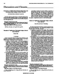
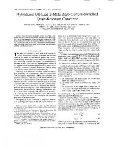
Thus, j u s t a s t h e s t a t i c i n v e r t e r has made p r a c t i c a lt h ed e v e l o p m e n to fv a r i a b l e speed i n d u c t i o n m o t o r d r i v e s , i t has p e r m i t t e d t h e d e v e l o p m e n t o f p r a c t i c a l , If the dc sup?ly to a voltage source inverter driving an induction machine is removed, self-excita- v a r i a b l e speed generators. Systems ot fh insa t u r e have been developed and patented by the Borg-Warner tion as aresult of circulating currents in the inverC o r p o r a t i o n( r e f e r e n c e1 ) . They o f f e r a l l o f t h e i n ter can occur whenever the inverter switching frequenas cy is below the machine speed. In this mode the inv- h e r e nat d v a n t a g e ostfh ei n d u c t i o nm a c h i n es, u c h r u g g e d n e s s ,h i g hs p e e do p e r a t i o n ,l a c k o f b r u s h e s ,e t c . erter-machine system functions astable as self-excited induction generator capable of supplying dcorac power The present paper covers the experimental and to a load. The electrical output of the system is t h e o r e t i c a ls t e a d ys t a t ea n a l y s i so ft h es e l f - e x c i t e d readily governed by slip control; thus the inverter mode o f o p e r a t i o n . makes practical the development of efficient induction generators capableof operating over wide speed ranges. SYSTEM DESCRIPTION A theoretical treatment based on a first harmonic As shown i n F i g . 1 t h eb a s i cs y s t e mc o n s i s t so f a approximation of inverter performance is presented. c o n v e n t i o n a ls i xp u l s et h r e ep h a s e V S I andan i n d u c t The results indicate that the magnetization characterion machine. istic and the stator and rotor resistances of the machine are the important parameters controlling sysForpurposes o fa n a l y s i st h es y s t e mi sv i e w e d as tem performance. Experimental results which confirm a c o n t r o l l a b l es o u r c eoef l e c t r i c a l power w i t ht h e the validity of the analysis and illustrate the behavas t h e dcbus v o l t a g e and c u r r ior of the self-excited systems are also presented. o u t p u t v a r i a b l e s t a k e n e n ot r a, l t e r n a t i v e l y a, st h em a c h i n ea cv o l t a g ea n d current. The s h a f te l e c t r i c a l speed ur i sc o n s i d e r e d INTRODUCTION as t h ei n p u vt a r i a b l e and t h ei n v e r t e fr r e q u e n c yo r machine s l i pi st r e a t e d as t h ec o n t r o vl a r i a b l e . The D u r i n gt h ec o u r s eo fs t a t i ci n v e r t e rd e v e l o p m e n t primaryfunctionoftheinverteristocontroltheexa t t h e Roy C. IngersollResearchCenter, an i n v e s t i g a c i t a t i o n o f t h e m a c h i n ew i t hc o n v e r s i o no ft h ea co u t t i o n wasmade o f t h e w e l l - k n o w n phenomenon i n whichan p u t o dc as a s e c o n d a rfyu n c t i o nB. e c a u s oet fh e i n d u c t i o nm a c h i n es u p p l i e df r o m a v o l t a g es o u r c e i n c r u c i a li m p o r t a n c eo ft h i se x c i t a t i o n supp:y f u n c t i o n , v e r t e r( V S I )c a no p e r a t ei nt h er e g e n e r a t i v e mode and a b r i , eqf u a l i t a t i v ed i s c u s s i o notfh e mechanism by supplypower t o t h e dcsourceconnected t ot h ei n v e r w h i c ht h ei n v e r t e ar c t s as a c o n t r o l l a b l es o u r c eo f ter. i t was f o u n dt h a t i f t h e dcsource i sr e p l a c e d r e a c t i v e power i s p r e s e n t ebde f o rper e s e n t i nt hg e w i t h a r e s i s t i v el o a dt h es y s t e mc a nc o n t i n u et os u p q u a n t i t a t i v ea n a l y s i s . p l y power t ot h el o a da t a voltagedeterminedbyan i n t e r n a le q u i l i b r i u mr e l a t i o n s h i pi n v o l v i n gt h ei n v e r terfrequency,machinespeedandthemachineparameters. The i n v e r t earc tass a c o n t r o l l a b l e means o f energycirculationforthereactive KVA o f t h e m a c h i n e andanyacload.
ABSTRACT
The e l e c t r i c a lo u t p u to ft h es y s t e m may be cont r o l l e db yc o n t r o l l i n gt h es l i p , hence t h eg e n e r a t o r i s made c a p a b l eoof p e r a t i n ge f f i c i e n t l yo v ewr i d e ranges o f s p e e d a n d l o a d b y p r o p e r c o n t r o l o f i n v e r t e r frequency. Dc v o l t a g ei so b t a i n a b l eatth ei n v e r t e r bus, and ac- voltage a t t h e i n v e r t e r f r e q u e n c y i s o b t a i n a b l ea tt h em a c h i n et e r m i n a l s .E x c e l l e n tv o l t a g ec o n t r o l may be a c h i e v e db yc o m p a r i n ge i t h e rt h e dc o r t h e ac o u t p u tv o l t a g e sw i t h a r e f e r e n c es i g n a lt od e r i v e an e r r o rs i g n a lw h i c ht h e nc o n t r o l st h ei n v e r t e rf r e quency. I n i t i a lb u i l d u p may beaccomplishedbysupplyi n g a s m a l l amount o f e n e r g y t o t h e dcbus o r byremn a n tf l u xi nt h em a c h i n e . F i g u r e1 .B a s i cV o l t a g eS o u r c eI n v e r t e r MachineSystem.
-
Induction
EXCITATION REQUIREMENTS This paper recommended and approved by the Kotating Machinery Com mittee of the IEEE Power Engineering society. This paper was presented at the 1975 Tenth A n n d Meeting of the IEEE IAS and was published in the IEEE Conference Record of the 1975 (75 CHO 999-3IA).
Each phase l a g g i n gc u r r e n t t hm e a g n e t i fci e l d
1117
o f ainn d u c t i om n a c h i nree q u i r e s a component r e l a t e dt ot h es t r e n g t ho f i n the machine. I n conventional
applicationstheseexcitingcurrentsaresupplied from the power system connected t o the stator terminals or, i n the case of self-excited a inductiongenerator, From thepoint ofviewof from a bank of capacitors. each phase winding, the magnetic fieldinthe machine i s an alternating field which requires a reactive power source f o r each phase. However,viewed as a whole, the a i r g a p f i e l di s of constantamplitude and once establishedrequiresnonetreactive power input. Thus i t i s f e a s i b l e t o simply arrangefortheproperinterchange of reactive power between the . phases of the need f o r a separate machine and hence eliminatethe energy storage system for each phase. The "reactive diodes" and theassociatedpathswithintheinverter provide a mechanism f o r t h i s phase - t o - phase energy transfer. motor the magniIn an inverterdriveninduction tude of the exciting current i s determined by the externallycontrolled dcbus voltage and the magnetizing characteristic of the machine. Iftheexternalcontrol of voltage i s removed and the machine speed raised above theinverterfrequency, mechanical energyisconverted t o electricalenergy, while theexcitingcurrent and terminalvoltageare determined by an internal equilibriumrelationship. As in any self-excitedsystem the magnetic nonlinearity of the machine i s an importantfactorinlimitingthebuildup of theexcitation. In theinvertercontrolled system the power and loss relationships and themagnetization characterpoint; i.e., i s t i c combine t o determinetheoperating a t no load theexcitationlossesareexactly balanced by the mechanical power converted. The determination and analysis of thisinternalequilibriumprocess is the main subject of t h i s paper.
The analysis problemof t h i s paper differsin a basic way from typical machine analysis problems i n t h a t no independent source of voltage of current exi s t s .I t shares some similarity i n thisrespect with a self-excited dc generator or a capacitor excited i n ductiongenerator.Thissimilaritysuggeststhe importat;ce of the nonlinearity of the magnetizing charact e r i s t i c b u t unfortunatelytheanalytical approaches used intheserelated problems do not carryover d i rectly because of the unique excitationsupplypropert i e s of theinverter. The model chosen to-represent thisproperty of theinverteriscentraltotheanalysis.
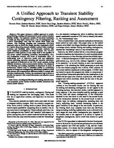
The inverter modelemployed i s based on theresu l t s of an analysis of inverterswitching modes presentedinreference 2. I n thisreference an inverter transfer characteristic which correctly represents the i n theinverteris devinternalcirculatingcurrents eloped. the Ifgeneral results are specialized to steady s t a t e and i f , inaddition, only the fundamental componentof the voltages and currents are represented, thegeneral model i s shown t o reduce t o theequivalent circuitin Fig. 2 . With t h i s approach theinverteris an ideal represented by an idealfrequencyconverter, transformer, and an adjustablereactive power source (a variablecapacitor). Within thelimits of theassumptionof negligible comnutation intervals the derivationinreference 2 of thisrepresentationis mathematicallyrigorous. The fol'lowing heuristic development i s only intended t o demonstratetheplausibility of the model.
Steady State Fundamental Component Equivalent Circuit of Voltage Source Inverter.
Neglectingthe comnutation interval, the phase neutral o u t p u t voltage of thebasic six pulse VSI Fig.1ithefamiliarstepped wave shown inthefigure. 2*396 Iftheinverteroutputvoltageis taken the fundamental componentof this wave, the phase neutralvoltage i s
to of
as to
w i t h correspondingfunctionsfor phases bandc.* Converting t o a two phase referenceusingtheconventional (power invariant)transformation,5theequivalent two phase inverter output voltages become
Iftheinverteris assumed lossless,the power be equal.Therefore, w i t h the input and o u t p u t must inverter input voltage and currenttaken as average dc quantities: VI 11 = vsu is,
+
vsg is*
(3)
For balanced operation w i t h a peaktwo phase current of I and a power factor angle, @, ( 3 ) becomes
THE ANALYTICAL MODEL
Representation of the Inverter
Figure 2.
+ sin at sin (ut =
fi V I TI
+
4)
I cos Q
Clearly ( 5 ) constrains only the i n phase component of theinverter o u t p u t current. T h e c i r c u i t of F i g . 2 representsthisconstraint by showing cancellation of the reactivecurrent by a variablecapacitor.Thefrequency conversion and the"transformerratio' of &in in F i g . 2 arealsoapparent i n ( 2 ) and ( 5 ) .
The representation o f the inverter by the equival e n t c i r c u i t of Fig. 2 isparticularly convenient f o r the analysis of self-excitationsince the capacitor i m d i a t e l y suggeststheequilibriumconstraintrelation. While the model appearsplausible on the basis of therelationshipsexpressedin ( 2 ) and (5), the detailed treatment of the inverter internal currents containedinreference 2 clearlyindicatesthe mechanism by which theexcitingcurrentscirculatewithinthe inverter . Machine Representation The machine model i st h e conventional two axis coupled c i r c u i t model w i t h transformation constants chosen t o yield power invariancy (Appendix A ) . Itis convenient t o use b o t h a stator reference and a synchronous reference i n theanalysis w i t h thestatorreferenceoccurring i n the form oftheconventionalequivalent circuit for steady state conditions.
Ispecificallyassociated with the *The factor ~ / I is three phase sixpulse VSI. Other inverters would have different"transformerratios" b u t theconcept of ( 1 ) would carry over.
1118
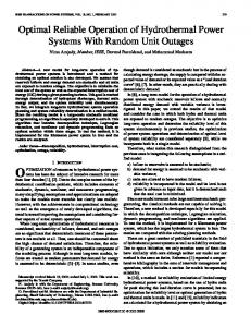
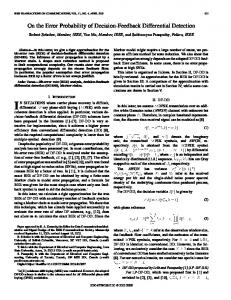
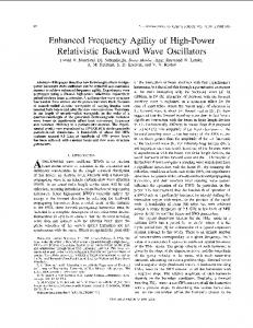
S i n c es a t u r a t i o no ft h em a i nm a g n e t i cc i r c u i ti s a criticalfactorintheanalysis,thevalueofthemagn e t i z i n gi n d u c t a n c e M i sc o n s i d e r e dt o be a v a r i a b l e dependinguponthe a i r gap f l u x andhenceupon the air gap v o l t a g e Vg and thefrequency w. F o rs t e a d ys t a t e M istakenastheslopeofaline a n a l y s i st h ev a l u eo f from t h eo r i g i nt ot h eo p e r a t i n g (V;g/w) p o i n to nt h e as shown n i magnetization characteristic ofthe machine F i g . 3. The leakageinductances L Q ~and L Q (see ~ Appe n d i x A ) a r et a k e n as c o n s t a n t s i n t h e a n a l y s i s as a r e t h er e s i s t a n c e sr 1 and '2.
Io
-
vs/w
NO LOADCURRENT
F i g u r e 3.
0 = [PI
i
where
1 i n e a r honogeneous e q u a t i o n s The 4 x 4 systemof r e p r e s e n t e d b y ( 1 1 ) K i l l have a s o l u t i o n i f and o n l y i f t h ed e t e m i n a n to f P i s zero. The r e s u l t o f t h i s mat r i xo p e r a t i o n w i l y i e l dt h e same b a s i cc o n s t r a i n t r e l a t i o n as t h ec o m p l e xv a r i a b l eo p e r a t i o ni n d i c a t e d i n (7).
-
M a g n e t i z a t i o nC h a r a c t e r i s t i c .
I
S t e a d yS t a t eE q u i l i b r i u mE q u a t i o n s
I
-
I
I
(a)
The e q u a t i o n sd e f i n i n gt h ee q u i l i b r i u ms t a t ec a n be o b t a i n e de i t h e rf r o me q u i v a l e n tc i r c u i tc o n s i d e r a t i o n so rt h r o u g h a m a t r i xf o r m u l a t i o n .S i n c e eachhas i t s advantages i n u n d e r s t a n d i n g a n d a n a l y z i n g t h e p r o b lem, bothapproachesarepresented. EquivalentCircuitRepresentation F o rs t e a d ys t a t eo p e r a t i o nt h e m o s ti m m e d i a t ec o n c e p t u a ls o l u t i o ni so b t a i n e db yc o n n e c t i n g t h e i n v e r t e r model o f F i g . 2 t o t h e s t a n d a r d s t a t o r r e f e r r e d e q u i v a l e n t c i r c u i t as shown i n F i g . 4 a .F o re i t h e r a three phase p e r phasemodel o r a twophasepower invariant t o the m o d e l ,t h ei n v e r t e rl o a dr e s i s t a n c et r a n s f e r r e d m o t o rt e r m i n a l s becomes
(&I F i g u r e 4.
E q u i v a l e n tC i r c u i tR e p r e s e n t a t i o n s , V S I C o n t r o l l e dI n d u c t i o nG e n e r a t o r .
The E q u i l i b r i u m E q u a t i o n f o r a s t a n d a r ds i xp u l s ei n v e r t e r . The reducedequivalent circuit of Fig. 4bthenyieldstheconstrdintfor steadystateequilibriumas
o f t h ei n p u at d m i t t a n c e where GI i s t h er e a lp a r t theinducrionmachineon a p e rp h a s eb a s i s .
Matrix
of
F o r a f i x e dr o t o rs p e e d and s l i p t h e c o n s t r a i n t be s a t i s f i e do n l yb yc o n s i d e r i n g o f ( 7 ) o (r 1 0 c) a n M t o be a v a r i a b l e . Thus, t h em a g n e t i z i n gi n d u c t a n c e forfixedrotor speed t h e r e e x i s t s a r e l a t i o n between M and s w h i c hi nc o n j u n c t i o nw i t ht h em a g n e t i z a t i o n 3 y i e l d st h ed e s i r e dr e l a t i o n between c u r v eo fF i g . voltageandslip. S e t t i n g d e t B = 0 yields the following quadratic M. equationforthemagnetizinginductance
Representation
T r a n s f o r m i n gt h ev o l t a g ea n dc u r r e n tc o n s t r a i n t s o f (2) and (5) t o a synchronousreference(AppendixA) yields
iS8
AM2+BM+C=0
(12)
where
rZ2 + r1r2s t (x1 t
A =
w2 [ s r 2 t s 2 r l t
unconstrained
c
The r e l a t i o n between VI and 11 canbeconverted t o a r e l a t i o nb e t w e e n us and is;
and t h es t e a d ys t a t em a t r i xe q u a t i o n r e f e r e n c e becomes
i n a synchronous
1119
r22x12 + s
= [ r 1 r zt2s 2 r 1 x Z 2 +
s2
1
R"
R"
~
~
1
~
~
X o t et h a t R\ c a nb ei n t e r p r e t e d as t h e r e f e r r e d v a l u eo ft h ei n v e r t e r bus l o a dr e s i s t a n c eo r as t h e phase t o n e u t r a l v a l u e o f a balancedresistiveloadon the machine terminals. W h i l e( 1 2 ) i s t h e d e s i r e d s t e a d y s t a t e c o n s t r a i n t r e l a t i o n i t i s somewhat c o m p l i c a t e d i n i t s complete f o r ma n da n a l y s i sa n di n t e r p r e t a t i o na r eb e s t made i n terms o fs p e c i a lc a s e so rw e l lc h o s e na p p r o x i m a t i o n s . I f c o m p u t e rs o l u t i o n sa r ea c c e p t a b l e ,t h ef u l le q u a t i o n canbeused. O p e r a t i o n a t No Load
(12) Underno l o a dc o n d i t i o n st h ec o m p l e x i t yo f i sc o n s i d e r a b l yr e d u c e da n d a n u m b e r o f u s e f u lr e s u l t s canbeobtained. The b a s i co p e r a t i n gc h a r a c t e r i s t i c s o ft h e systemcanbereadilyunderstoodfromthese s i m p l i f i e dr e s u l t sa n dt h ee f f e c to ft h el o a d added subsequently as a m o d i f i c a t i o n o f t h e n o l o a d p e r f o r mance.
S
The q u a d r a t i cd e s c r i b i n gn ol o a dp e r f o r m a n c ei s R" approach i n f i n i t y . o b t a i n e df r o m( 1 2 b) yl e t t i n g The r e s u l t i n ge q u a t i o ni ss u f f i c i e n t l ys i m p l et oe x p r e s st h e" e x a c t "s o l u t i o n as
F i g u r e 5.
RESULTANT AIR GAP VOLTAGE
D e t e r m i n a t i o no f Air Gap V o l t a g e U n d e rI n v e r t e rS e l f - E x c i t a t i o n .
Operation at Small
S1 i p
F o rs m a l vl a l u e so fs l i p a v e r ys i m p l er e l a t i o n (13) b yn e g l e c t i n g between M and s i so b t a i n e df r o m terms i n s 2 S e v e r a lp r o p e r t i e so ft h es y s t e ma r ei m e d i a t e l y apparent from i n s p e c t i o n o f (13): T h i sr e s u lct l e a r l yd e m o n s t r a t e st h ei m p o r t a n c e o f t h e machineresistances i n e s t a b l i s h i n g t h e M vs. s c h a r a c t e r i s t i c . It i s u s e f u l t o c o n s i d e r t h e r e s u l t o f ( 1 5 )f r o mt h ep o i n to fv i e wo ft h ee q u i v a l e n tc i r c u i t o f F i g . 4b.The reduced c i r c u i t f o r s m a l l s l i p andno l o a d i s shown i n F i g . 6 a l o n g w i t h t h e a p p l i c a b l e phasordiagram.Since s i ss m a l l I z i ss m a l l compared t o Im and
t h e r e i s a t m o s t one r e a l v a l u e d positive solution for M a t a g i v e n s l i p andfrequency; there is a limited rangeof slip o v e rw h i c hs o l u t i o n se x i s t , bounded by t h e s o l u t i o n s o f s'rl
+ sr, = 0
whichare
The e q u i l i b r i u mr e l a t i o nf o rs m a l l s ( 1 5 ) i s obt a i n e db ye q u a t i n gt h e( n e g a t i v e ) power i n r,/s t o t h e s t a t o r loss
s = 0, s = -r,/rl and t h e v a l u e o f M approaches i n f i n i t y a t thesetwovaluesofslip andhence a m i n i m u m e x i s t s somewhere between t h e s e boundary values
W i t ht h i si n t e r p r e t a t i o ne q u i l i b r i u mi sa t t a i n e d when t h es t a t o r losses-,whichincrease as s a t u r a t i o n i n c r e a s e s a, r ej u s st u f f i c i e n t ob a l a n c et h e power convertedfrommechanicalform. Thus, an i n c r e a s ei n s l i p r e s u l t s i n moreconverted power a n d a n i n c r e a s e i n saturation. From t h i sp o i n to fv i e w i t i sc l e a rt h a t a d d i t i o n a ls t a t o rc i r c u i tl o s s e s( i n v e r t e rl o s s e s )c a n r; whereas core and eddy b ce o n s i d e r e tdion c r e a s e c u r r e nlto s s e sc a nb e added i np a r a l l e lt or z / s and e f f e c t i v e l yi n c r e a s et h ev a l u eo f r 2 ( s i n c e s i s negative). Thus t haed d i t i o n allo, s s ei sn a practical systemcan be i n c o r p o r a t e db yi n c r e a s i n gt h ev a l u e so f rl and r 2 a l t h o u g ht h en o n - o h m i cn a t u r e o f t h ei n v e r t e r an3 corelossescancauseanomalousbehavior.
.
These p r o p e r t i e sa r es u f f i c i e nttop r o v i d e an understanding of the interactions involved in the selfe x c i t a t i o np r o c e s s . The e q u i l i b r i u mc o n s t r a i n tr e l a M and s shown t i o n( 1 3 )d e t e r m i n e st h ec u r v er e l a t i n g s a tt h el e f ti nF i g . 5. For a p a r t i c u l a rv a l u eo f t h e c o r r e s p o n d i n g M d e t e r m i n e s t h e a i r gap f l u x o n t h e m a g n e t i z a t i o nc u r v e as i l l u s t r a t e d i n t h e u p p e r r i g h t o fF i g . 5. The e n t i r e a i r g a pv o l t a g ev s .s l i pc h a r a c t e r i s t i ci s th::s determined and would appear as shown i n t h e l o w e r r i g h t on t h i s f i g u r e . Clearlyself-excitedoperationofthemachineis s t r o n g l y d e p e n d e n t o n t h e shapeand s c a l e o f t h e M vs. s c h a r a c t e r i s t i dc e f i n e bd y (13). B e f o re x p l o r i n g t h ef a c t o r sw h i c hi n f l u e n c et h i sc h a r a c t e r i s t i c , i t i s h e l p f u lt oc o n s i d e r a r e s t r i c t e dc a s ew h i c ha l l o w s a s i m p l ep h y s i c ai ln t e r p r e t a t i o notfh e mechanism o f self-excitation.
The Complete M vs. s C h a r a c t e r i s t i c C o n s i d e r a b l ei n s i g h ti n t ot h ef o r mo ft h e M vs. s characteristic an b eo b t a i n e db yl o c a t i n gt h es l i p of t h e minimum M. This f o r minimum M and t h ev a l u e
1120
Minima s l i p for s e l f - c i t a t i o n
Since the a i r gap inductance 4 o f a machine i s t h em a x i ma t t a i n a b l e magnetizing inductance, the smallest s l i p which w i l y i e l d a s o l u t i o n i s t h e value corresponding to t h i sm a x i m inductance. From (15) the approximate value o f t h i s minirequired slip is rlr2
so=--
(20)
(w
LIaximm s l i p and voltage
Figure 6.
EquivalentCircuit and Phasor Diagraa for No Loadand W a l l S l i p .
The p o r t i o no ft h e tf vs. s c h a r a c t e r i s t i cf o r mre negativethan%in i s normally values o fs l i p s t a t i c a l l y u n s t a b l e j u s t as f o r s l i p values beyond the toque M n m x i f o r n o t o r operation. The most negative attainable slip is therefore norrrally
can be acconplished w i t h acceptable accuracy byneglectingthefirsttennunderthe square root i n (13). The result is
where the choice o f Z i s determined bywhether w o r wr i s constant i n the particular application. i f theminimization
is carried out for constant rotor Fora given stator frequency the maximum a t t a i n ablevoltage corresponds t o t h e m i n i m value of U. A convenient approximate expression f o r t h i s value o f U i s obtained from (19) by neglecting the rotor leakage inductance :
speed and
9.. L I
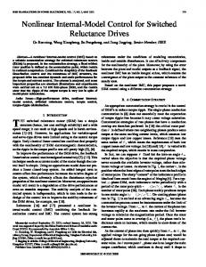
\.i n = 2 . w i f the minimization i s c a r r i e d out for constant stator frequency. The actual values o f s l i p a r e s l i g h t l y l e s s negative and themininunvalues slightly smaller than thevaluesgiven i n (18) and (19) because o f the approximation used. The nature o f t h e H Y S . s character-' i s t i c s f o r c o n s t a n t r o t o r speed a r e i l l u s t r a t e d i n Fig. 7 where the difference between thecharacteristics with and without rotor leakage inductance are exaggerated t o show t h e e f f e c t o f t h i s parameter.
This result shows the importanceof r l i n l i m i t i n g the maxinun voltage and also indicates that an increase i n frequency notonly causes the n o m 1 proportional increase i n voltagebut i s also accolnpanied by an i n crease i n thepermissible degree ofsaturation. Thus the maximum attainable voltage increases more than l i n e a r l y w i t h frequency. Minimum speed and frequency
The e f f e c t o f an increase i n r o t o r speed i s i n d i cated on the figures. In generalhigher speed ( o r f r e quency) reduces thevalue o f h j n andmakes thevalue of %in less negative.
If the rotorspeed o r frequency i s veryo w l the mininun value o f t h e U vs. s characteristic w i l r i s e above the a i r gap inductance and self-excitation w i l not occur. Neglecting rotor leakage inductance(18) y i e l d s
as t h el i m i t i n g value i f speed i s independently cont r o l e d , and (19) y i e l d s
1'rn
i l t i i f inverter frequency i s f o rt h e corresponding m independentlycontrolled. I np r a c t i c e one should expect results considerably higher than these values because of the additional losses i n the system.
0
Figure 7.
Operation UnderLoad
M vs. s Characteristic a t Constant Rotor Speed.
Limits of Self-Excitation at
No Load
A number o fl i m i t a t i o n s on the range o fs e l f excitation can be deduced from'the nature o f the U vs. s cbrocteristics. Simple approximate expressions l i m i t on s i g n i f i c a n t showing the dependence ofthe machine parameters arealsoobtainable but the more exact expressions should be used i f mre accurate bounds are required.
When operating with a load the quantity R" i n (12) i s f i n i t e and t h ef u l lf o n no f (12) must beused i n place ofthesimplifiedfonnleading to (13). To obt a i n an approximate solution which w i l devnrstrate the effects of load resistance, only the dminant new t e r n areretained.Withthisapproximation,thebasicfonn of the quadratic equation i s not altered and a solution s i m i l a r t o the no load case i s possible. The approximate f o m o f (12)obtained by t h i s approach has the coefficients
1121
A = w2[sr2 + s 2 r 1
+
rZ2/R"]
B = 2w [ s 2 r 1 x 2 t r,2~,/R"] C = r 1 r 2 2 +s 2 r 1 x Z 2 from khich the solution for
M canbeexpressedas
s2r1 + sr2 t
R" The b a s i pc r o p e r t i e lsi s t e fdo(r1 3a) r ae l s o valid for this result except that the rangeof slip for w h i c h s o l u t i o n s e x i s t i s m o d i f i e d t o t h e r e g i o n between thesolutionsof s2r1
+
sr,
+ rZ2/R" = 0
I
I
-r2
-r2
r1
F i g u r e 8.
O p e r a t i o na tS m a l lS l i p
s + r,/R"
( 2 6 ) reduces t o
-
r1
lo 0
E f f e c t o f LoadResistanceon CharacteristicatConstant
M wr.
E
The o u t p u t v o l t a g e d i f f e r s fromthe a i r gap v o l t If t h e age because o tf h es t a t o rl e a k a g e impedance. rotorleakageimpedanceisneglectedasimpleexpression fortheratiooftheterminal and a i r gap voltagescan beobtainedfromthephascirdiagramofthemachine. The e q u i v a l e n t c i r c u i t andphasordiagram(withx2=0) a r e shown i n F i g . 9. S i n c et h e components o f I1 are I m and Iz, t h et e r m i n a lv o l t a g ec a n be w r i t t e n as
The s l i p r a n g e f o r w h i c h s o l u t i o n s e x i s t i s t h e r e f o r es m a l l e sr i n c e each boundary i s moved inwardby r,/R" compared t o t h e n o l o a d c a s e .
r,LL1/R"
3
R"
r)utp
(27)
M = -
s-
-+p t7
w h i c ha r e( a p p r o x i m a t e l y )
F o rs m a l lv a l u e so fs l i p
I
rz
1"z
u2 (s + r,/R")
f r o mw h i c ht h er a t i oo fv o l t a g e sc a nb eo b t a i n e da s
By c o m p a r i s o n w i t h ( 1 5 ) f o r n o l o a d o p e r a t i o n t h e M vs. s c h a r a c t e r i s t i cf o rs m a l ls l i pi ss h i f t e dt o m o r en e g a t i v es l i pb ya n amount r,/R" and s h i f t e d upwardbyan amount p r o p o r t i o n a tl or , L & l / R " . The n e t effectistoincrease M foraparticular valueofslip. Thiscauses a r e d u c t i o n i n t h e a i r gap v o l t a g ew h i c h i si na d d i t i o nt ot h el e a k a g e impedancedropcaused b yt h el o a dc u r r e n t .
b yu s i n gt h ee x p r e s s i o n s
The minimum s l i p r e q u i r e d t o s u s t a i n s e l f - e x c i t a t i o n becomes
T h i sr e s u l t shows t h a t h et e r m i n a vl o l t a g ee x ceeds t h e a i r gap v o l t a g e when s i s s m a l l( i . e . ,a t no l o a d ) as i s t o beexpectedsincethemachine i s operat i n g i n t o a c a p a c i t i v el o a d . As t h el o a di s addedand s becomes m o r en e g a t i v e ,t h et e r m i n a lv o l t a g e may bec o m e . l e s st h a nt h ea i rg a pv o l t a g e .
whichbycomparisonwith (20) f o rn ol o a do p e r a t i o n r,/R". These r e shows a ni n c r e a s ep r o p o r t i o n atlo s u l t s c l e a r l y show t h e i m p o r t a n c e o f r , i n c o n t r o l l i n g M t h ed e g r e et ow h i c ht h ee x t e r n a l o a da f f e c t st h e vs. s c h a r a c t e r i s t i c andhence t h el e v e lo fs a t u r a t ion. The Complete M vs. s C h a r a c t e r i s t i c The c o m p l e x i t y o f ( 2 6 ) p r e c l u d e s a s i m p l ec l o s e d f o r m d e t e r m i n a t i o n of smin and b i n f o r o p e r a t i o n w i t h show t h a t Smin beload. However i t i sp o s s i b l et o comes morenegativeand h j n l a r g e r as R" decreases. These t r e n d sa r ei l l u s t r a t e di nF i g . 8. The a d d i t i o n of load to the machine therefore generally reduces the s a t u r a t i o n l e v e l and o u t p u t v o l t a g e f o r a g i v e nv a l u e o fs l i p . Note, however, t h a lt a r g e rv a l u e so sf l i p a r ep o s s i b l eu n d e rl o a dt h a na tn ol o a d .
1122
F i g u r e 9.
E q u i v a l e n tC i r c u i ta n dP h a s o rD i a g r a m , S e l f - E x c i t e d V S I I n d u c t i o n Machine.
ExperimentalResults
ParameterMeasurements
Testsrunon a s m a liln d u c t i o ng e n e r a t o sr y s t e m c o n f i r mt h eb a s i cv a l i d i t yo tf h et h e o r yp r e s e n t e d . A1 t h o u g h t h e c a l c u l a t e d a n d e x p e r i m e n t a l r e s u l t s d o n o t a g r e eq u a n t i t a t i v e l yu s i n ga c t u a l measuredmachineres i s t a n c e st h eb a s i cc h a r a c t e r i s t i c sa r ea l lc o r r e c t l y p r e d i c t e d .U t i l i z i n gi n c r e a s e dv a l u e so f r 1 and r 2 t o m i a c c o u nfto irn v e r t e r and machine losses greatly p r o v e st h eq u a n t i t a t i v ea g r e e m e n t . System D e s c r i p t i o n The e x p e r i m e n t a ls y s t e mc o n s i s t so f a one horsepower i n d u c t i o n m o t o r u s e d a s t h e g e n e r a t o r d r i v e n b y a f i v e h o r s e p o w e rs y n c h r o n o u sr e l u c t a n c em o t o r t o p r o v i d e an i n d e p e n d e n t l cy o n t r o l l e dr o t o r speed source. The d r i v em o t o rc a nb ep o w e r e de i t h e rb yt h es i x t yh e r t z l i n e o r by a v a r i a b l e f r e q u e n c y i n v e r t e r .
GeneratorparametersweremeasuredbyusingstanA z e r o s l i p t e s t was p e r d a r di n d u c t i o nm o t o rt e s t s . formed with the synchronous motor driving the induction machine a t synchronous speed. This t e s yt i e l d e dt h e magnetizinginductance. A b l o c k e d r o t o r t e s t was u s e d t o d e t e r m i n e l e a k a y e i n d u c t a n c e sa n dt h es t a t o rr e s i s t a n c e w a s m e a s u r e dw i t h a d cb r i d g ea f t e rt h em a c h i n e was warm. R o t o rr e s i s t ance was c h o s e n b y m e a s u r i n g t h e v o l t a g e , c u r r e n t , s l i p a n dt o r q u eo tf h em a c h i n eo p e r a t e d as a motorunder l o a d and c a l c u l a t i n gt h ev a l u eorfo t orre s i s t a n c e which, i nc o n j u n c t i o nw i t ht h eo t h e rp a r a m e t e r s , gave t h ec o r r e c ot p e r a t i n gp o i n t A . ppendix B c o n t a i n st h e inductionmachinedata. The m a g n e t i z a t i o nc h a r a c t e r i s t i ci si n c l u d e di nF i g .1 1 . ExperimentalPerformance
A t h r e e phase b r i d g e i n v e r t e r u s i n g s i l i c o n c o n t r o l l e d r e c t i f i e r s asswitchingelementsprovidesgener a t o re x c i t a t i o n .I t sd i r e c tc u r r e n t bus i s connected across a f o r t y m i c r o f a r a d c a p a c i t o r i n o r d e r t o smooth t h e dvco l t a g eT.h i s i s done t po r o v i d e an e a s i l y measured q u a n t i t yf o rc o m p a r i s o nw i t hc a l c u l a t e dd a t a and f o r c o n t r o l o f t h e system. The i n v e r t e gr a t i n gs i g n a l sa r ed e r i v e df r o m a v o l t a g ec o n t r o l l e do s c i l l a t o r whose i n p u ti sp r o p o r t i o n a lt ot h ed i f f e r e n c e bteween a r e f e r e n c ev o l t a g e and t h ei n v e r t e r dcvoltage. Thus a negativefeedback system i s c r e a t e d w h i c h a l l o w s t h e s e t t i n g o f anydesi r e ds t e a d ys t a t eo p e r a t i n gp o i n t .F o r measurements o f t h ee x t r e m el i m i t so fo p e r a t i o n ,t h ef e e d b a c kc o n t r o l may be d i s c o n n e c t e da n dt h ei n v e r t e fr r e q u e n c yc o n t r o l l e d as an i n d e p e n d e n tq u a n t i t y . A b l o c kd i a g r a mo f theexperimentalsystem i s shown i n F i g .1 0 . As p r e v i o u s l ys t a t e d ,t h ed cv o l t a g ei st a k e nt o be t h er e f e r e n c ef o r measurement.Therefore allvoltages a r e t r a n s f o r m e d b y t h e f a c t o r 2/n i n t o a d c e q u i v a l e n t .S l i pi s measuredusing a d i g i t a lc o u n t e rc o n n e c t e dt ot h ev o l t a g ec o n t r o l l e do s c i l l a t o r . The r o t o r speed i s assumed t o be 377 r a d i a n s / s e c when thesynchronousmotor i s c o n n e c t e d t o t h e l i n e ; o r e l s e e q u a l t o t h ed r i v ei n v e r t e fr r e q u e n c yw h i c hi sa l s o measured w i t h a d i g i t a lc o u n t e r .
The g e n e r a t o r i s s t a r t e d b y s w i t c h i n g a d c v o l t a g e s0urc.e a c r o s st h ee x c i t i n gi n v e r t e rd c bus. The inve r t e rf r e q u e n c yi ss l o w l yl o w e r e do rt h er o t o r speed r a i s e du n t i tl h e bus v o l t a g e exceeds t h ea p p l i e d dc voltage. A t t h i sp o i n ts e l f - e x c i t a t i o nh a s been achievedandthedcsource i s removed.
20v
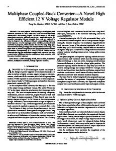
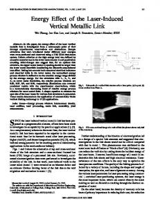
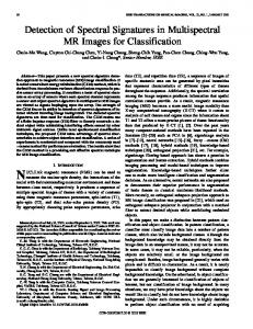
Measurement o f s t e a d ys t a t ec h a r a c t e r i s t i c si n v o l v e st h es e l e c t i o no f a no p e r a t i n gv o l t a g e and measurement o fs l i p . The measurements a r er e p e a t a b l et o w i t h i n a fewpercentaslongasthegeneratortemperat u r ei sm a i n t a i n e dc o n s t a n t . Measurements o ft h ee x treme limits of operation are best made w i t h t h e f e e d backremoved, s i n c et h eg e n e r a t o rs u d d e n l yl o s e se x c i t a t i o n a t i t s limit. Measurement o f s l i p mustbetaken a f t e rt h a t happens.Thesemeasurementswerealsofound t o be r e p e a t a b l e a l t h o u g h a n e x a c t d e t e r m i n a t i o n o f t h e limit r e q u i r e ss e v e r a la t t e m p t s . Voltage Versus S.l ip Measurement o f s l i p anddcvoltage atvariousope r a t i n gp o i n t sy i e l d st h ev o l t a g ev e r s u ss l i pc h a r a c t e r i s t i c . Two such curves are shown i nF i g . 11. The f i r s t i s f o r no loadoperation,andthesecond isfor a s i x t y ohm loadconnectedacrosstheinverterdcbus. N o t i c et h a t h e noloadcurve shows d e c r e a s i n gs l i p withincreasingvoltageatvoltageswhicharelessthan t h es a t u r a t i o nv o l t a g e .T h i si s an i n d i c a t i o n t h a t t h e l o w e rm a g n e t i z i n gi n d u c t a n c ea tl o wf l u xl e v e l s has a s i g n i f i c a n te f f e c t on t h eo u t p u tc h a r a c t e r i s t i c . The i n v e r t e rs e m i c o n d u c t o rv o l t a g ed r o p s ,w h i c hr e p r e s e n t a h i g h e rp e r c e n t a g eo fl o s sa tl o wv o l t a g e s , may a l s o p l a y a more s i g n i f i c a n t r o l e a t t h e s e l o w v o l t a g e s . Saturationeffectsareevidentatthehighervolbecomes i n c tages as t h e change i n v o l t a g e w i t h s l i p r e a s i n g l ys m a l l e r F. i g . 11 shows thesecurvescompared w i t ha n a l y t i c a lc u r v e sd e r i v e d from (121, a c c o r d i n gt o t h em e t h o do fF i g . 5. The g e n e r a ls h a p eo ft h ec u r v e s areallthe same, b u t t h e b u i l d u p s l i p andthe minimum m a g n e t i z i n gi n d u c t a n c eo ft h ea n a l y t i cc u r v e sa r e much s m a l l e r . However, t h ea n a l y t i cc u r v e st o o kn oa c c o u n t o fi n v e r t e r o r c o r el o s s e s . As shown i n F i g . 11 b yt h e m o d i f i e da n a l y t i cc u r v e s ,d o u b l i n g t h e s t a t o r and r o t o r r e s i s t a n c e st o m o d e li n v e r t e r ,c o r e ,a n dh a r m o n i cr o t o r l o s s e sb r i n g st h es t e a d ys t a t ea n a l y t i cs o l u t i o n much c l o s e rt ot h ee x p e r i m e n t a lc u r v e s . b i n andsmin
V I
Figure 10. Experimental Generating System.
120 v
The minimum m a g n e t i z i n g i n d u c t a n c e a n d t h e c o r r e sponding s l i p a r e measured a t a l o w e rr o t o r speed t o r e d u c et h es t r a i no nt h ei n v e r t e rV. o l t a g ef e e d b a c k i s removed and s l i pi si n c r e a s e du n t i tl h eg e n e r a t o r s u d d e n l yl o s e se x c i t a t i o n . The s l i p a t t h a t p o i n t i s t a k e n t o besmin,and t h e maximum v o l t a g e a t t a i n e d r e corded.This maximum v o l t a g ei sa s s u m e d t o b ee q u a lt o t h e a i r gap v o l t a g ew h i c ha l l o w s b i n t o be o b t a i n e d from t h e m a g n e t i z a t i o n c u r v e .
1123
Figure 1 1 .
Comparison of Experimental and Calculated Voltage Vs. Slip Curves.
These quantities are shown in Table 1 compared with the analytically predicted values. Smin compares very well, but b i n is much larger than predicted. This disagreement may again be reconciled by assuming that the stator and rotor resistances are larger by a factor o f two as shown in the last column o f Table 1. I
I
I
I
I
I
Minimum Slip for Steady State Operation Minimum slip for steady state operation, so, is found by an open 1 m p increase o f inverter frequency at constant speeduntil the generator lose sexcitation. As already pointed out several other nonlinearities affect the operating point and inverter losses become more significant at low voltages. Therefore it is not unexpected that So is considerably greater than predicted. The comparison is made in Table 1. Minimum Rotor Speed The minimum rotorspeed may be measure:i by slowly reducing rotor speed while maintaining a low output voltage on the generator. At times thegeneratcrwould lose excitation but could be restarted. Rotor speed was recorded when the generator couldno longer be restarted. Table 1 shows that the minimum rotorspeed is much larger than predicted. But a calculation with doubled rotor and stator resistances showsan improved canparison with the measured value as expected.
= 126 *rad/sec no load VocruJI=198V
I
1
I
%in slip corresponding to %in minim rotor Speed
Sumnary The theoretical and experimental re..i:lts presented in this paper illustrated the self-excitation proper-
I
' D c 2ov
77 rad/ SeC
39.4 rad/ SeC
87.7
43.8
ties of a voltage source inverter supplying an induction machine. The validity of the equivalent circuit
1124
r e p r e s e n t a t i o no ft h ei n v e r t e r( F i g .2 ) and t h e a b i l i t y t op r e d i c t h ei m p o r t a n pt r o p e r t i e s and l i m i t a tionsofself-excitationby means o f a f i r s t harmonic approximationhave beendemonstrated.Whilethe magnetizationnonlinearityofthemachine hasbeen shown t o be t h e key f a c t o r i n t h e p r o c e s s o f s e l f - e x c i t a t i o n , i n v e r t e r andmachinelossesareimportantsecondary factors. I f a!lowance i s made f ot rh e sleo s s ebsy i n c r e a s i n gt h ev a l u e so ft h em a c h i n er e s i s t a n c e s ,t h e expressionsdevelc3ed i nt h e p a p e ry i e l da c c e p t a b l e predictionsoftheoutputcharacteristics and l i m i t a tionsofself-excitedoperation.
Subscripts 9 a i r gap q u a n t i t y I i n v ei rnqt peuuratn t i t y min minimum v a l u e s t, ar t or or ,tqoura n t i t y t t e r mqi un a nl t i t y a,B phases o f two phase machine 'd,6 phases o f synchronous machine 1,2 e q u i v a l ecni rt c uq iut a n t i t i e s
APPENDIX A Power I n v a r i a n tC o u p l e dC i r c u i tE q u a t i o n s l S y n c h r o n o u sR e f e r e n c e
T=nM[ir
iS6 ir s -is ]
cos
ut
-sin
ut
Onerations -~
cos
p bh aqrsu oa rn t i t y [ 3 matrix P dtei m r i ve a t i v e wt
APPENDIX B
References
InductionMachineNameplateData: Frame Type HP RPM FREQ VOLTS AMP
01220
D56 FS 1 .o 1725 50160 11 613
G . H. Studtmann, AC-DC G e m r a t i n gS y s t m , P a t e n t No. 3,829,758; August 13, 1974, assigned t o t h e Borg-WarnerCorporation.
2.
0. W. Novotny,"SwitchingFunctionRepresentation o f P o l y p h a s eI n v e r t o r s , "s u b m i t t e dt o IEEE-PAS.
3.
J. M. D. Murphy, T h y r i s t o rC o n t r o ol f
P. C . Krause, T. A. L i p o ," A n a l y s i sa n d S i m p l i f i s 2 R e p r e s e n t a t i o no f a R e c t i f i e r - I n v e r t e rI n d u c t i o n IEEE-PAS, Vol. 88, No. 5, 1969. MotorDrive,"
5.
C . V . Jones, The U n i f i e Td h e o royEf l c c t r i c a l Machines,Butterworth & Company, 1967.
.85 R 11 Fig.see .56 R
ACKNOWLEDGEMENT
Symbo 1 s
S
V
V X Ll Wr
6
Yotors_,
4.
Notation:
i I LL M I: r
AC
U. S .
Pergamon Press Co.,1973.
InductionMachineParameters: rl S t a t o rR e s i s t a n c e hy .0022LL1 S t a t o r Leakage M MagnetizingInductance hy .0022Le2 RotorLeakage r 2 RotorResistance
1.
t vi m a reyci un rgr e n t dc o r peak c u r r e n t leakageinductance m a g n e itni zdi un cgt a n c e r e s is t a n c e m a rcehsi ni set a n c e slip tvi na er yvi no gl t a g e dc o r peak voltage machine reactance r fardeiqaune n c y r o t o r speed phaseangle
The a u t h o r s w i s h t o e x p r e s s t h e i r a p p r e c i a t i o n t o t h eU n i v e r s i t yo fT e c h n o l o g y ,E i n d h o v e n ,N e t h e r l a n d s , o f t h i sp a p e r . fortheirsupportduringthewriting
1125