Shock and Vibration 15 (2008) 619–629 IOS Press
619
Lessons learned in applying accelerometers to nuclear effects testing Patrick L. Walter PCB Piezotronics, Inc. and Texas Christian University, Box 298640, Fort Worth, TX 76129, USA Tel.: +1 817 257 6318; E-mail:
[email protected] Received 25 May 2004 Revised 13 April 2007
Abstract. Exoatmospheric nuclear effects, such as those that would be encounter by reentry bodies, provide instantaneous (near zero-duration), impulsive loading of structures. Endoatmospheric nuclear effects possess an impulse that is finite in duration, but whose rise time is still instantaneous. The commonality of these loadings is that they initiate waves propagating through structures, resulting in extremely short duration accelerations to free surfaces where accelerometers are mounted. Over the years, attempts have been made to measure free surface accelerations using ceramic, quartz, and piezoresistive accelerometers. This paper describes the lessons learned, and looks to the future. It also provides a history of shock accelerometer development.
1. Introduction During the Cold War, testing techniques evolved to simulate the loading effects of nuclear detonations on structures. Simulation techniques included pulsed electron beams, magnetically or explosively driven flyer plates, light initiated explosives, and explosively driven shock tubes. Testing was performed to reduce weapons vulnerability and allow hardening against countermeasure effects. To understand the effects of nuclear detonations, it is necessary to consider the categories of energy in a nuclear detonation. They consist of: – the kinetic energy of electrons, atoms, and molecules, – the internal energy of these same particles, and – the thermal radiation energy (this energy category is not significant in conventional chemical explosions because the temperatures involved are lower by four orders of magnitude). The fraction of the nuclear explosion yield received as thermal energy at some distance from the burst point depends to some extent on the nature of the weapon, but it primarily depends on the environment of the explosion. A typical energy distribution for an airburst of a fission weapon at an altitude below 100,000 feet is [1]: – – – –
Blast and shock 50%. Thermal radiation 35%. Residual nuclear radiation from fission products which emit gamma and beta particles 10%. Initial nuclear radiation consisting primarily of gamma rays 5%.
At higher altitudes, a greater percentage of the energy appears as thermal radiation and a lesser percentage as blast and shock due to the less dense atmosphere. Because of the high temperatures associated with nuclear explosions, 60 to 70 percent of this total radiation may be in the form of x-rays. In a lower altitude detonation, the atmosphere absorbs the low energy portion of these x-rays by conversion into kinetic and internal energy of the oxygen and nitrogen molecules. ISSN 1070-9622/08/$17.00 2008 – IOS Press and the authors. All rights reserved
620
P.L. Walter / Lessons learned in applying accelerometers to nuclear effects testing
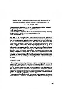
Fig. 1. Plane wave propagating through material.
During exoatmospheric flight of a reentry vehicle near a nuclear detonation, impulsive loadings would be experienced by the reentry vehicle due to the lower energy X-rays being absorbed by the heat shield. This X-ray energy causes instantaneous heating of the surface material, resulting in very rapid spalling and vaporization of an outside layer. The rapid material “blow-off” results in an impulsive force being imparted to the vehicle structure. Flyer plates are typically employed to simulate this circumstance in experiments. Vulnerability testing of the reentry vehicle through simulation attempts to answer the question of how much load a vehicle can take and still remain functional. Generally, impulses supplied to the vehicle are less than a few thousand taps (1 tap = dyne-sec/cm 2). Transient loads imparted to the vehicle may be in the tens of kilobars region. After vulnerability testing is complete, static load deflection tests, vibration resonance surveys, or an actual vehicle flight may be performed to verify that functional integrity and reliability have been maintained. Lethality testing is an attempt to simulate reentry vehicle failure criteria. The test objective is to determine how much load a vehicle can withstand before it is no longer functional. Impulse levels imposed may be tens of thousands of taps. Within the atmosphere, the mechanical effects of a nuclear detonation consist primarily of blast waves transmitted through the air. Explosively driven shock tubes simulate this air blast event. In the shock tubes, not only is the air blast environment simulated but an attempt is made to duplicate the actual pressure-time profile.
2. Mechanical response considerations In any of the previous described loading situations where forces are applied for very short periods or are rapidly changing, it is convenient to consider two different types of system response and analysis. The initial response of a structurally complex system to this loading will be defined as its material response. This is the response that lasts until dilatational waves propagating in the structure have essentially dissipated. Dependent upon the magnitude and rate of dynamic loading, as well as the types of materials that compromise the structure, these waves can be elastic, viscoelastic, plastic, or shock [2]. Shock waves result from the property of most materials to transmit sound at a speed that increases with pressure beyond an initial elastic region. The system response that occurs once wave propagation is no longer a consideration will be defined as structural response. Depending on the structure, structural response can persist for one, tens, or hundreds of milliseconds. It can last even longer for large systems. Dynamic analysis of a complex system to predict structural response treats it as an assemblage of a finite number of elements connected at a discrete number of nodes. The complete dynamics problem is defined only when both responses are considered. A simple example will illustrate this distinction. Detonating high explosives in contact with an inert material can produce shocks in the material. The use of flyer plates is a technique that achieves much higher pressures than are achievable by direct methods. Figure 1 shows a plate where only dilatational waves are propagating in its center. This implies a condition of uniaxial strain. Uniaxial strain can be achieved in the central region of large, flat plates for times shorter than the time required for a relief wave to propagate from the edge of the plate into the central region. High explosives liberate energy in the form of heat when they detonate. When this happens, the gaseous products are raised to very high temperatures and, as long as they remain confined, very high pressures. A detonation wave passing through the high explosive initiates the chemical reaction, and the pressure produced continues to feed
P.L. Walter / Lessons learned in applying accelerometers to nuclear effects testing
621
Fig. 2. Pressure versus particle velocity for aluminum flyer plate explosively loaded by TNT.
the shock so that it does not attenuate as it passes through the high explosive. At the instant a detonation wave has completely burned all the explosive, all the products are at the Chapman-Jouget (C-J) point [3]; that is, after detonation the products of the burned explosive are at a known pressure, density, and particle velocity. Figure 2 illustrates the left going curve for the explosion products of TNT. In this case, the TNT loads a flyer plate of aluminum 1-cm. thick. State (2) represents the pressure and particle velocity initially imparted to the loaded surface of the plate. State (3) occurs after a shock wave has traversed the plate thickness and arrived at its front surface. At state (4) a rarefaction has traversed back to the loaded surface and again interacted with the detonation products, similar to states (6), (8), etc. These reflections occur until the plate is traveling at zero pressure and uniform particle velocity. Figure 3 illustrates this same process on a position-time plot. At state (2) the loaded surface begins to move, and at state (3) the unloaded front surface begins to move. At state (4) the loaded surface attains a new velocity, and so on. Figure 4 shows the velocity-time response of the loaded surface, which is the time derivative of Fig. 3. Step transitions correspond to points 2, 4, 6, and 8 in Fig. 3. Similarly, Fig. 5 shows the acceleration-time response of the loaded surface, which is the time derivative of Fig. 4. In practice, these pulses always have some finite duration but occur in extremely short times. Note that these time-response determinations have all been for the loaded surface of the plate. This is the surface that directly interacts with the TNT. The front surface of the plate, the unloaded surface, will have a very similar response, only time-delayed about 1 µs. For this example, the material response of the plate ends after about 12 µs. While illustrative, the preceding simple example of hydrodynamic shock does not indicate the complexity of the material loading and response of a “built-up” (i.e., more complex) structure in nuclear effects testing. For this type structure, a simple state of plane strain is not attained. Complex geometries and various materials, as well as joints and interfaces, initiate multiple wave reflections. Material properties can also be rate sensitive. Last, various types of waves (elastic, viscoelastic, plastic, shock, . . .) can propagate in various parts of the structure. Modeling of the material response of a complex, built-up structure during this initial loading phase is difficult and computationally time intensive. The more straightforward modeling is that of the later time system structural response. It is important to note that the distinction between material and structural response is not a physical one, but rather the acknowledgement of a modeling limitation in the time-domain. For example, for the explosively loaded plate just described, the structural response could be described by equations for the free vibrations of plates. As contrasted to this plate, for more complex, built-up structures, analysis would be performed by treating the structure as an assemblage of a finite number of elements connected at a discrete number of nodes. The linear response of the structure at the element locations would be determined by the solution of the equations of motion of the system of finite elements, if the system of elements indeed represents the structure correctly. Depending on structure complexity, only a few or perhaps multiple vibratory mode shapes and resonant frequencies could accurately be predicted.
622
P.L. Walter / Lessons learned in applying accelerometers to nuclear effects testing
Fig. 3. Time versus position for aluminum plate explosively loaded by TNT.
Velocity (mm/µs)
4
3
2
1
0
0
2
4
6
8
10
12
Time (µs)
Fig. 4. Velocity versus time of loaded surface of aluminum plate interacting with TNT.
3. Accelerometer response considerations The measurement of the structural response of a complex structure during nuclear effects testing is attempted by accelerometers mounted on its surface at select element locations. Accelerometers are used for these measurements
P.L. Walter / Lessons learned in applying accelerometers to nuclear effects testing
623
Fig. 5. Acceleration versus time of loaded surface of aluminum plate interacting with TNT.
because they directly measure the motion input to their base without the need for a fixed spatial reference, as is required by LVDTs, capacitance probes, etc. They also provide flat response to 10 s of kilohertz, produce large output signals, and have a wide dynamic range. However, no accelerometer has bandwidth adequate to measure the early time material response that they first encounter in nuclear effects testing. Accelerometers themselves are complex structural systems [4]. They have resonances associated with their housing, connector, mounting, contained seismic flexure, etc. If properly designed, the lowest seismic flexure resonance should limit their frequency response. Thus, for this discussion, we can conceptually think of an accelerometer as a simple spring-mass system with frequency response described by Fig. 6. A question now arises as to how systems (accelerometers), such as represented in Fig. 6, respond to acceleration inputs such as those in Fig. 5. Figure 7 shows the response of a system with a dynamic model such as Fig. 6 to these type impulse functions. Figure 7a shows the system response to a single impulse. Depending on the relative timing, the response to two impulses could be like Fig. 7b, which results in near signal cancellation due to a 180 degree out of phase condition. Alternately, for three impulses, if timing were right, there could be reinforcement as in Fig. 7c. In short, the amplitude of the response of an accelerometer during the material response of a highly-complex, built-up structure encountering complex or non-deterministic loading is totally unpredictable. However, this response, which is dominated by the resonant frequency of the accelerometer, is superposed on the later time structural response of the structural system. Thus, in nuclear effects testing the accelerometer will almost always encounter indicated high-level accelerations due to excitation of its resonant frequency. Acquiring the structural response from the composite recorded signal requires data filtering (analog or digital). However, to justify this filtering, the accelerometer must respond linearly over its entire output signal range. This requirement for accelerometers with large operating ranges to support nuclear effects testing lead to a search, beginning in the 1960s, for a linear, 100,000 G accelerometer.
4. The accelerometer search Before acquiring and applying 100,000 G accelerometers to nuclear effects testing, there had to be a facility to enable their calibration and evaluation. A small, variable-bore air gun was developed [5] at Sandia National Laboratories in the mid-1960s. A pneumatically driven ram projectile impacted an anvil onto which an accelerometer was mounted. The ram projectile and anvil/accelerometer combination were both initially in the barrel of the gun, whose end was slotted to accommodate the accelerometer’s cable. Mitigating material affixed to the base of the
P.L. Walter / Lessons learned in applying accelerometers to nuclear effects testing
log amplitude
624
fn log frequency
amplitude
Fig. 6. Simple accelerometer dynamic model frequency response with single resonance fn .
time a: Single Impulse
b: Two Impulses
c: Three Impulses
Fig. 7. Response of simple spring-mass system to 1, 2, and 3 impulses.
anvil allowed calibration quality pulses of up to 100,000 G, with durations in excess of 100 µs, to be generated. Subsequent to this facility, several other facilities were developed [6,7], However, today most 100,000 G or greater calibrations are performed using a Hopkinson bar technique, whose enabling theory originated from a paper in 1963 [8]. In May of 1960, Endevco Corporation released a Model 2225 shear mode accelerometer. In the early 1960s a version of this model was advertised as capable of measuring 100,000 Gs. It was probably one of the earliest models of accelerometers so advertised. Its mechanical configuration would be contemporary even today: weight 13 grams, Microdot cable connector on top, hexagonal base, and mounting via 10–32 female thread in base. The transduction element of this model accelerometer used a ferroelectric ceramic. This was a common material used in accelerometers at that time, and still is the most common class of materials used today. Ferroelectric
P.L. Walter / Lessons learned in applying accelerometers to nuclear effects testing
625
Fig. 8. Zero-shift from ferroelectric ceramic accelerometer (circa 1970).
ceramics do not occur as natural piezoelectric materials. They start as chemically mixed powders (e.g., lead zirconate titanate), have binder added to them, are pressed into pellet form, are fired in a furnace, are electroded, and finally are electrically poled at elevated temperature in an oil bath to align their dipoles, which occur in domains, resulting in piezoelectric properties. When using the Model 2225 accelerometer in nuclear effects testing, it was noticed that it had a propensity to zero-shift. This zero-shift was aggravated when the resonant frequency of the accelerometer was excited. Figure 8 shows an example of a different model Endevco ferroelectric ceramic accelerometer displaying zero-shift. In this test situation, data were filtered at 5 kilohertz, thus it was unknown if excitation of the resonant frequency of the accelerometer had occurred. Zero-shift introduces at least two impediments to the extraction of meaningful test data from the signal of an accelerometer. First, it introduces nonlinearities making it uncertain as to whether data filtering can successfully remove any effects of the resonant frequency of the accelerometer superimposed on the residual structural response. Second, information as to pulse peak, as well as pulse amplitude at any given time, contains uncertainties. Because of these concerns, a significant investigation as to the cause of this zero-shift was undertaken. An extensive and important investigation [9] by Ralph Plumlee of Sandia National Laboratories resulted in a number of conclusions, two of which are listed below. 1. A variety of measurements, on several accelerometers and typical polycrystalline ferroelectric compositions, show that the switching energies required for polarization reorientations large enough to account for zero-shift behavior are less than 1% of the maximum mechanical energy depositions typically imposed in accelerometer usage. 2. Stress-induced polarization switching, on a minute scale, appears to be an intrinsic consequence of shear distortion and domain shape anisotropy in shear-type accelerometers. In summary, zero-shift is a physical attribute of ferroelectric ceramics, which occurs above select stress levels where electrical domain switching occurs. These levels are material type dependent. Thus, while it was known that zero-shift in accelerometers could occur due to cable motion, relative motion between accelerometer parts, base strain input, inadequate low frequency response, and other effects [10], the physics associated with domain switching presented a basic limitation of ferroelectric ceramic accelerometers. In 1969, Endevco made a last stab at designing a successful 100,000 G ferroelectric ceramic accelerometer with its 1.3-gram Model 2291. This accelerometer was housed within a 1/4-28 stud and was a reverse shear, i.e., the outer circumference of its contained circular ceramic annulus was affixed to the interior stud housing walls, resulting in a 250,000 Hz resonant frequency. However, this design left a direct path for base strain transmission through the walls into the ceramic element, again resulting in zero-shift and another failed design attempt. Concurrent with this investigation, it was observed that quartz accelerometers had less of a propensity to zero-shift. In particular, the Kistler Model 805A (about 1966) was the first 100,000 G quartz accelerometer in the marketplace. Figure 9 illustrates this lack of zero-shift with historic test data for the Kistler 805A. Plumlee’s report made sense of this observation. As postulated by his report, single crystal materials, such as quartz, should not have a problem with domain switching since the entire element is a single domain.
626
P.L. Walter / Lessons learned in applying accelerometers to nuclear effects testing
Fig. 9. Comparison of response of Kistler 805A with ferroelectric ceramic accelerometer.
This observation with quartz stirred a lot of excitement within the nuclear effects test community, and hundreds of 805As were put into service. However, the 805A used three quartz crystals mechanically in series (electrically in parallel) preloaded within its transduction element. At extremely high G levels, relative motion within its stacked seismic element occurred, resulting in zero-shift. This zero-shift was not quartz crystal induced, but was solely attributable to relative motion within this stack. A brief attempt (1970) was made to use a Kistler 805B in nuclear effects testing. This accelerometer was designed exclusively for this application and contained a single quartz crystal. However, quality issues in its construction, associated with a relocation of the Kistler facility from the state of New York to Washington during this time period, eliminated it as a viable problem solution. In 1971, another attempt was made with quartz accelerometers. This involved a specifically designed PCB model 305M23. By this time, electronics had moved inside of piezoelectric accelerometers (IEPE = integral electronics piezoelectric, ICP = PCB trademark). The 305M23 took advantage of the presence of an active electrical component within the accelerometer to create the first IEPE 100,000 G accelerometer, which also contained a 2-pole low pass filter. This technology showed promise. Figure 10 below shows a 305A (unfiltered version) and 305M23 (filtered version) response. The accelerometer resonance is still present, but distortion attributable to it in recorded test data was greatly lessened. Figure 11 shows this model accelerometer responding properly during a Hopkinson bar test in 1971. After a comparison evaluation process, Bill Shay at Lawrence Livermore Laboratory selected the model 305A for a lengthy series of conventional multi-warhead munitions tests against hardened targets in the early 1970s [13]. Results were mixed. Development of the Endevco Model 2266 accelerometer in 1970 for successful application in underground nuclear testing to 20–30 KG led to a subsequent nonradiation hardened 2264 series of high G accelerometers. No mechanism for zero-shift existed internal to the silicon resistors that formed the resistive bridge of the 2264 series, and some success with these accelerometers in nuclear effects testing was achieved. However, introduction of the MEMS based Model 7270A accelerometer in 1983, in ranges to 200,000 G with a 1.2 MHz resonant frequency and a mass of only 1.5 grams, provided the greatest relative improvement in test measurement capability. Many lessons were learned with this new model accelerometer. First, it was hoped that such a high resonant frequency would preclude it from being excited during the material response phase of testing. However, loading such as is postulated in Fig. 5, was also capable of exciting the resonance of the 7270A. In addition, with such a wide measurement frequency bandwidth, attention had to also be focused on other modes of vibration (e.g., torsional) of its seismic element that could be excited. Last, a pure silicon flexure in an accelerometer results in a very high “Q” as compared to ferroelectric or quartz accelerometers (10 to 20 times higher), and thus the accelerometer remains susceptible to breakage at high frequencies. In some applications, an isolated holder was developed to protect the 7270A accelerometer [11]. Figure 12 shows a picture of both the 7270A and its internal MEMS seismic flexure.
P.L. Walter / Lessons learned in applying accelerometers to nuclear effects testing
627
Fig. 10. Comparison of filtered and unfiltered PCB 305 types.
Fig. 11. PCB 305 response on a Hopkinson bar (>70,000 G).
The existence of the 7270A has lead to its application in current day applications for smart fuzing of “bunker buster” munitions [12]. This has often occurred with the flexure package in a nontraditional housing as compared to that of the packaging of the standard 7270A. In addition, mechanical isolation of high frequency inputs to the 7270A is required in these applications. The next Endevco MEMS accelerometer version past the 7270A is envisioned as a hermetic sandwich with fewer wire bonds and a reduction of stress risers due to the elimination of saw cuts in its present manufacture. Overall size would also be greatly reduced.
628
P.L. Walter / Lessons learned in applying accelerometers to nuclear effects testing
SENSING ELEMENT
MASS MASS
PEDESTAL
about .04 square
Fig. 12. Model 7270A accelerometer with MEMS flexure (right).
Endevco 7255
PCB 350B21
Fig. 13. Piezoelectric accelerometers with contained electronics/filtering and mechanical isolation.
5. Reflections A lot has been learned over the last 40 years in developing accelerometers for nuclear effects testing. This quest has, in fact, driven the development of high G shock accelerometers in general. Measurements are now being made fairly routinely that could have only been hoped for in the 1960s. MEMS accelerometers, hopefully coupled with the migration of support electronics into their packaging, offer the promise for further measurement advances. The achievement of even a small amount of damping (ξ = 0.1) in high G MEMS accelerometers could greatly increase their survivability. A significant challenge associated with high G MEMS is their significant development costs for what currently is a limited market. Further development work on piezoelectric accelerometers, focused at single crystal materials or ferroelectric ceramics that are electrically harder to switch, with contained electronics, may also result in advances. Some additional work has occurred in this latter area (Fig. 13); however, more remains to be done.
6. Conclusion In hostile environments such as are currently being experienced in fuzing “bunker buster” munitions and recent nuclear effects testing with accelerometers, mechanical isolation to minimize excitation of the resonant frequency of the accelerometer for survivability will probably still be required. Selecting and characterizing isolation materials, which respond linearly over the temperature range of application and data frequency band of interest, remains a daunting task too often ignored in application.
Post script This article was initially prepared for the 74 th Shock and Vibration Symposium, sponsored by Shock and Vibration Information Analysis Committee, and held October 27–31, 2003, in San Diego. Since it was written, two technology
P.L. Walter / Lessons learned in applying accelerometers to nuclear effects testing
629
advances should be noted. (1) Endevco has released a Model 71 MEMS accelerometer in ranges to 60,000 G in a surface mount configuration. (2) PCB has prototypes in testing of its Model 3991 MEMS accelerometer in ranges to multiple 10s of thousands of Gs. The latter attempts to interject film damping (ξ = 0.05) akin to what was suggested in the REFLECTIONS portion of this work.
References [1] [2] [3] [4] [5] [6] [7] [8] [9] [10] [11] [12] [13]
S. Glasstone, The Effects of Nuclear Weapons, United States Atomic Energy Commission, ch. 1, 8 (1962). H. Kolsky, Stress waves in Solids, Dover Publications, Inc., New York, NY, ch. 2, 3, 5, 7 (1963). J.N. Bradley, Shock Waves in Chemistry and Physics, John Wiley and Sons, Inc., New York, NY, 1962, 332–333. B. Liu, Transducers for Sound and Vibration-The Finite Element Method Bsed Design, Department of Manufacturing Engineering and Management. Technical University of Denmark, IPL-055-01, (June 2001). R.C. Dove, R.I. Butler and B.W. Duggin, “Calibration and Evaluation of Accelerometers in the 10,000 G to 100,000 G Range,” Instrument Society of America 20th Annual ISA Conference and Exhibit, Preprint 17.3-1-65, Los Angeles, CA (October 4–7, 1965). Woodward, Malcolm H., “The Evaluation and Operation of the 42-Kilojoule Zatter as a High Level Shock Acceleration Calibraor,” Sandia National Labs, SC-TM-67-2966, Albuquerque, NM (April 1968). R. Bell, “Proposal for a 100,000 G Shock Bar”, Endevco Engineering Memo No. 786 to J. E. Rhodes & R.M. Whittier (May 15, 1968). G.W. Brown, “Accelerometer Calibration With the Hopkinson Pressure Bar”, Instrument Society of America 18th Annual ISA Conference and Exhibit, Preprint 49.3.63, Chicago, IL (September 9–12, 1963). R.H. Plumlee, “Zero-Shift in Piezoelectric Accelerometers,” Sandia National Laboratories Research Report, SC-RR-70-755 (March 1971). A. Chu, “Zeroshift of Piezoelectric Accelerometers in Pyroshock Measurement,” 58th Shock and Vibration Symposium, Monterey, CA (October 22–24, 1985). V.I. Bateman, R.G. Bell and N.T. Davie, “Evaluation of Shock Isolation Techniques for a Piezoresistive Accelerometer,” 60th Shock and Vibration Symposium (1989). P.L. Walter, “An Optimized Measurement System to Enable Real-Time Decision Making in Earth Penetrators”, 47th Annual NDIA Fuze Conference, New Orleans, LA (April 2003). B. Shay, “HSM: A Measurements Engineering Challenge,” Lawrence Livermore Laboratory, UCRL-51719 (Dec. 1974).
International Journal of
Rotating Machinery
Engineering Journal of
Hindawi Publishing Corporation http://www.hindawi.com
Volume 2014
The Scientific World Journal Hindawi Publishing Corporation http://www.hindawi.com
Volume 2014
International Journal of
Distributed Sensor Networks
Journal of
Sensors Hindawi Publishing Corporation http://www.hindawi.com
Volume 2014
Hindawi Publishing Corporation http://www.hindawi.com
Volume 2014
Hindawi Publishing Corporation http://www.hindawi.com
Volume 2014
Journal of
Control Science and Engineering
Advances in
Civil Engineering Hindawi Publishing Corporation http://www.hindawi.com
Hindawi Publishing Corporation http://www.hindawi.com
Volume 2014
Volume 2014
Submit your manuscripts at http://www.hindawi.com Journal of
Journal of
Electrical and Computer Engineering
Robotics Hindawi Publishing Corporation http://www.hindawi.com
Hindawi Publishing Corporation http://www.hindawi.com
Volume 2014
Volume 2014
VLSI Design Advances in OptoElectronics
International Journal of
Navigation and Observation Hindawi Publishing Corporation http://www.hindawi.com
Volume 2014
Hindawi Publishing Corporation http://www.hindawi.com
Hindawi Publishing Corporation http://www.hindawi.com
Chemical Engineering Hindawi Publishing Corporation http://www.hindawi.com
Volume 2014
Volume 2014
Active and Passive Electronic Components
Antennas and Propagation Hindawi Publishing Corporation http://www.hindawi.com
Aerospace Engineering
Hindawi Publishing Corporation http://www.hindawi.com
Volume 2014
Hindawi Publishing Corporation http://www.hindawi.com
Volume 2010
Volume 2014
International Journal of
International Journal of
International Journal of
Modelling & Simulation in Engineering
Volume 2014
Hindawi Publishing Corporation http://www.hindawi.com
Volume 2014
Shock and Vibration Hindawi Publishing Corporation http://www.hindawi.com
Volume 2014
Advances in
Acoustics and Vibration Hindawi Publishing Corporation http://www.hindawi.com
Volume 2014


![[PDF] Download Lessons Learned in Software Testing - Google Sites](https://m.moam.info/img/260x300/pdf-download-lessons-learned-in-software-testing-g_6477c7a8097c4737708c147a.jpg)
![[PDF BOOK] Lessons Learned in Software Testing: A ... - Google Sites](https://m.moam.info/img/260x300/pdf-book-lessons-learned-in-software-testing-a-goo_6477e4d8097c4744708c3884.jpg)

![[PDF] Read Lessons Learned in Software Testing: A ... - Google Sites](https://m.moam.info/img/260x300/pdf-read-lessons-learned-in-software-testing-a-goo_6477b377097c474d228c5534.jpg)
![[PDF] Lessons Learned in Software Testing: A Context ... - Google Sites](https://m.moam.info/img/260x300/pdf-lessons-learned-in-software-testing-a-context-_64774988097c474d228bdf9b.jpg)