Jan 21, 2014 - content of the plate (i.e. Vehicle Identification Numberâ. VIN) and ... of the vehicle and the license plate. ... f l D and L are depicted in Figure 4.
License Plate Recognition: A Brief Tutorial
© wikimedia commons
Christos-Nikolaos E. Anagnostopoulos 1. Introduction
W
ith the rapid development of public transportation system, automatic identification of vehicles become more and more practical in many applications during the past two decades. Nowadays, Intelligent Transportation Systems (ITS) are having a wide impact in people’s life as their scope is to improve transportation safety and mobility and to enhance productivity through the use of advanced technologies. ITS are divided into intelligent infrastructure systems and intelligent vehicle systems. Digital Object Identifier 10.1109/MITS.2013.2292652
Date of publication: 21 January 2014
A computer vision and character recognition algorithm for license plate recognition can be used as a core for intelligent infrastructure like electronic payment systems (toll payment, parking fee payment), freeway and arterial management systems for traffic surveillance. Moreover, as increased security awareness has made the need for vehicle based authentication technologies extremely significant the proposed system may be employed as access control system for monitoring of unauthorized vehicles entering private areas. All vehicles, world-wide, should have a license number, which is their principal identifier despite the fact that it can be deliberately altered in fraud situations or replaced (e.g., with a stolen plate). Therefore,
IEEE Intelligent transportation systems magazine • 1939-1390/14/$31.00©2014IEEE
59
• Spring 2014
ITS rely heavily on robust License Plate Recognition (LPR) systems. As a simple definition, a LPR system is an integrated hardware and software module that identifies the content of the plate (i.e. Vehicle Identification Number— VIN) and generates the appropriate sequence of ASCII characters. The focus of this article is to briefly describe such core modules as well as to discuss other related topics and future trends.
2. Installation/Hardware Setting up an LPR system is a crucial procedure that plays the most important role in the successful operation of the system. The proper planning should take into consideration several installation issues, besides the core modules for LPR. Important factors that should be addressed relates to appropriate timing of image acquisition (i.e. triggering devices and camera calibration) and to varying illumination conditions encountered during a twenty-four hour period. The former is addressed by selecting suitable triggering devices and calibrating carefully the capturing device (either cameras or video-cameras), while the latter is tackled by using auxiliary illumination units that do not interfere with the human visual system or distract the driver’s attention.
2.1 Triggering Devices Triggering devices deals with image acquisition at the proper time and belong in one of the follow three categories: ■■ � Sensor/loop trigger: The plate recognition pipeline includes a hardware sensor (magnetic loop detector, laser scanner, infrared sensor), which is usually located at the roadside of the experimental site (access point, lanes). Whenever a vehicle has been detected by the sensor, the image acquisition process initiates (either one or multiple images are stored). ■■ �Software trigger: In this case, there is no physical sensor in the pipeline. The image acquisition process begins using sophisticated change/movement detection algorithms. Usually, change detection methods compare each image frame against a predetermined reference back-
V
Fig 1 Pan (H) and tilt (V).
H
■■
ground. Alternatively, a triggering signal occurs when illumination or color change above a predefined threshold appears in a selected part of the image (virtual loop). �F ree flow: The pipeline does not receive signal from software or hardware device. In this case the capturing device (usually video-cameras or lately smart cameras) takes images continuously and the imaging software searches and tracks license plates according to specific rules.
2.2 Auxiliary Units In addition, in order to overcome the problem of varying illumination, Infra-Red (IR) auxiliary units are used. The idea of using them emerged from the nature of the license plate surface, which usually are made from retro-reflective materials, which cause them to shine when a bright light is directed towards them. This attribute makes license plates perfect candidates for cameras that are sensitive to infrared illumination. IR units are employed in scientific papers and in the majority of the commercial systems, since they contribute significantly to the plate localization problem and they increase the sharpness and clearness of the plate image to be forwarded to character recognition modules. Such cameras, employing a narrow band-pass filter and coupled with infrared illuminators make ideal license plate capture devices. Illumination in the area of 950 nm is ideal for capturing retro-reflective license plates while avoiding distraction to drivers, since it is unobtrusive, invisible and eye-safe. The illumination unit is an array of Light Emitting Diodes (LEDs), which were incorporated into a secure housing in a manner that allows them to operate in any outdoor condition. The camera incorporates a filter eliminating any light that falls outside the range 920 nm–980 nm.
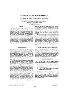
2.3 Camera Calibration Problems can arise from aspects related to various settings of the camera and specifically its calibration and positioning. Important parameters that affect the overall performance are the angle of vision in horizontal (pan) and vertical direction (tilt) (see Figure 1). Large values in these parameters deteriorated the performance of the system, since they alter significantly the appearance of plate and the characters to be identified by OCR. In such a case, the imaging system probably would need an image restoration technique, prior to LPR. Another issue that should be addressed carefully is the shutter speed of the camera (if a still camera is used). Low shutter speed is a particular problem if the targets are moving at an excessive speed, causing a blurry appearance of the vehicle and the license plate. To avoid blurring it is ideal to have the shutter speed of the selected camera set less than 0.001 seconds for free flow applications. In slowmoving traffic or in access/control/billing points where the vehicles stop when the shutter speed may be lower.
IEEE Intelligent transportation systems magazine •
60
• Spring 2014
4 1
1
2 3 4
10
8
2 3
5 6
9
7
{ 4
7
D = 1,8”
5 8
6
Fig 2 Artificially created images for measuring discrimination ability.
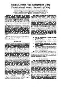
Moreover, angle of vision (pan and tilt) also influences the value of the shutter speed. Lower values of pan and tilt decrease the need of high shutter speed as the difference between frames in this case is smoother. Usually the shutter speed is selected by a trial an error procedure according the application needs. Another question that should be solved is the calculation of the effective distance in relation to the camera specifications. The effective distance is a function that has several parameters related to the camera, the discrimination ability of the LPR algorithm and the physical dimensions of the smallest plate to be identified. Therefore, suppose that: ■■ �A camera used in a LPR testbed has 3.2 million effective pixels (e.g. 2048 # 1536 pixel images), CCD at 1.8 inch with a typical width/height ratio equal to 4/3, and lens 3x adjusted to f = 24 mm (equivalent to 114 mm camera format). ■■ �D iscrimination ability of the algorithm is 20 # 68 pixels and (note that 20 pixels is typically the lowest height of identifiable characters in most OCR engines) ■■ � T he smallest plate to be identified n is a rectangular object of 33 cm width and 10 cm height. We have to note that, the discrimination ability indicates the smallest plate that can be identified by the system correctly by the LPR system (including the OCR module as well). Discrimination ability is usually measured by trial and error or by artificially created images that contain many copies of a cropped vehicle image with its plate in different resolutions and size (see Figure 2). The effective distance for successful license plate recognition is calculated as follows. Suppose that a typical CCD has a width/height ratio equal to 4/3 as shown in Figure 3: Therefore, the angle { is:
3
Fig 3 CCD representation of the example.
CCD width = 1.8 ) cos { (inches) � CCD width = 36, 6 mm
(2)
CCD height = 1.8 ) sin { (inches) � CCD width = 27, 5 mm.
(3)
In order to calculate the object distance the equation (4) is used:
where, f, l, D and L are depicted in Figure 4. Another important measure is the physical dimensions of one pixel in the CCD. This can be found from the effective pixels and the actual dimensions of the CCD. Thus, the square pixel dimensions are given by the equations: CCD_width horizontal effective pixels � = 36.6 mm = 17.9nm 2048
pixel_width =
CCD_height vertical effective pixels � = 27.5 mm = 17.9nm. 1536
(5)
pixel_height =
(6)
The dimension of the license plate in the CCD (Figure 5) is calculated as: �
license plate in the CCD : width = 68 pixels x 17.9 nm (7) = 1.21 mm
�
license plate in the CCD : height = 20 pixels x 17.9 nm = 0.36 mm. (8)
3 4
{ = arctan ( ) & { = 36, 8 degrees .�(1)
Since the CCD is at 1.8 inches its dimension in cm is given by (2) and (3):
f = D ,�(4) l L
Hence, the object distance is:
D=
0.33 (m) # 24 (mm) L# f = . 6.5 meters .�(9) 1, 21 (mm) l
IEEE Intelligent transportation systems magazine •
61
• Spring 2014
Lens Real Object Dimension L
Image Object Dimension l
CCD
1,21 mm 0,36 mm License Plate Object Distance Focal Length f D
Fig 4 Representation of parametes f, l, D and L.
Fig 5 Dimensions of a plate in the CCD.
The above distance D, is actually the maximum distance between the target (vehicle) and the camera using the specific camera and lens. Of course the above-calculated distance could be increased if more expensive lenses and special equipment are employed. A useful link for selecting cameras and lenses can be found at http://www. cctv-information.co.uk/i/ An_Introduction_to_ANPR.
to motorway exit). To this end, practical applications of VrI are numerous focusing on analysis of travel behavior for transport planning purposes. Specifically, the derivation of section travel times (time taken by a vehicle to go from one point to another) is useful to transportation engineers for traffic operations, planning and control. Accurate travel times and densities can be instrumental in travel reliability, feedback control, vehicle routing, traffic assignment and traveller information systems. If vehicles are tracked along consecutive points, then partial origin/destination demands can even be measured instead of estimated [1],[2]. In addition, the problem of analog toll billing could be addressed with a robust VrI system, as shown in Figure 6. Moreover, Vehicle Manufacturer/Model Recognition (VMMR) is a sophisticated computer vision application based on LPR that appeared lately in the literature [3],[4]. For VMMR, the spatial position of a license plate in a captured image or video frame plays an important role in the segmentation of a distinctive reference area from the vehicle (see Figure 7). From this area, which is usually
3. Applications 3.1 Security Applications In the past decades, the issue of security has become more significant and the need for effective security systems has intensified. Many areas were marked as restricted such as borders, government buildings, embassies, power plants and military camps, since illegal access can have serious consequences for homeland security. LPR check points provide control management, granting access only to vehicles authorized to enter limited zone areas.
3.2 Ticket Issuing, Billing Ticket issuing in parking lots and tolls are actually among the first and most common applications of LPR. They are also the easiest LPR implementation, since vehicles either stop before the check point (parking lots), or pass with low speed from a specified lane (toll). Applications include the detection of various traffic violations (e.g. speeding, bus lane occupancy) and the identification of stolen or uninsured vehicles. For the latter task, an updated record of such vehicles by the authorities is crucial.
Vehicle B Reidentified
Vehicle A
Vehicle A Vehicle B
Vehicle A Reidentified
3.3 Other Applications License plate recognition, as a means of vehicle identification, may be further exploited in various ways, such as traffic management, analog billing in highways and Vehicle Manufacturer/Model Recognition (VMMR). Traffic management and analog billing is based on Vehicle re-Identification (VrI). VrI is the process of matching vehicles from one point on the roadway to another (e.g., from motorway entrance
Analog Billing:
Vehicle B
Fig 6 Analog toll billing through license plate recognition.
IEEE Intelligent transportation systems magazine •
62
• Spring 2014
proportional to the license plate, important local features could be retrieved that as the logo area or other vehicle “biometrics” (i.e. headlight shape, dimensions, distance from symmetry axis etc.). Of course, robust classification schemas and appropriate training are critical issues to be addressed. Beside vehicle classification, vehicle matching and/or verification are also possible, assuming that a template image of a vehicle has been archived into a database in advance.
4. Image Processing/Analysis in LPR Image analysis is the extraction of meaningful and useful information from digital images by means of Digital Image Processing (DIP) techniques. DIP is a form of signal processing for which the input is a digital image or a video sequence. The output of DIP may be either an image or a set of features useful for solving application-based problems. In a License Plate Recognition (LPR) pipeline, the input is a color or grayscale image and the output is a string of characters. LPR typically includes three steps, license plate detection, character segmentation and optical character recognition. In all three steps, there is plenty space to implement image analysis and artificial intelligence schemas. This section provides a brief reference of relevant literature, according to their major methodology in the three typical steps of license plate recognition. Details on performance, execution time, image resolution and other relative issues in the literature can be found in [5].
As far as extraction of the plate region is concerned, techniques based upon combinations of edge statistics, texture and mathematical morphology are the most popular. They are based on the property that license plates can be
Table 1. Categorization of methods for license plate detection in images. Approach
Description of Major Processing
Binary image processing Mathematical morphology
Tophat operations
Edge features
Vertical edges Vertical Sobel operators
Binary algorithms
Connected component analysis Shape analysis, geometric attributes/spatial moments
Gray level processing Global image analysis
Filtering and enhancement
Partial image analysis
Horizontal image scanning (N row distance)
Statistical measurements
Statistical block processing Statistical Haar-like features selected by AdaBoost training schemes
�Region segmentation (adaptive thresholding)
Dynamic/adaptive thresholding Mean shift segmentation
�Hierarchical representations
Quadtree decomposition and vector quantization
4.1 License Plate Detection (Image Processing, Artificial Intelligence)
P� robabilistic object tracking in video
Condensation algorithm and differential evolution
License plate detection aims at the spatial identification of the license plate within the input image. To this end, a feature extraction process initiates to reduce the amounts of data in the image, which is usually a coarse-to-fine strategy.
Transforms
Gabor filters in block-based processing Hough transform, windowed-HT Radon transform Wavelet transform Generalized symmetry transform
Color processing
Mask
Color model transformation
Color segmentation in RGB/HSI model
Fuzzy sets
Color and spatial positioning fuzzy sets in RGB/HSI model Fuzzy c-means
Texture features
Texture-based measurements
Histogram manipulation
Histogram intersection
Wmask = n : Wplate Hmask = k : Hplate [Example: n = 4, k = 2]
License Plate
Classifiers W mask
Statistical classifiers
Nearest neighbor search Mahalanobis distance Support vector machines
Computational intelligence
Genetic algorithms, genetic programming, discrete time cellular neural network, pulse coupled neural network, time delay neural network, multilayered feedforward neural network, convolutional neural network, fuzzy neural network
H mask License Plate
H plate
W plate
Fig 7 Segmentation of a distinctive frontal view of a vehicle. IEEE Intelligent transportation systems magazine •
63
• Spring 2014
viewed as irregularities in the texture (or brightness) of the image and therefore abrupt changes in the local characteristics of the image, manifest probably its presence. Since this method does not depend on the edge of licenseplate boundary, it can be applied to an image with unclear license-plate boundary and can be implemented simply and fast. As far as extraction of the plate region is concerned, a fast categorization of methods that were reported in the literature is shown in Table 1, along with the description of the main processing method. An extremely crucial step in License Plate detection (as well as in character segmentation in the following stage) is Connected Component Analysis (CCA). CCA is a vital technique in binary image processing that scans an image and labels its pixels into components based on pixel connectivity, (either 4-connected or usually 8-connected). Once all groups of pixels have been determined, each pixel is labelled with a value according to the component it was assigned to. Extracting and labelling of various disjoint and connected components in an image is central to many automated image analysis applications as many helpful measurements and features in binary objects may be extracted. Such features include area, orientation and aspect ratio, just to name a few of them that are very frequently integrated to image processing algorithms for license plate detection (see Figure 8). Then, using simple filtering techniques, binary objects with measurements that exceed the desired limits can be eliminated in the following algorithmic steps. Full shape attributes for binary image processing are listed in Table 2.
4.2 Character Segmentation (Image Processing) The license plate candidates determined in the plate location stage are now examined in the character’s segmentation phase. A large diversity of techniques to segment each character after plate localization in the image has been developed as shown in Table 3, where they are grouped according their methodology. Reviewing the literature, it was evident that the method that exploits vertical and horizontal projections of the pixels is the most common
Object 1
Object 1
Measurement
Value
Area
268 Pixels
Aspect Ratio
3,5
Orientation
-7 Degrees
Euler Number
-8
Compactness
0.54
....
....
Fig 8 Shape analysis in binary object 1 (license plate).
Table 2. Categorization of shape analysis for binary objects. Shape Analysis 1. �Topological attributes
3. Moments
4. �Shape orientation descriptors
1.1 Euler number
3.1 Surface
4.1 Bounding box:
1.2 Convex hull
3.2 Center of gravity
• �height, width, area, ratio
1.3 Perimeter
3.3 Inertia
4.2 �Image-oriented bounding box:
1.4 Area
3.4 Oriantation
• �height, width, area, ratio
2. �Geometrical attributes
3.5 Major ellipse axis
4.3 �Radius measurements:
2.1 Compactness
3.6 Minor ellipse axis
• �min, max, angle, ratio
and simplest one. Projections are used for character segmentation in many text recognition systems. Obtaining a binary image, the idea is to add up image columns or rows and obtain a vector (or projection), whose minimum values allow us to segment characters (see Figure 9). It should be emphasized that many character segmentation modules incorporate more than one methods (e.g. adaptive thresholding, CCA and object filtering followed by the projection method etc.). Usually, there is a preprocessing phase that removes the noise, enhances the image, and moreover, it detects, centers and normalizes the license plate image. The output of the preprocessing module is still an image representing the corrected/enhanced license plate. Character segmentation is needed to perform character recognition, which fully relies on isolated characters. Incorrectly segmented characters are not likely to be successfully recognized. In fact, most of the recognition errors in the LPR systems are not due to missing recognition power but to segmentation errors.
4.3 Optical Character Recognition For the recognition of segmented characters, numerous algorithms that appear in optical character-recognition applications, utilizing statistical classifiers, computational intelligence architectures and common pattern matching techniques are employed as shown in Table 4. As already discussed at the section related to the calculation of the effective distance, character height should be at least 20 pixels if character recognition is required. Note however, that sometimes even this resolution is not enough as dirt, physical damage, and unpredictable shadows degrade the recognition performance. Practically, OCR should successfully handle any ambiguity that may arise due incorrectly segmented characters from the previous character segmentation step. Very good
IEEE Intelligent transportation systems magazine •
64
• Spring 2014
Table 3. Categorization of methods for character segmentation. Approach
Detected LP
Description of Major Processing
Binary image processing
Corrected LP
Projections
Vertical and horizontal projections of the pixels in the binary image
Binary algorithms
Connected component analysis Shape analysis and geometric attributes/ spatial moments Measurements: height, width, area, orientation, centre of gravity
Mathematical morphology
Thinning, thickening, pruning techniques
Contours
Bug following Shape driven active contour model
Vertical Projections
Segmentation
Fig 9 Shape analysis in binary object (license plate).
Table 4. Categorization of methods for plate character recognition.
Gray level processing Histogram manipulation
Intensity-gradient scattergrams Valley search in the intensity distribution Cumulative distribution functions, background/foreground entropy
R� egion segmentation (local/ adaptive thresholding)
Block processing, threshold in each block
Transforms
Hough transform
Approach
Description of Major Processing
Classifiers Statistical classifiers
Hidden Markov models Support vector machines Likelihood models in tree hierarchy
Computational intelligence
Multi layered feedforward neural networks Adaptive ressonance theory neural networks Self organized neural networks Probabilistic neural networks Learning vector quantization neural network
Classifiers Statistical classifiers
Markov random fields Hidden Markov chains Pattern matching
results have been reported using neural networks and statistical classifiers. Given also that OCR engines are quite mature and that they are continuously improved over time, the developers focus their attention to OCR improvement in sets of ambiguous characters (1/I, 0/O, 0/D, 2/Z, 8/B, and 5/S) rather than redesigning or retraining character recognition modules.
Template matching
A = (P # I ) %, (10)
5. Performance Calculation Due to the wide range of applications of LPR systems there is no actually a common consensus on how developers or end-users can assess safely the overall performance. Different approaches have been reported according to the specific nature of each test-bed and the special conditions that are needed. This means that the performance is strongly affected by the characteristics of the physical installation, the operation prerequisites (in-door or out-door), the vehicle flow etc. Basically, three methods are usually implemented. The first method to measure the overall success rate is by calculating separately the percentage of: (i) license plates correctly detected and (ii) characters correctly recognized. Both percentages should be verified by an expert supervising a sufficient test sample. This total accuracy A is figured as shown in Equation (10).
Normalized cross correlation Hausdorff distance Root mean squared error (RMSE) for all the template shifts Image partition: zoning, projections, contour distance, segment count
where P and I are plate detection and character recognition percentage. On the other hand, the second method assesses overall performance in a more pessimistic (strict) formula. Total character recognition rate is now related exponentially to the number of characters expected n. Therefore, equation (10) is converted to equation (11) below. A = (P # I n ) %.�(11)
The difference between the above methods is obvious. Suppose that we have a sufficient test set that includes 3000 images of single vehicle, and each plate contains 7 characters. If the expert verifies 96.0% correct LP detection (2880
IEEE Intelligent transportation systems magazine •
65
• Spring 2014
over 3000) and 98.0% overall character segmentation in a follow-up analysis (19757 over 20160), then we have 94.1% success using equation (1). However, assuming an independent character recognition rate of 98.0% for each one of the 7 characters in the plate (as equation 2 indicates) the overall performance falls to 83.3%. The third (and most accurate) method dictates that we have to consider only the percentage of the correct interpretation of entire plate content. Thus, equation 11 becomes as follows:
A = (P # C ) %.�(12)
In equation 12, C is the percentage of cases with successful recognition of all characters in the plate. Considering the example of the previous paragraph, if the 2016019757 = 403 erroneously classified characters correspond to the first character of different plates, then equal number of license plates is not identified correctly. As a result, the number of plates with correct interpretation of entire content is 2880-403 = 2477, and therefore C equals to (2447/2880)%-85.0%. Then, the overall performance following equation (3) falls to 81.6%. In summary, we could say that the most important indication for the evaluation of a license plate recognition system is the definition of the conditions under which the performance is estimated. In addition, the proper indication of the failure cases and the various limitations during the process are essential for determining the system accuracy. The article written by Liam Keilthy [6] may provide a good starting point for the development of a generic approach for operators to ANPR system performance assessment.
6. Radio Frequency Identification (RFID) RFID is used to improve production logistics, automate access control and parking, secure border roadways, automate toll collection, manage traffic flow. RFID tag is a memory chip, which could be implanted in the license plate during the vehicle registration process by the appropriate transportation authority, becoming a standard identifier for all vehicles. The data stored on this RFID tag can be retrieved anytime via fixed and mobile reading devices by radio communication at any point needed (sometimes even in heavy traffic). In conjunction with camera-based systems RFID could drastically improve LPR performance in cases where the latter fails. Instead of having image/video processing and OCR, RFID tags could broadcast vehicle identity to nearby receivers under all out-door conditions. Active RFID and Passive RFID are fundamentally different technologies that are often evaluated together. While both use radio frequency energy to communicate between a tag and a reader, the method of powering the tags is different. Active RFID uses an internal power source (battery) within
the tag to continuously power the tag and its RF communication circuitry, whereas Passive RFID relies on RF energy transferred from the reader to the tag to power the tag. There are several issues to be taken into consideration. For instance, passive tagged vehicles can only be read individually from a reader no more than 12 meters (40 feet) mounted over the lane. In addition, another limitation occurs from the line-of-sight requirement and the fact that the reader may process one vehicle each time, making such an approach inadequate in heavy traffic situations. On the other hand, active tags in license plates (i) work in longer range (up to 100 meters) without the necessity for line-of-sight, (ii) transfer bigger data packages and (iii) operate in any speed and direction, as they process data faster. However, they are battery-operated and the installation cost is multiple.
7. Discussion 7.1 Operation Challenges The challenges associated with LPR can be attributed to the following factors: ■■ � Environmental/illumination conditions: The major problems revolve around the varying light levels encountered during a twenty-four hour period and the effect those lighting changes have on the image captured for license plate location and processing. In any outdoor environment, illumination not only changes slowly as daytime progresses, but may change rapidly due to changing weather conditions or passing objects (i.e., clouds). ■■ �D ifferent dimensions/type: This is an important restriction when a LPR system is expected to handle a variety of plate formats according to the standardization regulations in each country. Color, size, character fonts, alphanumeric sequence, official stamps, province and country codes are some of the varying parameters that may confuse a LPR system. ■■ �Occlusion: Even in a perfectly fine tuned LPR system with correct settings, plates may be partially occluded by other objects. For instance, in an image with a group of vehicles, some vehicles may be partially occluded by others. ■■ � Plate condition: The appearance of plates is directly affected by unpredictable reasons such as dirt, shadows from bumpers, sun reflections, improper placement and generally unacceptable physical appearance (e.g. discolored or distorted characters etc).
7.2 Super-Resolution Enhancing license plate text in real traffic videos is a challenging problem for LPR which is not sufficiently addressed in the literature and still has plenty of room for research. In special occasions, (e.g. terrorism acts), human
IEEE Intelligent transportation systems magazine •
66
• Spring 2014
operators need the support of unconventional image/video processing techniques to decipher the content of a license plate. This can be achieved with super-resolution (SR). Super-resolution is a method that works effectively when several low resolution images contain slightly different views of the same object. Thus, global information about the object is gathered. An SR image of the license plate is obtained by fusing the information derived from multiple, subpixel shifted, and noisy low-resolution plate views. The best case is when an object moves smoothly in the video, such as most cases in LPR. Motion detection and tracking (i.e. motion compensation for finding corresponding areas in subsequent frame) is used to create an SR license plate view. Excellent works on this topic can be found in [7],[8].
7.3 LPR Goes Mobile From 2008 developers moved away from static installations, providing also mobile LPR (m-LPR). Usually m-LPR indicates that the platform is designed to operate in situations where mobility is required or checkpoints occasionally need to be moved. Mobile LPR, which includes also LPR units installed inside (on-board) vehicles, is now possible since new technology offers us cheaper and smaller processing units, cameras and smart programmable cameras. All this equipment may be portable or even be installed in vehicles, allowing real time LPR. Various mobile architectures are proposed, in which algorithms are able to compensate for certain variables that can affect the LPR ability to produce an accurate result. It is evident that mobility affects the overall performance and there are noteworthy challenges related with m-LPR. The major challenge is the need to operate in various surroundings. So, all problems affecting LPR systems apply to m-LPR with the extra issue of the unpredictable environment. If we also consider the case of on-board LPR, where camera views change as the vehicle moves, the LPR algorithms should fulfill stricter criteria and parameterizations. In these cases, action cameras should be employed that are equipped with digital image stabilization and lens distortion correction algorithms ensuring that footage recorded will look stable. The digital image stabilization technology corrects camera shakiness for smoother recording, while lens distortion correction offers the option to automatically remove the fish-eye look that is common with action cameras.
7.4 Conclusions In this paper we present a brief tutorial on the well-studied, but not fully solved, problem of LPR. The main goal is to provide the young researcher with sufficient information about this topic and possible solutions giving emphasis on image processing techniques. To this end, the reader is encouraged to visit www.lpr-tutorial.info in order to down-
load Matlab Code and sample images. Sample images may be also downloaded from the Medialab License Plate Recognition database at http://www.medialab.ntua.gr/research/ LPRdatabase. html. Medialab License Plate Recognition database contains a large image and video dataset that has been collected and grouped according several criteria (type and color of plates, illumination conditions, various angles of vision and indoor or outdoor images with or without infra-red auxiliary units. We anticipate that researchers engaged in LPR or in related projects will report their results on this publicly available set or alternatively will contribute to the enrichment of this test database.
About the Author Christos-Nikolaos E. Anagnostopoulos was born in Athens, Greece in 1975. He received his Mechanical Engineering Diploma from the National Technical University of Athens (NTUA) in 1998, and the Ph.D. degree from the Electrical and Computer Engineering Dpt., NTUA in 2002. From 2008, he serves the University of the Aegean as Assistant Professor in the Cultural Technology and Communication Department. He is a member of the Greek chamber of Engineers and member of IEEE. His research interests include image processing, computer vision, neural networks and artificial intelligence. He has published more than 120 papers in journals and conferences, in the above subjects as well as other related fields in informatics. He also serves as associate editor for the IEEE Intelligent Transportation Systems Magazine.
8. References
[1] C. C. Sun, G. S. Arr, R. P. Ramachandran, and S. G. Ritchie, “Vehicle Reidentification using multidetector fusion,” IEEE Trans. Intell. Transport. Syst., vol. 5, no. 3, pp. 155–164, Sept. 2004. [2] C. N. Anagnostopoulos, T. Alexandropoulos, V. Loumos, and E. Kayafas, “Intelligent traffic management through MPEG-7 vehicle flow surveillance,” in Proc. IEEE John Vincent Atanasoff Int. Symp. Modern Computing, 2006, pp. 202–207. [3] A. Psyllos, C. N. Anagnostopoulos, and E. Kayafas, “Vehicle model recognition from frontal view image measurements,” Comput. Stand. Interfaces, vol. 33, no. 2, pp. 142–151, 2011. [4] H. Yang, L. Zhai, L. Li, Z. Liu, Y. Luo, Y. Wang, H. Lai, and M. Guan, “An efficient vehicle model recognition method,” J. Softw., vol. 8, no. 8, pp. 1952–1959, 2013. [5] C. N. Anagnostopoulos, I. Anagnostopoulos, I. Psoroulas, V. Loumos, and E. Kayafas, “License plate recognition from still images and video sequences: A survey,” IEEE Trans. Intell. Transport. Syst., vol. 9, no. 3, pp. 377–391, Sept. 2008. [6] L. Keilthy, “ANPR System performance,” in Proc. Parking Trend Int., June 2008. [7] Y. Tian, K. H. Yap, and Y. He, “Vehicle license plate super-resolution using soft learning prior,” Multimedia Tools Applicat., vol. 60, no. 3, pp. 519–535, 2012. [8] K. V. Suresh, G. M. Kumar, and A. N. Rajagopalan, “Superresolution of license plates in real traffic videos,” IEEE Trans. Intell. Transport. Syst., vol. 8, no. 2, pp. 321–331, June 2007.
�
IEEE Intelligent transportation systems magazine •
67
• Spring 2014