encompasses all aspects of a product's life cycle from ... product architecture analysis and redesign method is ..... Proceedings ASME Design Theory and.
Proceedlngs of EmDeSQn2003: Third International Sympslum on Environmental$ Conscious Design and Inverse Manufacturing Tokyo, Japan, December 8-11.2003
EcoDesign2003/1D-8
Life Cycle Modularity Metrics for Product Design Patrick J. Newcomb Georgia Institute of Technology Ei.newcomb(iimarc.natech.edu
David W. Rosen Georgia Institute of Technology david.rosenciime.natech.edu
Abstract
two measures of modularity were proposed one that measures module correspondence between several viewpoints (known as the correspondence ratio CR), and another that measures coupling between modules (known as the cluster independence Cl). The algorithm and measures were applied to the analysis and redesign of an automotive center console, and the results reflected our intuitive understanding of the original center console design and predicted the results of our redesign. These measures incorporate only configuration information of the product, and hence, can be used before detailed design stages. For more details, see [l]. The work described in this paper extends the previous work by presenting an analysis and redesign method that applies to hierarchical product architectures. A partial automotive interior example is used to demonstrate the method. This interior example includes the center console kom [I], but adds two more assemblies: an instnunent panel and a center module. The introduction of the two additional assemblies enables the investigation of the impacts of more complicated configuration changes, such as moving subassemblies ffom one assembly to another.
In thispaper, a methodfor the analysis and redesign of hierarchical product configurations is shown. including previously developed measures of modulariv. The meihod is applied to a partial auiomative interior consisting of a cenier consolefrom and insirumeni panel. The confgw+ation goes through three redesigns, and fhe derails are analyzed using ihe modulaniy metrics. The redesignr are guided by nnalysis ai different levels of ihe produci hierarchy (e.g., the assembly and subassembly levels). In faci, the analysis at differeni levels enabled beffer-informed redesig”. The method uses only configuration design information and is iherefore usefil at the early siages of design. The results show thai the measures reflect our intuitive understanding of the concept of product modularity. yei also indicate that ihe mehics are open forfurher refiement.
1. Introdudion. The concept of Design for the Life Cycle encompasses all aspects of a product’s life cycle from initial conceptual design, through normal product use, to the eventual disposal of the product. A product’s architecture, determined during the configuration design stage, plays a large role in determining the product’s life cycle characteristics. In this paper, a product architecture analysis and redesign method is presented Modularity of product architectures with respect to life cycle concerns is defined and applied to the analysis of architecture characteristics. A principal hypothesis underlying this work is that a high degree of life cycle modularity can be beneficial across all viewpoints of interest. The life cycle viewpoints of interest in this work are: functionality, recycling, endof-life, and service. This work helps a designer’s to reconfigure a product (using modularity as a strategy) to improve its recycling, end-of-life, and service characteristics, while maintaining system functionality. This work presented here builds on previously developed modularity metrics and a productpartitioning algorithm. In the previous work (see [I]),
&769520460 0 2w3 IEEE
Bert Bras Georgia Institute of Technology bert.bras@,me.gatech.edu
2. Product Architecture and Modularity Configuration design is the process of synthesizing product structures by determining what components and sub-assemblies are in the product and how they are Connected and arranged spatially. Establishing the product structure involves the selection of modules and the design of module interfaces. Modularity is the concept of separating a system into independent pam or modules that can be treated as logical units. The way in which a product is divided into modules has a great effect on the way it is assembled, disassembled, serviced, and retired (among other things). The challenge, then, is to develop methods for configuration design that enable designers to meet requirements on modularity applied to all l i e cycle viewpoints of interest (assembly, service, recycling, reuse, etc.). Ulrich and Tung [Z]gave a summary of Merent types of modularity and their advantages and
~
251
disadvantages. Benefits include simplified assembly and disassembly, improved serviceability, easier maintenance, and differential consumption. Potential costs of modularity include redundant physical architecture (due to decreased function sharing), excessive capability due to standardization (designing for the most rigorous application), and the potential for static product architectures and excessive product similarity. The authors also contend that modularity is a relative property that depends on two characteristics: 1 Similarity between the physicd and funcfionnl architecture of the design, 2 Minimization of incidental interaitions between physical components. Accordingly, complete modularity is achieved when there is a one-to-one correspondence between the physical and functional architectures. This concept is used as the premise for modularity in our work. The functional architecture of a product refers to the arrangement of a product’s overall function($ into subfunctions. For example, a car’s center coniole has many functions: hold cups, store items, and support arm (to name a few). The degree to which a product’s physical architecture (the actual arrangement of components and modules) resembles its functional structure is directly proportional to its modularity. With several life cycle viewpoints to be considered for a product with many components, determining the actual degree of correspondence between viewpoints is not easy. Therefore, we use a systematic method known as Matrix Decomposition. Steward‘s Design Structure Matrix (DSM) [3] model has been used to identlfy orderings of tasks and the organizationally difiicult aspects of the design process [4]. The DSM is a square matrix where the row elements and column elements are the design tasks to be performed. The matrix is binary; elements are filled based on whether or not one design t+sk depends on information &om another. The m a e ’ i s then partitioned into blockdiagonalflower triangular form with the blocks indicating coupled groups of tasks and the remaining entries below the diagonal indicating information transfer to later tasks. Eppinger and coworkers have also used the DSM extensively in design organization, based upon product struclure. In [ 5 ] , a method for the analysis of product design decompositions is detailed. The DSM partitioning method is used for two purposes in that paper: 1) organization of the development teams and 2) the definition of product architecture. This is accomplished by.using componenis as the row and column elements (as opposed to design tush in Steward‘s case). The method involves decomposition of the system into elements, the documentation of the
interactions between the elements, and clustering (or integrating) the elements into architectural and team chunks. (Architectural chunks are equivalent to product modules.) The energy, material, information, and spatial (EMIS) interactions between elements are documented, and the DSM can be partitioned with respect to any of these viewpoints. In this paper, matrices that capture certain l i e cycle information me partitioned into clusters to indicate modular product architecture(s) eom different life cycle viewpoints. Instead of using the EMIS interactions, this research uses the life cycle viewpoints stated in Section 1 (recycling, end-of-life, and service characteristics, while maintaining system functionality).
3. Method of Analysis Corresponding to the two aspects of modularity presented in Section 2, we have previously proposed two measures of modularity (see [I]): a measure of how well modules e o m different viewpoints correspond, called the correspondence ratio (CR), and * a measure of incidental interactions between modules, called cluster independence (Cl). In order to measure the modularity of a product, it is first necessaty to determine the product’s modules; to do so, we will briefly describe the architecture decomposition algorithm used in our research.
-
3.1. Architecture Decomposition Product architecture decomposition into modules is performed by converting a matrix into block-diagonal or lower-triangular form. Other techniques exist for computing partitions of a set, but matrix decomposition has a beneficial visual interpretation. We use. the algorithm developed by Kusiak and Chow [6] because it is versatile enough to handle symmetric, asymmetric, and non-square matrices. Typically, square matrices are used in decomposition. A matrix containing material compatibility information is square, with the design’s components as the row and column headings. A “1” in the matrix cell indicates good compatibility between the row and column component, a “2” indicates some compatibility, a “3” indicates limited compatibility, and a “4” indicates total incompatibility. The rule for decomposition of the material cluster the 1’s (good compatibility matrix is. compatihility measures) into block-diagonal form, followed by the 2’s, etc. For a detailed walkthrough of the iterative steps on an example matrix, see [l].
-252-
From a post life intent viewpoint, non-square matrices can be used if each component is to be designated for one of four intents: recycling, reuse, incineration, or landfilling. In that case, the matrix would be 4xm, where m is the number of components. ,
3.2. Modularity Measures Modularity is defined as the degree to which two architectures correspond. Complete modularity is reached when there is a one-to-one correspondence between the two architectures. The intersection of two modules does not tell us how well the modules correspond, however. Our measure of correspondence, the Correspondence Ratio (CR), is defined as:
where Vi(x) denotes the module in viewpoint Vi that contains component x and 1x1 inGcates the cardinality (number of elements) of set X. If the correspondence between two modules is high, CR is close to 1, while if correspondence is low, CR is close to 0. The CR is a good measure on a module-by-module basis, but does not allow comparisons of two designs very well because the different designs may have considerably different modules. A better evaluation of module correspondence for an entire.product is the average CR for all modules in the product, called CRoveral1:
-2% (2) #Modvlss Similar to CR, CR,,verall = 0 indicates no correspondence between viewpoints. It approaches unity when the individual module CRs approach unity. In order to address the second properly of modularity, minimizing incidental interactions, a Cluster Independence (Cl) measure was developed. Minimizing incidental interactions is analogous to decreasing the amount of dependence between modules. In ow design for the life cycle context the dependence between modules is represented by the physical connections that exist between the modules. For example, for material recycling, C O M ~ C ~ ~ O Uwithin S a module are not of greatest concem Rather, connections between modules are important since they need to he broken in order to separate modules for recycling. Therefore, our second modularity metric depends upon the ratio of intra-module connections to the total number of connections in the product Intramodule connections are those that are in blocks along the matrix diagonal of a decomposedmatrix,referred to
as “on-block-diagonal-connections.” informal manner as:
CI is given in an
CI is calculated using the on-block-diagonal measures because this yields the trend of zero being the.worst and unity being the best for the metric. Theoretically, the maximum CI = 1.0 will’occur only when all of the l i s are on the block-diagonal, meaning that no intermodule co&ctions are in the product. That is, the product is a disjoint set of modules, in which case it would probably be seen as a set of several products. The minimum CI is 0.0 and exists only in the case where each module consists of only one component. We propose an overall measure of modularity as the product of C b V d and CI,which ranges between 0 and 1, inclusive (Eqn. 4). A weighted sum formulation could have been used, but we prefer the multiulicative form since its minimum value is 0. Modularity = (C%ve&(CI)
(4)
33. Analysis and Redesign Method Now that we have established ow method for matrix decomposition and computation of modularity mehics, we can present the analysis and redesign method ked. . Given: CAD model of product, material data, and user input on service and post-life intent. 1. Analyze existing design (see Step 5 ) 2. Generate product coniigurations by introducing new modules 3. Generate new module configurations 4. Propose new materials and service and post-life intents for components 5 . Analyze design: Construct design matrices for various viewpoints Perform inabix decomposition(Sec. 3.1) ‘ e Calculate modularity mehics 6. Ifacceptable, then stop, Else, use results to guide redesign at Step 2, 3, or 4.
The main steps of this method are meant to guide the redesign of the product by encouraging the designer to think broadly about the overall structure of the design and generating the primary product modules and their structure, before focusing on materials and post-life intents for specific Components. In practice, it is often convenient to first propose minor changes (Step 4) and studying their effect, before exploring broader product changes (Steps 2, 3). Such studies can guide the broader redesign activities.
-253-
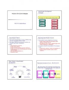
module, is introduced in-between the original hvo modules; several subassemblies are moved to the center module (Steps 2 , 3 , 4 , 5). Figure 1 shows the hierarchical module structure of the partial automotive interior. The center console and instrument panel are the main modules for the first three analyses. The center module is added during the third redesign step (fourth analysis). During each analysis, the product arcbitecm analysis and redesign method was applied. Modularity mehics were applied to each main module and to the entire interior assembly in a hierarchical manner, and then redesign suggestions were generated.
4. Casesttidy In Figure 1, two levels in the hierarchical structure of a (partial) car's interior are shown: the assembly level (center console, instrument panel) and the subassembly level (storage bin, end cap, armrest, radio, etc.). What is not shown (for brevity and clarity) is the component level. For example, the original armrest consists of seven components. In addition to analyzing the modularity of the whole interior shown in Figure 1, the modularity of the interior's assemblies (the center console and the instrument panel) can be analyzed separately. As will be shown through the case study, this ability to analyze the design at two levels of the product hierarchy provides more insight than would be gained only through analysis at the highest level. This insight enables more intelligent redesign to be performed. Following the method in Section 3.3, a series of four analyses and three redesigns of the interior will he used to illustratethe application of the method: .. Design the interior consists of an 1. Ori@ instrument panel and the center console fium the previous work (Step 1); 2. First Redesign - material, service intent, and postlife intent changes are made to the center console and instrument panel (Steps 4,5); 3. Second Redesign some components are moved fium the center console to the instrument panel plus some other con6guration changes (Steps 3 , 4 ,
4.1. Existing Design The original interior assembly consists of a center console and an instrument panel as shown in Figure 1. We ignore the center module and the CM-fascia until the third redesign The center console is the same one used in [I]. The new Inshument Panel @) consists of five subassemblies: the main horizontal punel, the glove box (slorage),the climute confrol, the radio, and the air vents (uiflow). As in the Center Console (CC), the IP's components are made *om a wide mix of materials. Post-life intents and service intents were assumed for the E ' as was done for the CC. The CC and IP are not physically attached to one another, but are completely separate modules of the Interior. To establish a baseline, the modularity of the original Interior was evaluated. For brevity, we will not show all of the matrices involved in this case study, but they can he found in [7]. We are interested in the
-
-
5); 4. Third redesign - a third module, the center
--_____---L
Center module absorbs several subassemblies from other two
Figure 1 -Hierarchical module structure; showing previous work (shaded) and major configuration change of final redesign -the addition of the center module
-254-
Material Recycling, Post Life Intent, and Service Viewpoints. A summag‘ of the modularity evaluation of the original Interior is shown in Table 1 (note that “dna” stands for “does not apply”). These results will be used for comparison to the redesigns performed later. To put it in perspective, the Interior is made up of 34 components with 44 connections between them. The original design gets divided into 28 modules when all of the Viewpoints are combined The Modularity measure of the Interior is 0.042 on a theoretical scale from zero to one, one being “the best”. So is 0.042 a bad score? We will discuss that when comparing it to OUT redesigas of the Interior. Table 1
- Summary of OriginalInterior Design
Post Life Intent
Not shown in Table 1, but also of interest is what happens to the modularity of the center console (CC) separately. Separate and the instrument panel (E’) modularity evaluations were done for both the Original CC and the Original LP. The Center Console contains 19 of the 34 components and 27 of the 44 connections. It divides into 14 modules when all Viewpoints are combined and has a Modularity measure of 0.051. The Instrument Panel has 15 components that divide into 14 modules. It is no wonder, therefore, that the Modularity measure for the E’is very low, at 0.015. It s e e m there is room for improvement
4.2 First Redesign The fkst redesign performed involves material, post-life intent, and service intent changes only components were not reananged in the assembly. This serves as a good comparison to the original design as well as a good baseline to more complicated
-
configuration design changes that involve moving components from one assembly to another. The glove box and ductwork components were changed from polypropylene QP) to ABS, and the glove box door was simplified from a mix of materials to polycarbonate QC). These changes serve to help simplify the material mix. The Post Life Intent was also changed to almost exclusively “recycle” and “landjill” as post-life strategies, except for the armrest’s foam and pad that are designated as “reuse”. The
changes to the Center Console were shown in [l]. The only difference is that the configuration of the cup holder was not changed to the simple rigid design Seen in the redesigned CC in [l]. Since a baseline of material, post-life intent and service intent changes was the goal, this con6guration change is saved for the second redesign of the Interior. The results of the first redesign (Redl) are shown in Table 2. As can be seen in Table 2, the overall modularity improved from 0.042 to 0.089 tbrough these design changes focused on material substitution and changes in post-life intent.
4.3 Second Redesign of Interior Now we will look at a more complicated design change that involves moving and reconfiguring components. In a vehicle, it is reasonable for certain components to be in either the Center Console (CC) or the Instrument Panel p).In this redesign case, two components, the ashtray and DCqower have been moved *om the CC to the IP. In order to house the DCgower and ashtray, a center fascia component was created and is also attached to the lower pad. Furthermore, the cup holder was simplied from a retractable one to a static cup holder, eliminating the cup fascia. The results of the redesigned interior are shown in Table 2 as R e a . For all Viewpoints combined, the Modularity of the Interior improved slightly eon 0.089 to 0.097 (compared to the first redesign). Moving the DCqower and the ashtray h m the CC and simplifying the cup holder improved the Material Recycling, PLI, and Service Viewpoints of the CC. However, the CC’s overall Modularity score (not shown in Table 2) declined slightly from 0.146 to 0.141, despite an increase in the Cluster Independence from 0.481 to 0.667. What hurt the Modularity measure was that the Cc‘s CR (for all Viewpoints combined) declined h m 0.303 to 0.212, indicating that although the individual Viewpoints improved, the Viewpoints do not correspond weU with each other when combined. In other words, the Cc‘s architecture from each of the three Viewpoints diverged h m one another. For the Instrument Panel, all of the Viewpoints resulted in an increased number of modules, while correspondence between modules improved slightly. However, the declines in the CI measure outweighed the CR improvements to yield a slightly lower overall Modularity score of 0.025 (down from 0.027). In retrospect, introducing the DCgower, the ashtray, and center fascia to the IP were bound to cause this outcome since each consisted of a mix of materials.
So how can the overall Modularity of the Interior improve from 0.089 to 0.097, yet for both the CC and the IP, the overall Modularity scores declined? The answer lies in the parts that make up the overall Modularity metric: the Corresgondence Ratio (CR) and the Cluster Independence (CO, especially taking into consideration the respective contributions that the CC and IP make. The CC accounts for 24 of the 44 total connections in the Interior, and the IP accounts for the remaining 20144. Additionally, the CI for the CC increased significantly (boom 0.481 to 0.667) and the IP's CI decreased slightly (from 0.118 to 0.100). So the result was a heavier weighting on the increased score. The resulting Interior CI is an increase fiom 0.341 to 0.409 (19.9%) fiom Redesign 1 to Redesign 2. In contrast, the CR slips for the Interior from 0262 to 0.238 (10.9 %), hut only half as much as the CI increased. Agaiq the CR for the CC decreased significantly, agd increased for the IP, but the CC is much less weighted than the IP in the CR score.. The Correspondence Ratio, based on the number of modules. obtained a 1/23 connibution from the CC and the remaining 16/23 contribution bom the IP.
The same goes for the service intents of the components. The radio, climate .control, cup holder. and ashtray are all components that. function through moving parts. These need more frequent servicing: than, e.g., a bracket in the CC. So the service intent scheme for the IP and CC should become purer. Table 2 - Comparison of Original Design to First, Second, and Third Redesigns of Interior
'
4.3 Third Redesign of Interior The third and final redesign consists of some serious contiguration design changes by creating a third subassembly of the Interior, the Center Module (CM). As in many vehicles today, there can be an area in the automotive interior that is not quite the center console, nor does it exactly belong to the Ip. Often, many of the functions of the Interior are embodied in components that reside in this Center Module - the radio, 'cup holder, etc. As seen in our Interior example so i k , these components have existed in the IP the CC. This final redesign of the Interior wiU move 4 subassemblies - the radio. climate coatroL. CUD = holder. and ashtrayhghter - from'their original msitions in the IF' or CC &-the new Center M o h e . y o house these 4 subassemblies. a comwnent called the Center Module Fascia (&-fascLajwas created (see Figure 1). The only physical relationship the CM has with the rest of the interior is that it is attached to the IP through a connection between the IP's Uooer Panel and the W s CM-fascia. There are no connections to the Center Console, It is expected that aggregating all of these comoonents into the Center Module will make the IP and the CC more modular with respect to material recycling because the material makeup of each will be simpli6ed In addition, complicated subassemblies such as the radio cannot be melted down and recycled like many of the components of the CC. Therefore, the post-life intent of the CC and Ip can also be purified.
..
.
.
Red2 Red.?
I 1
23 23
I 1
,238 263
1 1
18/44 (.409) 16/42 (381)
1 1
.097 .I00
The results of the Modularity evaluation on the three-subassembly redesign are shown in Table 2 under Red3. For all Viewpoints combined, this third redesign produces the highest Modularity score yet: 0.100. However, the third redesign is barely better than the second redesign. This is counterinmitive to the predictions made of higher Modularity scores through introducing the third subassembly, the Center Module. To gain insight, we need to examine the three subassemblies individually. The CC actually took another step backwards with respect to the overall Modularity measure for all Viewpoints combined, going from 0.141 (Redesign 2) down to 0.131. The CR stayed virtually the same (to 0.211 from 0.212), but the CI measure declined from 0.661 to 0.619. The IP overall score improved boom 0.025 to 0.029. Driving most of this improvement (though slight) were improvements to C1. However, the CR moved in the apposite direction. In the third redesign, the IP lost the ashtrayDCqower, the radio, and the climate control to the new Center Module - dramatic changes. In the second Redesign, the IP had 18 components with 20 Connections. Tbh was exactly halved in the third
redesign to 9 components with IO connections. what is lefl of the IP exhibited poor correspondence between the Viewpoints - the CR score dropped fiom 0.250 in Redesign Two to 0.143 in Redesign Three. The initial Center Module has 10 components with IO C O M ~ C ~ ~ Oand ~ Spulls together all of the complicated subassemblies the radio, climate control, cupholder, and DCqoweriashtray. All of these subassemblies have moving components and are made of mixed materials. This d e s for complicated material recycling and servicing. Consequently, all of the components except for the CM-fascia (created to house the four subassemblies) were slated for the landfill as the Post Life Intent swtegy. Looking at Table 3, we can see that the number of modules for all Viewpoints combined is IO. So-what we have is 10 disjoint components, each one its own module. In this situation, we do not have any on-block-diagonal connections, and therefore, the Cluster Independence measure is Oil0 = 0. Since there are no “blocks” in the ma& bigger than one cell, there can he no on-block diagonal connections, a6. by our definition a component is not really connected to itself. Since Modularity iS the product of the CR and CI measures (see E q e 4), the overall C M ’ s Modularity equals zero. Therefore, the Center Module does not contribute positively at all to the overall Interior Modularity score. ~
,
Table 3
- Summary of Center Module Evaluation
Mat1 Recycle
post Life Intent
Service w/ conn
Au V P S
5/10 (SOO)
dna
I
1
10
4/10 (.400) . ,
I ,417 I 0110 (0.000) I
0
5. Discussion In the third Interior redesign, the clustering of the complicated subassemblies into the Center Module should have had some benefits (intuitively). Servicing should have been somewhat simplified because most of the components that require more fiequent servicing are in one area, making them easy to access. End of life dismantling should have been simpler too: because all of the complicated assemblies in the CM were slated for the landfill, the entire CM can be ripped out and landiilled. However, these benefits are not being fully captured by the modularity metrics used in this work. The Correspondence Ratio appears to be true to its intent, and its scale fiom zero to one seems a good representation of the degree of modulatity. However,
the Cluster Independence could be refined to capture the missing detail. As previously mentioned, the Cluster Independence metric is binary two components are either connected or not connected. The metric does not take into consideration the number and type of fasteners that make up the more general connection. Certainly, two components are easier to separate if they are connected by a single 2-way snap-fit than by 2 sonic welds and a screw. Also, the need for separation should drive the type of fasteners. If something needs to be separated only once - at the end of the product*s life - perhaps sonic welds are fine, since they may be broken &er product integrity is no longer a factor. However, if a component needs to be separated and then reassembled, as in the case of service, then a screw or a snapfit is a more appropriate choice. The application of the Cluster Independence measure (and the Correspondence Ratio) also needs to be tested with different types of modularity. The Center Module seems to exhibit what Ulrich and Tung [2] refer to as “Bus Modularitf‘, i.e., a single bus is the backbone for several components or modules, as in a computer motherboard. There are 5 components attached to the CM-fascia, in a bus-like fashion, one for each subassembly (radio, climate control, cup holder, ashtray), and one for the DCqower. Since the CM-fascia is the lone component that is not destined for the landfiu and for sometimes (rather than “oflen”) service frequency, each of the connections to it is an off-hlock-diagOnal (five in all). There are a total of IO connections in the CM with 5 on-block-diagonal connections, yielding a CI = 5/10, That is the best that can be done in this coniiguration, with a hinary sense of connections. If the actual inter-component fasteners were tallied, the CI would approach unity as the number of on-blockdiagonal connections (like those within the radio) would outpace the off-blockdiagonal connections (those between the radio and the CM-fascia) as the level of detail increased. Suffice it to say that the Cluster Independence is ripe for further investigation and rehemeni
-
6. Conclusions In this paper, we demonstrated a design and analysis method for hierarchical product structures. The goal is to achieve better p d u c t configuration through higher modularity fiom several life cycle viewpoinb simultaneously. The analysis and redesign method was described, along with modularity metrics, and then applied to a partial automotive interior. This interior consisted of an Instrument Panel and Center Module added to a Center Console from previous work. The
-251-
method was applied to the Interior as a whole and to the assemblies individually (Center Console, Instrument Panel, and Center Module). We were able to predict that certain conf~guration design changes would improve the Modularity measure of the Interior, showing that the measures match our intuition. Importantly, these measures use only configuration design information, and can therefore be used early in the design process. Also, the modularity measures can be applied at any level of a product hierarchy (above the component level). In fact, the analysis at different levels of product hierarchy provides better insight than analysis only at the top level. Thus,configuration changes are better informed. We have seen, however, that there are still snme aspects with the Correspondence Index in particular that could be improved upon. Recall that the Center Module seems to exhibit the concept of Bus Modularity [Z]. Modularity ‘type was not considered when the metrics used in this paper were developed. Different types of modularity may yield different results and have Werent “ideals” conf~gurations. This would be and interesting topic for future research.
[6] Kusiak A and Chaw, W S , 1987, “Efficient Solving of thi: Group Technology Problem,” J. of Monufocruring Systems, 6(2),pp. 117-124.
[7] Newcomb, P 1, 2001, Implications of Modulariry on Product Design for the Life Cycle, M.S. Thesis, Georgiii
Institute of Technology.
Acknowledgments Financial support from the National Science Foundation under grant number DMI-9414715 is gratefully acknowledged. We also acknowledge the Chrysler Corporation (now DaimlerChrysler) for their donations of automotive components.
References [I] Newcomb, P J , Bras. B A, Rosen, D W, 1998, ”Implications-ofModularity on h d u c t Design for the Life Cycle,” ASME J. of Mechmicnl Design. Vol. 120, No. 3, pp. 483-90. [2]ULrich,KTandTung,K, 1991,‘T~mdamentalsofRoduet d Meeting Conference,DE Vol. 39, Atlants, pp. 73-80,
Modularity,”Proceedings ASME W m m A
[3] Steward, D V, 1981, System AM&=& d MaMponenf: hccrure. Strategy mdDesign,Petmeelli Boob, New Y&
[4] Smith, R P,Eppinger, S D, and Gopal, A, 1992, ‘Testing an Engineering Design Iteration Model in an Experimental Setting,” Proceedings ASME Design Theory and Merhodology Conference, DE-Vol. 42, pp. 267-276.
[SI Pimmler, T U and Eppingu, S D, 1994, ‘%&ation Analysis of h d u a Decompositions,” Proceemjlgs ASME Design Theory md Methodology C o n f m c e , DEVol. 68, pp. 343-351.
-258-


![Modular product development - AlvaresTech [PDF]](https://m.moam.info/img/260x300/modular-product-development-alvarestech-pdf_6479e7f7098a9ee0288b45ec.jpg)