and breaking glass, in addition to the muffling face masks, prohibit rescue workers ... a long-range radio technology to send this data to the fourth and final major ...
University of Virginia LifeLine: Improved Communication and Informatics for Fire and Rescue Workers
LifeLine: Improved Communication and Informatics for Fire and Rescue Workers Team Members: Daniel Ceperley Minh Duc Nguyen Andrew Perez-Lopez Arun Thomas
Faculty Mentors: Mircea Stan Ronald Williams
Computer Society International Design Competition May 2002
Abstract Emergency rescue workers respond rapidly to a variety of dangerous situations trying to save lives. In so doing, they put their own lives on the line. In interviews with Charlottesville rescue workers, we discovered that they lack critical information while in a fire. For example, they do not know whether the temperature is high enough to melt their equipment, or if their air-tank is almost empty. Furthermore, rescue workers within a team cannot even talk to each other but instead rely on non-verbal communication, such as tapping each other on the shoulder. With the innovative use of Bluetooth wireless technology, LifeLine provides a rescue worker with data and voice communication capabilities. Sensors monitor information such as the ambient air temperature and the rescue worker’s air-tank pressure. A Bluetooth Personal Area Network transmits data between the sensors and a display in the rescue worker’s face mask. Bluetooth also provides voice communication among members of a rescue team. The sensor data and voice communication our system provides helps rescue workers to better plan and execute their operations. With LifeLine, rescue workers can save lives while reducing the risk to their own. This report describes the LifeLine project from requirements analysis to prototype testing and verification. The report explains the design and implementation of our first-generation prototype, including the decisions and tradeoffs made throughout the development process. Finally, the report details our plans for future development, with particular emphasis on a second-generation prototype of LifeLine.
1
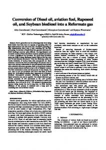
1 System Overview 1.1 System Description In addition to the dangers inherent in emergency work, rescue workers face many hardships in just using their equipment. The first major problem is that thick smoke obscures dials and indicators, making it difficult to read important information about equipment status and the surrounding environment. The smoke can be so dark that it is difficult to see more than a few inches ahead, much less read a dial on an air-tank regulator strapped to a rescue worker’s belt. Without accurate information, rescue workers have to make educated guesses of how much time they have left before they run out of air. The second problem is that even though face masks are crucial for rescue workers’ protection, they muffle voices that are already hard to hear. Roaring fires, screaming sirens, and breaking glass, in addition to the muffling face masks, prohibit rescue workers from speaking with each other, forcing them to communicate by tapping each other on the shoulder or using other non-verbal signaling. The major problem is that rescue coordinators have little knowledge of what is happening inside an emergency area. A fire captain may receive sporadic updates over very high frequency (VHF) radio “walkie-talkies”, but rescue workers cannot afford to transmit constant reports. To address these problems, we designed LifeLine, which consists of Sensors, Head Units, Radio Hubs, and a Base Station (Figure 1). The sensors periodically gather information about the environment and equipment status of an individual rescue worker. An example of a typical sensor would be an external temperature sensor or an air-tank pressure sensor. This information is transmitted via Bluetooth radio to the second major subsystem, the Head Unit. The Head Unit has a microphone, a speaker, and a display, all within the face mask. When a rescue worker wants to communicate with his teammates, he speaks into the microphone, and the Head Unit transmits his voice over Bluetooth to the third subsystem, a Radio Hub, which is carried by one member of each team. The Radio Hub uses Bluetooth to send the voice transmission to every other member of a team. The Radio Hub also collects sensor data from each Head Unit within a team and uses 2
a long-range radio technology to send this data to the fourth and final major subsystem, the Base Station. The Base Station will typically be located out of immediate danger, for example on a fire truck near a burning building. At the Base Station, rescue coordinators can monitor the status of their personnel and communicate with them. Temperature Sensors
Air Gauges
Base Station Radio Hub
Head Units
Diagram Key: Bluetooth Link: Radio Link: Head Unit
Head Unit
Radio Hub Temperature Sensor
Air Gauge
Temperature Sensor
Carried by one fireman
Base Station
Air Gauge
Carried by one fireman
On board fire truck
Figure 1: LifeLine System Overview
1.2 Performance Requirements During the requirements analysis phase of our development process, we interviewed Charlottesville rescue workers and asked them what functionality they would find useful [1] [2]. In summary, LifeLine needs to meet the following performance requirements:
1. Real-time voice with at least telephone quality audio . 2. Fast and simple to set up and operate because valuable time cannot be spent configuring complicated electronics in an emergency. 3. Inexpensive because many fire departments operate on a volunteer basis and cannot afford expensive additional equipment. 3
4. Small and lightweight because rescue workers already carry 40 lbs. of equipment. 5. Low-power because the Sensors and Head Unit have to run on batteries.
1.3
Design Methodology
In order to complete such a complex project within a limited amount of time, we recognized that it was crucial to have an effective design strategy. From our interviews with local rescue workers, we produced a detailed list of requirements for the system [1] [2]. We then determined a realistic set of milestones and tasks for member of the team could complete in parallel, including extra time to allow for unexpected delays. We prototyped potential risks early in the development process to avoid any problems that could produce significant delays later. Our project milestones also included evolutionary prototypes that eventually became the components of our system. This iterative process, with continual development, testing, and redesign, was successful for our team.
1.4
Innovations
The LifeLine system has a number of innovative features. First, LifeLine provides critical information to the rescue worker in real-time. This is a vast improvement over the current situation in which, for example, rescue workers must guess how much air-time they have remaining. Second, LifeLine provides voice communication among a team of rescue workers. This allows them to better plan and coordinate their activities since they no longer have to rely on hand gestures and other non-verbal signaling. Finally, LifeLine includes real-time monitoring and analysis of rescue workers’ data at a central command post. With LifeLine, rescue coordinators can watch over their workers’ safety by monitoring information from heart and respiration rates to ambient temperature.
4
2 Design 2.1 Objectives In order to meet LifeLine’s requirements, we decided to set the following goals. LifeLine will:
1. provide short-range voice and data communication. 2. be easy to configure and use 3. provide clear, accessible environmental data and status information to the user. 4. provide an interface for monitoring and analysis of real-time data by the rescue coordinator. To address these objectives, Bluetooth technology was a natural choice. Bluetooth transceivers automatically detect each other and configure themselves into a network with sufficient bandwidth to transmit both voice and data. Initially, we had concerns that Bluetooth would not work in the hostile environment of a fire, but according to a communications expert, the smoke and radiation in a fire would not interfere with Bluetooth transmissions [3]. Bluetooth’s low cost and recognition as a widely adopted wireless technology standard also made it the right choice for our system. The main problem with current equipment readouts is that they are affected by the external environment. A rescue worker surrounded by smoke can barely read the dials of his equipment, even if they are only inches from his face. A good way of avoiding these problems is to display information inside the self-contained breathing apparatus (SCBA) face mask. A panel inside the face mask displays information in front of the rescue worker’s eyes so that he does not have to search for a dial or readout. Inside the mask the rescue worker’s face is protected from the smoke and debris, and system components would benefit the same protection. Rescue workers’ hands are often encumbered with heavy gloves, making it difficult to manipulate buttons and switches. In order to keep the system simple, we decided that a voice activation system would provide a good hands-free interface. Spoken commands are a natural way to operate a system and they do not require additional equipment that might hinder the rescue worker.
5
Currently, rescue coordinators have little knowledge of what is happening inside an emergency area. With LifeLine, real-time data is gathered and recorded for analysis. Rescue coordinators are more informed so that they can organize effective rescue operations.
2.2 2.2.1
Components Sensors
There are many types of sensors that are potentially useful for rescue workers. For the sake of brevity, we discuss only a few: an external temperature sensor, an air pressure sensor, a breathing rate sensor, a heart-rate monitor, and a motion detector. In our system rescue workers enhance their awareness of their surroundings by wearing a number of sensor modules connected via Bluetooth to form a Personal Area Network (Figure 2). Each sensor module contains a sensor, a microprocessor, and a Bluetooth module. The sensors collect data that is retrieved by the microprocessor and transmitted via Bluetooth radio to the rescue worker’s Head Unit, where the data is displayed. The sensor modules are heavily insulated so that the electronics are not affected by high temperatures. The insulation in firefighting equipment is so effective that the firefighter does not know the temperature of the surrounding air. This can lead to disaster because he may enter a room that is too hot and have his gear fail. In order to prevent this, a temperature sensor module can be placed on the outside of the gear, and the rescue worker can read the ambient temperature from the display in his face mask. This way, he knows to leave the room if it is too hot for his gear. Additionally, by monitoring the trends in temperature, LifeLine can detect an imminent flash-over and warn the firefighter to evacuate (a flash-over occurs when a room’s temperature rises to the point in which everything in the room suddenly ignites) [4]. After speaking with rescue workers, we determined that the best place for the temperature sensor is on the top of the helmet. In a fire, firefighters often crawl across the floor to stay below the smoke and heat; however, they periodically raise their heads to check around the room and in the process their helmets can melt because of temperature
6
Temperature Sensor
Air Pressure Sensor Heart-Rate Sensor
Head Unit BreathingRate Sensor
Motion Detector
Figure 2: Rescue Worker’s Personal Area Network gradients. By placing the temperature sensor on the top of the helmet, it will detect the hottest temperature affecting the firefighter’s gear. Currently, a rescue worker monitors the pressure in his air-tank by reading a dial mounted on his shoulder. Thick smoke makes it difficult to read the dial. By placing an air pressure sensor on the air-tank, the rescue worker can monitor the pressure from the display inside his mask. This way he will be warned to evacuate if his air pressure is too low. LifeLine offers another benefit. Not only are air-tank pressure sensors easier to read, but some simple calculations on the values allow us to determine how much air time remains. Clearly, this is valuable information that will greatly assist in planning. Heart and breathing-rate sensors are useful for our application as well. A rescue coordinator can monitor the status of all of his personnel and determine if any has stopped breathing or been injured.
7
The rescue workers we interviewed told us that they carry Personal Alert Safety System (PASS) devices [1] [2]. These devices sound alarms if a rescue worker stops moving so that his teammates will rescue him. The problem is that there is so much background noise that the alarm may not be heard. The motion-detector module works like a PASS device; however, it is more likely to catch attention. When a rescue worker stops moving, the motion detector sends a warning message to the his Head Unit, which relays it to the rest of the team and to the rescue coordinator. The other team members will immediately know their teammate is injured and begin searching for him. The rescue coordinator will also know that someone has been hurt and can organize a mission to retrieve him. The Personal Area Network (PAN) cannot be configured completely automatically since each sensor module must connect to a specific Head Unit. To make sure the sensor modules connect to the correct head unit, the rescue worker performs a simple initialization process. A synchronizing device is loaded with the Bluetooth MAC address of the Head Unit. Sensors can then be set to connect only to that MAC address. This would typically be done prior to a rescue mission, but could even be done during one.
2.2.2
Head Unit
The Head Unit consists of a speaker, a microphone, a voice activation system, a display, an embedded microprocessor, and a Bluetooth transceiver. This component receives data from the sensors in the rescue worker’s PAN, and sends and receives voice data. All sensor data from a rescue worker’s sensors are sent to the Head Unit. This data is displayed to the rescue worker and is also sent to the Radio Hub. The display in the face mask cannot be so large as to obstruct the view of the rescue worker. The small size of the display limits the amount of information that can be displayed concurrently. To accommodate more than just a couple of sensors, the display cycles through all of the sensor data. The rescue worker can request to view specific sensor data using voice activation. Voice activation technology is very appealing as an interface for a system like LifeLine because it offers flexibility and ease not found by any other control mechanism. There are no buttons to 8
manipulate, and all that needs to be learned are key words, which anyone can do. However, there are concerns with voice activation. The technology is good, but it may have trouble dealing with all of the aural inputs in an environment so noisy as a fire. While voice activation is not yet reliable enough to depend upon for critical functions, we decided that its many benefits would justify its use for non-critical functions. For example, it would not be dependable enough to control voice communication, but it is used to advance the display cycling.
2.2.3
Radio Hub
The Radio Hub plays a dual role: it helps to coordinate voice communication within a team of rescue workers and it serves as a bridge between the team-level network and the Base Station. All data and voice transmission between the Head Units and the Radio Hub is accomplished using Synchronous Connection Oriented (SCO) links (Figure 3). The difference between SCO and ACL links is that SCO links provide guaranteed latency on the connection, but they do not retransmit lost or incorrect packets. In contrast, ACL links provide guaranteed delivery of packets, but since this is done through retransmissions, there are no guarantees on latency. Since voice transmissions are inherently time-dependent, SCO channels are necessary to ensure smooth voice transmissions [5]. Even though Bluetooth’s limit of three SCO links per piconet restricts the size of a team to include at most three members, this is not a significant limitation since we learned in our interviews that there are rarely more than three members in a team [1] [2]. Even so, we thought that we could create a more flexible design to accommodate more than just three team members. We explored the possibility of expanding the original piconet of three SCO links to a scatternet that would relay SCO data between piconets; a Bluetooth module could receive SCO data as a slave in one piconet, switch to another piconet where it is a master, and forward the same data to its slaves. Upon further research into Bluetooth scatternets however, we discovered that it is not possible for a Bluetooth device to have SCO links in two piconets at the same time. The piconet clocks would gradually drift until the two SCO links would eventually overlap [6]. We decided to limit our 9
Head Units
Radio Hub Head Unit
Radio Hub
Diagram Key: Bluetooth Link:
Head Unit
Head Unit
Head Unit
Figure 3: Head Unit to Radio Hub Topology design to Bluetooth’s specifications, especially since the three voice connections are adequate for our purposes. In designing the voice communication protocol, we developed two different designs and evaluated the tradeoffs between them. In the first design, only one rescue worker within a team can speak at a time. The following describes the protocol for the first design:
1. Coordination among Head Units is accomplished by means of a token system. If no one is currently speaking, the Radio Hub has the token. 2. If a Head unit desires to speak, it must request the token from the Radio Hub. 3. If no other Head Unit has the token, then the Radio Hub will grant the request. 4. Once the Head unit is granted the token, it may send voice for as long as desired, and stops sending voice by relinquishing control of the token and returning it to the Radio Hub. 5. When one Head Unit is sending voice, the Radio Hub receives the voice, and broadcasts the voice to the other Head Units within the team. 6. A Head Unit requests and releases the token by using voice activation 10
In the second design, all the Head Units can send voice at the same time through a pseudo-open channel. An open channel in which all the Head Units can speak simultaneously is simulated through the following:
1. Each Head Unit continuously sends voice to the Radio Hub. 2. The Radio Hub receives the voice streams from each of the Head Units within a team and mixes them into one voice stream. 3. The Radio Hub broadcasts the mixed voice stream back to each of the Head Units. Comparing the two designs, we decided on the second design. At a quick glance, the second design is much simpler than the first. A more cogent reason for choosing the second design is that the first design requires requesting a token, which requires voice activation commands. We believe that current speech recognition technology is not reliable enough to be used for such a critical part of the system. Furthermore, it could happen that a rescue worker is unable to release the token because he is knocked unconscious and thereby prohibits communication among the rest of his team. The second design can achieve coordination as to who speaks by using the “Over” and “Over and Out” radio convention that rescue workers are already familiar with from using walkie-talkies. Communication to the Base Station will be accomplished via a long-range, high-power transmission technology. The design of our system does not depend on any specific long-range technology, but some good choices are IEEE 802.11b or walkie-talkie radios equipped with modems. Depending upon the situation, it may even be possible to use Bluetooth with an amplified transmission signal, which has a range of 100 meters.
2.2.4
Base Station
The Base Station is where the rescue team coordinators monitor, in real-time, the status of all of the rescue workers. They can monitor each individual rescue worker’s sensor data, and if required, can speak to any team of rescue workers. In this way, the rescue team coordinators can alert rescue 11
personnel to an injured team member or issue an order. Furthermore, the coordinators have the option of broadcasting a message to all active rescue workers. An example of such a broadcast is an order to evacuate a building that is about to collapse.
2.3 Fault Tolerance Concerns In a safety critical system such as LifeLine, it is crucial to minimize the possibility of system failure; however, should the system fail, it should do so gracefully. Although our current implementation is merely a prototype of a full LifeLine system, we have begun to address such concerns. A potentially disastrous situation is created if the Head Unit and the various sensors cannot communicate. For example, a rescue worker could run out of air without realizing it until it’s too late. In order to prevent such a scenario, we have implemented a ”heartbeat” safeguard. At mutually agreed upon time intervals, the sensors send a signal to the Head Unit if data is not already being sent. The Head Unit records the number of heartbeats missed in succession and keeps a running average of missed heartbeats. If a certain consecutive number of heartbeats or a certain percentage of the heartbeats are not received, the system notifies the rescue worker that the link is not behaving reliably. The rescue worker is notified of the malfunction by both visual and auditory means to ensure that he does not miss the malfunction indication. The sensors also monitor their battery charge levels. If they fall below a certain threshold, the user is notified of this as well. If the various Head Units cannot communicate to the Radio Hub, then the rescue team members cannot communicate with each other or the Base Station. A similar heartbeat scheme is used here. If the Head Unit is not transmitting voice, it sends a heartbeat signal to the Radio Hub. If the Radio Hub does not receive the heartbeats, then it notifies the other members of the team that they have lost communication with one of their team members. The Radio Hub also transmits a heartbeat signal to each of the Head Units. The Head Unit notifies the rescue worker if it does not receive the heartbeats from the Radio Hub. In this scenario the Head Unit then reconfigures itself as a pseudo-Radio Hub. One of the Head Units becomes 12
the master of the new piconet; it establishes SCO connections to the other members of the team. The choice of which Head Unit becomes the master is arbitrary. The master of the piconet can transmit to the slaves just as before. If one of the slaves wishes to transmit however, then the voice data must be forwarded from the sending slave to the master to the other slave. Thus, the latency is increased. The slaves cannot communicate with each other directly because a Bluetooth device cannot have SCO links in two piconets simultaneously. There is a tradeoff inherent in this scheme: the master of the new piconet has two SCO links; therefore, it can only have one ACL connection. Thus, only one sensor module may be in active mode at a time; the others will be in parked mode. Since each sensor module must switch from parked to active mode when they wish to transmit, the sensor data cannot be updated as frequently; however, this limitation applies only when the Radio Hub has failed. In addition, the Radio Hub transmits a heartbeat to the Base Station when it is not transmitting voice. This is to ensure that the Base Station is receiving the rescue teams’ data and voice transmissions. The rescue workers are notified if there is a problem with the Radio Hub to Base Station link. The Base Station also uses a heartbeat so that the rescue coordinator knows if his links to the rescue teams are operational. It is important to remember that we have designed a prototype system, and a final LifeLine system would be subject to a more thorough failure analysis.
13
3 Implementation 3.1 Overview
Sensors
Laptop-A
Laptop-B Bluetooth Figure 4: LifeLine Demonstration Overview Our prototype (Figure 4) demonstrates all of the main functions of our system. A sensor module consists of a temperature sensor, a microprocessor, and a Bluetooth module. Data is collected by the sensor, retrieved by the microprocessor, and transmitted via Bluetooth radio to LaptopA which represents a Head Unit. Another Head Unit laptop (Laptop-B) displays data received from the sensor module and also transmits voice to Laptop-B. Laptop-B also functions as a Radio Hub and Base Station. The Base Station software displays data collected from a group of rescue workers. Most of the data is simulated, but one set of data is actually from the sensor module, the same data being shown on the Head Unit display of Laptop-A. In this way, the functionality of each component of the system can be observed, as well as the performance characteristics of the system as a whole. 14
The sections that follow will give insight into the implementation details of each of the components of our project and clarify the decisions made at each stage.
3.2 3.2.1
Components Sensors
To demonstrate our system, we decided to implement two sensor modules: a temperature sensor module (Figure 5) and a pressure sensor module.
Figure 5: Photograph of the temperature sensor module. The central microprocessor is a Microchip PIC16F877 (referred to as a PIC processor). This microprocessor was chosen because of its low power consumption and low cost. It has digital input/output (I/O) ports, analog to digital converters (ADC’s), and a serial port. The microprocessor controls the Bluetooth module via the serial port. The ADC’s make reading the pressure sensor easy and the digital I/O ports are ideal for reading the temperature sensor. Low power consumption 15
was also a critical factor in choosing a microprocessor because the sensor modules must last a long time on battery power. During normal operation, the PIC only draws 2mA supply current at five volts. Furthermore, the PIC can be put into sleep mode, during which it draws only 10.5µA supply current at five volts. For our demonstration, the sensor modules are powered by a typical nine volt battery. We wrote a Bluetooth stack for the PIC16F877 using embedded C and assembly so the microprocessor could communicate with the Head Unit. We first wrote this stack on a computer using C++ and tested it by having it communicate with the rest of the system. Once the bugs were resolved, we ported the stack to the PIC and tested it again. The temperature sensor we chose is a Dallas DS18S20. This temperature sensor works in a room temperature environment. We decided not to use a high temperature, fire-ready, sensor because they are expensive and we cannot safely produce fire temperatures during a normal demonstration. The DS18S20 is an ideal sensor for our application for many reasons. First, it consumes very little power. It can run in “parasite power” mode, where power is not directly supplied to the sensor but is drawn from the data line. In typical operation, the temperature sensor draws only 1.5µ at five volts when performing a temperature conversion, which takes only three quarters of a second at most. During the rest of the time, the sensor draws only 750nA at five volts. The schematic for the temperature sensor module is shown in Figure 6. The key components in the schematic are: the PIC microprocessor which controls the module, the temperature sensor which measures the air temperature, and the serial port which connects the microprocessor to the Bluetooth module. Including support circuitry, the temperature sensor module draws a little over 10.5mA in supply current when it is “awake” with an additional 30mA for the serial port. When the module is asleep, it only draws a little more than 5mA. The pressure sensor module is very similar to the temperature sensor module. It differs only in that the temperature sensor is replaced by a pressure sensor, two amplifiers, and a MOSFET switch. The MOSFET switch is used to turn off the pressure sensor when it is not being polled. Each 16
Figure 6: The schematic for the temperature sensor module. amplifier can also be turned off by the microprocessor. During normal operation, the amplifiers draw about 1mA total of supply current and when they are turned off they take only 19µA of supply current. The amplifiers can be turned off for most of each second and turned on for a brief period of time because they take only 20µs to wakeup. Again, the pressure sensor module consumes very little power so it has a very long battery life.
3.2.2
Head Unit
The Head Unit receives regular updates of sensor data, displays the data in the mask GUI, and forwards the data to the Radio Hub.
3.2.2.1
Mask GUI
A Mask Demo program (Figure 7) was written to show how we envision a face mask with a mounted display panel. The program was written using Java, and it makes use of TCP/IP sockets to communicate with other subcomponents of the Head Unit.
17
Figure 7: Screenshot From Mask Demo Software 3.2.2.2
Voice Activation
For our prototype, we used Carnegie Mellon University’s open-sourced Sphinx II system for voice activation. First, we chose the phrases to be identified by the system, and then, using their supplied tools, we constructed a language model. Our program supplies Sphinx II with the language model we built, as well as voice data recorded from the microphone, and based upon the resulting suggestions, determines how to react.
3.2.2.3
Voice Communication
According to our design, all the rescue workers within a team can communicate with each other over an open channel. Communication over an open channel, however, requires that the Head Unit be able to send and receive voice at the same time (full-duplex). The soundcards of the laptop computers that we used in development can only send or receive voice one at a time (half-duplex). Given this limitation, only one of our Head Unit voice applications can speak at a time while the the other Head Unit voice application receives the transmitted voice. We believe that as a proof of 18
concept, even this limited communication is sufficient.
3.2.3
Radio Hub
When a Head Unit is transmitting voice, it sends the voice data to the Radio Hub, which forwards it to the other Head Units in the team. When a Head Unit is sending sensor data, the Radio Hub receives the sensor data, and forwards the data to the Base Station. In our implementation, TCP/IP sockets model the long-range communication between the Radio Hub and the Base Station. One of our first decisions was whether to use the Xircom CreditCard Bluetooth Adapters included in this year’s CSIDC project kit or to use the Ericsson Bluetooth modules from last year’s CSIDC project kit. The Xircom adapters are point-to-multipoint while the Ericsson modules are only point-to-point. The Head Unit and Radio Hub require multipoint capability because they need to maintain multiple connections at the same time. Since our system depends upon Bluetooth’s multipoint capability, we chose to use the Xircom adapters. Additionally, the Xircom adapters support SCO connections through a UART interface unlike the Ericsson modules. According to our design, SCO links provide voice communication among three team members per radio hub. Unfortunately, SCO links were not used in our final implementation. While working with SCO communication, we encountered two problems: the throughput was lower than the specification had led us to expect, and voice quality was severely degraded. According to the Bluetooth Specification, the throughput of an SCO connection is 64 kbps, making Bluetooth audio quality approximately the same as a GSM mobile phone [7]. The lowest quality voice that our sound cards could support was 64 kbps. While in theory, the SCO connection should support the desired voice traffic in real-time, there was actually insufficient throughput. In our tests, the measured throughput was 26.5 kbps, less than 42% of the expected value (Table 1). In the hope that newer releases of BlueZ’s SCO module would improve throughput, we continued working with SCO module. Since SCO links could not keep up with the voice traffic in real-time, we wrote a throwaway prototype that buffered the voice traffic on the receiving side and played the raw voice sample after the transfer completed. To our surprise, the voice quality was severely 19
Packet Type ACL (Xircom) SCO (Xircom) ACL (Ericsson) SCO (Ericsson)
Measured Throughput 450 kbps 26.5 kbps 100 kbps N/A
Expected Throughput 433.9 - 723.2 kbps 64 kbps 115.2 kbps N/A
Table 1: BlueZ Throughput Test Results
degraded. The original voice sample was barely recognizable from all of the static and noise. We believe that this loss in quality is because SCO packets are never retransmitted, so any packets that are not received correctly are lost. Given the low throughput and poor voice quality, we decided to use ACL rather than SCO links in our implementation. In the future, we hope to use SCO instead of ACL links.
3.2.4
Base Station
Figure 8: Screenshot from the Base Station Monitor Demo Software The Base Station Monitor Demo represents the Base Station component of our system (Figure 8). From a full-featured monitor, a rescue coordinator could monitor the status of all of personnel. This demonstration program was written in Java and uses TCP/IP sockets to communicate with other programs, thus decoupling this component from all other components in the system. According to our design, the Base Station is to be connected to the Radio Hub by a long-range radio technology. Since TCP/IP is arguably the most widely accepted networking protocol, it was a natural choice for this program. 20
The Monitor also has a number of example functions illustrating the possibilities available with this system. The Monitor records all data transmissions, allowing operations to be replayed after the fact. The Monitor also provides an example of real-time analysis that can be performed on incoming data. If a firefighter’s air pressure drops below 25%, or the ambient temperature rises above 75% of safety limits, he is flagged as being in potential danger, and his name is brought to the attention of the Monitor user.
3.3 3.3.1
Underlying Technologies Bluetooth
One major advantage of Bluetooth is that it is a wireless technology. In a system like LifeLine, the users are already encumbered with many pounds of equipment, and adding wires that can be easily be damaged is not safe or reliable. Second, some sensors will need to be outside of the protective gear of the rescue worker. In such an environment, it is preferable to have all of the electronics inside a heavily insulated package rather than have trailing wires back to the Head Unit. Wireless technology allows each of the sensors to be physically independent and allows for greater freedom in their placement. Bluetooth radio transceivers are perfect for small, inexpensive sensor packages. They broadcast over the limited range that we need, and they transmit omnidirectionally, so orientation is not an issue. Additionally, they are low cost, and they consume very little power, two very important issues for embedded systems. Finally, since we decided that we would need to use wireless technology for the voice transmission, it made sense to use a single technology to accomplish both of our goals. Bluetooth is that technology.
3.3.2
Operating System
In choosing a development platform for our project, we considered several important criteria. First, we wanted a stable operating system with which we were familiar. Second, we wanted an operating system that could support both the Ericsson and Xircom Bluetooth modules included
21
in the project kit. Third, we wanted an operating system that ran on a number of different architectures, particularly embedded processor architectures. Finally, since funds were limited for the competition, we wanted to choose an operating system that would not be prohibitively expensive to install on several development machines, as well as on demo machines. GNU/Linux met all of these criteria. It was available for unlimited use on as many machines as we wanted for no cost. Additionally, most of our team members have worked with it before. There are a number of Bluetooth protocol stacks written for GNU/Linux, and they support both types of Bluetooth modules. GNU/Linux is known for its stability and also for the wide range of architectures to which it has been ported. Since our system must eventually be an embedded system, this was also extremely appealing. The tradition of openness that exists within the GNU/Linux community also appealed to us because access to source code facilitated rapid development.
3.3.3
Bluetooth Stack
We gave much consideration to which Bluetooth stack to use. We researched several options, including Ericsson’s Reference Stack, Axis’ OpenBT stack, IBM’s BlueDrekar stack, and the BlueZ stack. Since we had opted to use GNU/Linux as our operating system, we could not use Ericsson’s Reference Stack. The remaining options were BlueDrekar, BlueZ, and OpenBT. While we liked the large feature set of BlueDrekar, we decided that its lack of available source code was so significant a detriment as to rule it out. Of the two open-sourced options, we chose BlueZ because its features were more suited to our application than were the OpenBT’s features. In particular, we liked the way that BlueZ chose to interface with Bluetooth - through the familiar BSD socket interface. BlueZ allowed us take advantage of our extensive experience with BSD sockets. We decided that over the duration of the project, the BlueZ stack would likely be better supported because it had been adopted as the standard GNU/Linux Bluetooth driver and is incorporated into the Linux kernel. Another benefit of the tight integration with the Linux kernel is an increase in performance. Since LifeLine is a real-time system, we thought any performance boost would be extremely important. Though both 22
the OpenBT and the BlueZ stacks were open-sourced, the copious amount of source code available from the BlueZ package sped up development considerably.
3.3.4
Voice Activation
In order to accomplish the voice activation for the Head Unit, we explored several options, including the Via Voice SDK from IBM, Carnegie Mellon University’s Sphinx II, as well as a number of hardware solutions. We came to the conclusion that IBM’s Via Voice was prohibitively priced, and so dropped it early on in our deliberations. That led us to choose Sphinx II. The Sphinx II has been developed for years by Carnegie Mellon University for the Defense Advanced Research Projects Agency and was recently relicensed so that the source code is freely available and royalty free for any purpose [8]. It is a powerful system capable of real time speech recognition and was more than adequate for our uses.
3.4
Additional Costs
All of our costs were accrued in making the sensor prototype boards. The parts used in the boards, and their costs, are listed in Table 2.
3.5 3.5.1
Testing and Verification Hardware
Testing of the sensor modules proceeded in a number of stages, beginning with basic hardware checks and proceeding up through full integration testing. First, we tested the temperature sensor itself to ensure that the PIC was reading the correct data from the sensor. To do this, we checked the temperatures against a thermometer. Second, we tested the PIC’s serial connection by attaching it to a computer. We verified that the temperature readings were being sent from the PIC, through the serial cable, to the computer. Third, we connected the Bluetooth module to the PIC and checked the temperature data sent from the PIC to the Bluetooth 23
Item Instrumentation Amplifier Operational Amplifier P-Channel MOSFET PIC Microprocessor Temperature Sensor Pressure Sensor RS232 Level Shifter 5 Volt Regulator Dual-Row Male Header 40 pin IC Socket 16 pin IC Socket 3.6864 MHz Crystal 9 pin Male DSUB Connector Modular 6 pin Telephone Jack PC Board Toggle Switch DC Power Jack 9 Volt Battery Clip Submini Push Button Switch Prototype Board Resistors, Capacitors, LEDs, Wire, Solder Total
Price $3.70 $5.65 $1.60 $8.98 $5.04 $18.90 $5.51 $0.81 $2.14 $2.89 $0.85 $0.88 $1.75 $6.57 $2.99 $1.00 $0.40 $1.25 $8.57 $10.00 $89.48
Table 2: Cost of items used in prototype sensor board.
and then to a computer. Lastly, we repeated these procedures with the pressure sensor module. Both the temperature and pressure sensor modules worked as expected.
3.5.2
Software
The Head Unit, Radio Hub, and Base Station software underwent extensive unit testing and then significant integration testing. For each of these components, we developed an evolutionary prototype that used the TCP/IP protocol in order to accelerate development. This allowed us to delay the implementation of the Bluetooth portion until we had implemented and tested the higher level logic. We used test programs to ensure that all of the inter-component message protocol was complete and functional. Once we had written and tested each of the components with TCP/IP, we converted them to use Bluetooth. Since BlueZ uses a socket interface, we had little difficulty 24
transitioning to the Bluetooth protocol. After the components were completed and unit tested using the Bluetooth protocol, we combined all of them and continued with integration testing. This strategy of exhaustively testing each component individually before integration with the whole system made the testing and verification of the software subsystems simple and effective.
3.5.3
Results
Our current prototype performs the following functions:
1. the Sensor sends data to the Head Unit 2. the Head Unit sends data and voice to a Radio Hub 3. the Radio Hub sends voice to a second Head Unit and data to the Base Station We have integrated each of the subcomponents of LifeLine, and our prototype works from endto-end. We have also done some performance tests to see how well voice transmission fares under different conditions. We decided not to test data transmission separately because the bandwidth requirement of data transmission is negligible compared to that of voice transmission. We tested for three separate factors: interference, range, and obstruction. We designed our tests to meet these three factors because our research suggested that these are the key limitations of our underlying radio technology, Bluetooth. In order to test for interference, we tested our system in the presence of three other devices that use the same spectrum: two Bluetooth devices and one 802.11b device. The system worked as before without any perceptible voice degradation. We also ran our system to check for relative voice quality at different ranges (Table 3). Though the voice data did eventually degrade, it was clear and without significant delay within the ranges prescribed for our system (0 to 20 feet). Our tests for obstruction involved running our voice transmission programs while the Bluetooth modules were separated by walls and doors. Even from a distance of 10 feet, and through a foot 25
Distance 0 - 30 ft. 30 - 40 ft. 40 - 50 ft. 50 - 60 ft.
Voice Quality No noticeable degradation Slight degradation Noticeable degradation Voice unrecognizable
Delay less than 1/2 second less than 1 second less than 2 seconds -
Table 3: Distance and Relative Voice Quality
of brick and concrete, the voice quality was not degraded. We did find, however, that the voice quality fell off more rapidly between 10 and 30 feet when obstructed, becoming unrecognizable by 30 feet.
3.6 Future Work In accordance with our design methodology throughout the project, we have created a project that stands as a prototype of all of the most important risks associated with our system. Our implementation supports two-way voice communication, as well as data acquisition, logging, and analysis. We view this work however, as a milestone along the road to a final, polished product. We invested a significant amount of time into investigating further development possibilities, particularly for the sensors and Head Unit. The description that follows will highlight some of the major changes we anticipate for a future version.
3.6.1
Sensors
Currently, the sensor modules consist of prototype boards with parts and wires soldered onto them. In the next version of our system, these prototype boards will be replaced with Printed Circuit Boards (PCB’s) laid out using a CAD package. PCB’s are more reliable than prototype boards because wires are more likely to break.
26
3.6.2
Head Unit
We envision the head unit to be significantly improved in successive versions of our system. In the next two months, we wish to implement the Head Unit as an embedded system. A future version of the Head Unit will also be attached to an SCBA face mask, and will include a display, microphone, and speaker. We have chosen the Intel XScale for our embedded microcontroller. The XScale is a low-power ARM processor that has a number of features that make it especially well suited to our application. The ARM architecture has repeatedly proven itself in a variety of embedded applications due to its low-power consumption and high code density [9]. An ARM based processor, the ARM 7TDMI, is even used in the Ericsson Bluetooth module included in the project kit. The XScale’s configurable low power modes are especially useful in our application because it is important that devices do not run out of power while in operation in a hazardous environment. Another benefit of using the XScale is that the GNU/Linux operating system has been ported to that architecture, so code that we have written for laptops can be ported with relative ease. Currently our head unit subsystem makes use of Carnegie Mellon University’s Sphinx II voice recognition system. In future versions, as the system moves towards an embedded platform, it will be easier to use hardware solutions, especially given the small vocabulary required by our application. Based upon our research, one hardware solution in particular looked promising. Voice Direct is an inexpensive, speaker-dependent speech recognition IC. Up to 15 words or phrases can be trained and recognized with 99% accuracy. A hardware solution would be faster than a software solution, and off-loading the processing for voice activation will give us more flexibility with our choice for embedded processors.
27
4 Summary We developed LifeLine to aid rescue workers during rescue operations. Currently, rescue workers face four problems:
1. they cannot see the dials and gauges of their equipment because of thick smoke 2. they cannot hear what their teammates are saying because of loud noises 3. they cannot speak to their teammates because the mask muffles voices 4. the rescue coordinators do not know the status of their rescue workers LifeLine overcomes these problems by putting a display, microphone, and speaker in the rescue worker’s face mask and by providing real-time sensor data to rescue workers and coordinators. This report describes a prototype of the LifeLine system, as well our plan for a second generation prototype. Notwithstanding all the possible future work, our prototype demonstrates the core functionality of LifeLine. With LifeLine, a rescue worker’s personal area network gathers real-time data from his sensors and displays this data inside his face mask. LifeLine also allows for voice communication within a team of rescue personnel. Additionally, LifeLine relays the sensor data from all of the firefighters to a Base Station for recording and future analysis. Finally, LifeLine allows for voice communication between rescue teams and the rescue coordinator at the Base Station. Traditionally, the evolution of rescue technology has progressed with more heat-resistant clothing and lighter equipment. LifeLine represents a revolution by using Bluetooth technology to provide data and voice communication for rescue personnel.
28
References [1] Private communication with John Burruss, Captain of Charlottesville Fire Department, February 27, 2002. [2] Private communication with Ben Sojka, Firefighter of Charlottesville Fire Department, February 27, 2002. [3] Private communication with Dr. Stephen Wilson, Professor of Electrical and Computer Engineering at the University of Virginia. [4] Flashover, http://www.workingfire.net/misc3.htm. [5] Brent A. Miller and Chatschik Bisdikian, Bluetooth Revealed, Prentice-Hall, Upper Saddle River, NJ, 2001. [6] Bluetooth Scatternets, http://kjhole.com/Bluetooth/PDF/Bluetooth3.pdf. [7] Jennifer Bray, Bluetooth Application Developer’s Guide: The Short Range Interconnect Solution, Syngress Publishing, Rockland, MA, 2002. [8] CMU Sphinx: Open Source Speech Recognition, http://www.speech.cs.cmu.edu/sphinx. [9] Steve Furber, ARM System-On-Chip Architecture, Addison-Wesley, Harlow, England, 2000. [10] Nathan J. Muller, Bluetooth Demystified, McGraw-Hill, New York, 2000. [11] Bluetooth specification, Bluetooth SIG, http://www.bluetooth.com/pdf/BluetoothSpecifications.pdf. [12] Jennifer Bray and Charles F. Sturman, Bluetooth: Connect Without Cables, Prentice-Hall, Upper Saddle River, NJ, 2001. [13] Open Sound System, http://www.opensound.com. [14] Jan Beutel and Maksim Krasnyanskiy, Linux BlueZ Howto: Bluetooth Protocol Stack for Linux, http://bluez.sourceforge.net/howto/index.html. [15] Microchip application notes and datasheets, http://www.microchip.com. [16] Palo Wireless Bluetooth Research Center, http://www.palowireless.com/bluetooth/. [17] Serial Programming Howto, http://www.tldp.org/HOWTO/Serial-Programming-HOWTO/.
29