Light field display and 3D image reconstruction Toru. Iwane*a, a Development Sector, Imaging Business Unit NIKON CORPORATION, Shinagawa Intercity Tower C 2-15-3, Konan Minato-Ku Tokyo 108-6290, JAPAN ABSTRACT Light field optics and its applications become rather popular in these days. With light field optics or light field thesis, real 3D space can be described in 2D plane as 4D data, which we call as light field data. This process can be divided in two procedures. First, real3D scene is optically reduced with imaging lens. Second, this optically reduced 3D image is encoded into light field data. In later procedure we can say that 3D information is encoded onto a plane as 2D data by lens array plate. This transformation is reversible and acquired light field data can be decoded again into 3D image with the arrayed lens plate. “Refocusing”(focusing image on your favorite point after taking a picture), light-field camera’s most popular function, is some kind of sectioning process from encoded 3D data (light field data) to 2D image. In this paper at first I show our actual light field camera and our 3D display using acquired and computer-simulated light field data, on which real 3D image is reconstructed. In second I explain our data processing method whose arithmetic operation is performed not in Fourier domain but in real domain. Then our 3D display system is characterized by a few features; reconstructed image is of finer resolutions than density of arrayed lenses and it is not necessary to adjust lens array plate to flat display on which light field data is displayed. Keywords: Times computational imaging, three-dimensional image, displays, image reconstruction-restoration.
1. INTRODUCTION At first we should define “Light Field” display/camera. As for hard-ware structure or optical system, ordinary lenticular 3D display does not have definitive differences from light-field 3D display except that a light-field display generally constructs 3D image in both vertical and horizontal directions. This structure is very simple. It is composed of a flat display and a lens array plate as I show in Figure1. So “light field” is a method to construct 3D image or some kind of notions of forming volume image. I will explain light-field camera as a method to record 3D scene first, because it is natural for us to take up a light-field camera to show how light-field system works. A light-field display is reverse version of a light filed camera. As a general light –field technic is recording and reconstructing 3Dimage in both directions and positions of rays which consist of light, on 2D plane using lens array. In other words it can be said that light-field technic is recording and reconstructing 3D scene into/from 2D plane data In other words, light-field is an exchanging system between real 3D scene and 2D-encoded 3D data. In ordinary conjugate optical system a point of image should be transferred into a point of reconstructed image and in holograph, a point of image is transferred into whole generated image (of different space).In contrast of that, in light field optics, a light point is expressed in 2D data of some limited area as large as single micro lens’ aperture. This means that this transform is complex one as well as holograph or optical aberrations and data include depth information in itself. We may as well call light-field optics as” Geometric Holograph”. Ability of 3D reconstruction is limited, differently from hologram. “Light field” system is intermediate between orthodox optical system and holograph. In light-field(or Plenoptic) camera, light field technic is classified into two methods; one is called “plenoptcs 1.0” and the other is called “plenoptics 2.0. This classification is advocated by T.Geogiev. In the former way, display plane is not conjugated with reconstruct image,fragmented kind of shadow instead of image appears on display screen. In the latter method, display plane is conjugated with reconstructed image and fragmented image appears on the screen. Our system and our research are based on former “plenoptics 1.0” and I mainly explain light field technology about “plenoptc1.0”. However, this classification is not essential and they have lose relations each other which I mention latter
[email protected]
Figure1. Structure of light-field display; a lens array plate is attached directly upward to flat display panel (ex. LCD or OLED)
.
Figure2. Figure left indicates “plenoptic1.0” system in which detector planes is conjugated with pupil of imaging lens and not conjugated with an image formed by imaging lens. Right figure shows “plenoptcs2.0” system in which detector is conjugated with formed image.
. There are several integral displays similar to our light-field display and have been reported. One is well-known lenticular 3D display. In this display 3D reconstruction is realized by selecting a view or 2Dimage from plural views according to speculator’s parallax. Though, this type of display usually has optical parallax system only for horizontal direction and not for vertical direction, its structure consists of frat display and lenticular plate (one directional macro lens array). Its optical system can be said similar to our light field display. Nevertheless, that is kind of stereoscopic 3D system and notion of reconstructing rays does not exit. .Another one I have to introduce is an integral display by Okano et al. That is also almost same as ours in hardware structure and their method to reconstruct 3D image is similar to ours, though their display appeared before entrance of light-field’s notion and a light-field camera. Their display is paired with 3D camera which is equipped with grin lens(gradient index lens) array (kind of lens array, with which upright image is formed). They realize real time recording and displaying system by optical system without data processing of computer. Method to get higher resolution and reduce reconstructed image optically, is different from ours.
1.1 How 3D scene is described in light field theory In light field technology, 3D scene is regarded and as 4D data(couple of 2D coordinates); 2D coordinates(X:(x,y)) of position a ray goes through and 2D coordinates (U;(u,v)) of direction a ray goes for, as I show in Figure3. Assembly of rays are described in 4D are thought as real 3D scene.
U:(u,v)
X:(x,y)
Figure 3. In light field technology , a ray is described in 4D coordinates which consist of 2D positions and 2D direction.
As a general rule, we adopt “plenoptic 1.0” system for our light-field camera. Then the plane of detector is conjugated with the aperture of imaging lens by each micro lens. So, an area covered by an individual micro lens represents area of imaging lens’ aperture. Inner coordinates of each micro lens express positions rays go through at the aperture ; directions and location of every micro lens is a position ray goes through at detector plane; positions.
2. RECORDING AND RECONSTRUCTING OF 3D IMAGE 2.1 Recording 3D scene (1)Optical compressing by imaging lens In light-field camera an imaging lens plays two roles; one is composing a virtual optical partition between each micro lens by using optical conjugate relation, the other is compressing 3D scene optically and forming optical image nearby micro lens array(MLA). The former is a role to prevent incident light to the detector through each micro lens from their interfering each other. That is because each micro lens forms image of a pupil of the imaging lens on the detector as large as an individual micro lens and these images are aligned tightly on detector. Location in an individual micro lens is expressed in coordinates U(u,v), which I have explained. The latter is a role to compress the depth of scene. When a point in real 3D scene is located in X(x,y,z) and focal length of the imaging lens is f then, magnification of formed image near MLA by the imaging les is m and m can be described as follows. 𝑚 = 𝑧⁄𝑓
(1)
The position of formed image also can be described as follows. 1⁄ 𝑚 𝑥′ (𝑦′) = ( 0 𝑧′ 0
0 1⁄ 𝑚 0
0
𝑥 0 ) (𝑦 ) 𝑧 1⁄ 𝑚2
(2)
Seeing the matrix, the magnification of axis direction is equal to square of lateral magnification. The depth between closest distance to camera and infinite distance is compressed in several tens of millimeters. For example, supposing that focal length of the imaging lens is 50mm(as f), closest distance to camera is 500mm(as a), all the scene is compressed in 5.56mm depth following the equation below. Range =
𝑎∙𝑓 𝑎−𝑓
−𝑓
(3)
(2) Encoding 3D data into 2D light –field data This optically compressed image is encoded into 2D light field data on the detector’s plane by MLA. Suppose that a small point source located in front of MLA and angle of emitting is limited by the aperture of imaging lens. An image is a congregation of many point sources. Emitting cone of point source is sectioned by MLA plane and by plural micro lenses which are included in this cross section, the incident light is divided and fractured as many pieces as included micro lenses. I show this process in Figure4 bellow.
Figure 4. schematic diagram of ray tracing. Right vertical line represents detector plane or emission surface of MLA, left corrugated line represents incident surface of MLA. Incident ray is fractured depending on the depth of point source. depth of point source varies upper left to lower right. In upper left figure, the depth of point source is 5f. (focal length of micro lens), lower right figure
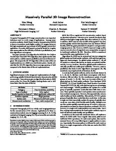
Theses fractured incident lights form various shapes on the detector’s plane and we call them “patterns”. I show them in Figure 5. Shape of pattern is determined by the 3D location and the pattern represents 3D locations of point source. Total area of a pattern is as large as a single micro lens and constant independently of its shape. A small point light source in 3D space is transformed to pattern of constant area on 2D plane. This is not “point to point” transformation but “point to area” transformation. This means that this transformation is complex one and depth information is conserved.
Figure 5. 3 patterns on the detector which represent depth of point source are shown. Left pattern represents point source at depth of f (f: focal length of micro lens). The center one is 2f and the right one is 7f. Red points are centers of micro lenses or “ cells”.
Light-field data is congregation of these patterns all over the detector’s plane. This transformation is kind of encoding process of 3D to 2D using a lens array plate. Refocusing is a process to generate 2D image, picking up pixels from lightfield data according to a pattern which corresponds to your selected focal point and summing them up for an individual pixel of the generated image. I show actual light-field data acquired with our light-field camera in Figure 6. Differently from hologram, light-field data conserve an outline of image in lower special frequency and it contains depth information in higher special frequency. As I have explained, it consists of small cells which are conjugated with an aperture of an imaging lens and whose contents represent directions of rays.
cell
Figure6. Actual light-field data. Depth-information is superimposed in higher space frequency of image and upper left image looks like a normal picture. Enlarging the Image and some structures emerge. The image consists of many small circles we call “cell”.
2.2
Reconstructing 3D scene
Reversed transformation of light-field camera is no other than reconstructing process of light-field display. A light field camera encodes 3D image into 2D light-field data and a light-filed displays decodes light-field data back to 3D image using lens array. Only necessary process to do before decoding is to invert light-field image for each single micro lens, because perspective is inverted near for far in reconstructed image. Our light-field display consists of a 20-inches-flat LCD and a lens array panel attached directly above the LCD’s surface. Lenses are aligned as micro lenses of the light-field camera are aligned and correspond each other. 3D image is reconstructed or decoded from 2D light-field data by corresponded the display’s lens array plate to the MLA of lightfield camera. Decoded and emerged 3D image is optically compressed one and it appears near the surface of the lens array plate. Angle of the cone which is composed from a base, cross section of lens array’s surface and an apex, point source is determined by F-number of a micro lens (or NA of a micro lens). The number of micro lenses the cross section contains must be less than pixels single micro lens contains, because total number of pixels with which a single point source in space is formed is equal to number of pixels a single micro lens contains. So, the cross section cannot be larger than the area theses pixels’ number of micro lenses occupy. In this way range of reconstructed image is determined. In our 20-inches light-field display, total depth of reconstructed image is generally less than 300mm. When diameter of an individual lens correspond to N pixels of the flat display and its focal length is f, the range of depth within which an image is reconstructed is equal to plus/minus Nf. Supposing the diameter N is 14 pixels and focal length f is 10mm, reconstructed range should be equal to plus/minus 140mm actually. Depth of reconstructed image can be said to be optically reduced to 280mm(140mm*2). This image can be easily transformed to full-depth image using a convex lens and forming virtual image from this compressed image. Nevertheless, I do not think it necessary to reconstruct a full-depth image, because both they are optically equal for a speculator-same image on the retina. Furthermore, coincidence of surface of the display and 3D image plane can relieve visual contradiction and this 3D display can be free from 3D sickness.
Figure 7. Our 20-inches light-field display. Optically compressed 3D image is reconstructed near lens array’s surface.
alignments Honeycomb arrangement(rationalized) Diameter of lens 1.74(mm)/14 (pixels) Focal length of lens 9.76(mm) F-number 5.6 Pixel size 0.1245(mm) Pixel number 3840 * 2400(pixels) Size of display 478 * 299 (mm) Table 1: specifications of our 20-inches light-field display
2.3 Resolution of reconstructed image (1) Defocusing of micro lens Though in refocusing or 2D image reconstruction from light-field data its resolution can be finer than density of MLA and up to density of detector’s pixels in theory, it is a little bit different as for a light-field display -integral type 3D display. In refocusing operation (generating 2D image at desired focal plane from light-field data), a single pixel of generated 2D image is an integration of pixels which belong to area of a single micro lens, because a single pixel of generated 2D image is an integration of all directions of rays which goes through a point corresponded to this pixel at desired focal plane in space. In our light field camera, summing up almost 170 pixels of light field data for a point is necessary to generate a single pixel of 2D image. Resolution of this generated 2D image would be same as density of MLA, if we think that a single generated pixel occupies an area as large as micro lens and each of them is independent and is not interfered. However, areas of summing up can be regarded as superimposed and higher resolution can be attained by proper numeric operation. An area can be thought as of a convolution and that a point (a pixel of a generated image) is enlarged or defocused by a point spread function (PSF) with which a light field camera essentially provides. Conditions are different in 3D reconstruction. A pixel of light-field data correspond to a ray of assigned direction and position. Then a single set of pixels belong to a single micro lens assigns rays which go from a position and all directions. There are no convolutional elements and it seems difficult to recover higher resolution. To get higher resolutions than density of micro lenses, micro lenses should be set defocused on display plane. This notion seems similar to Georgiev’s proposal to get super resolution. However, think reverse, incident light for outgoing light, then, in the condition of lens’s setting defocused, light incident to a micro lens is blurred and the blurred point on display’s surface are shifted according to incident position of the light to the lens. So, then image can be described in convolutional equation and this being blur is solvable. When blur function is f , ratio of defocus is d and function of the light is g, then light field data I(x) can be described as follows. 𝐼(𝑥) = ∫ 𝑑 ∙ 𝑓(𝜏)𝑔(𝑥 ∙ 𝑑 − 𝜏)𝑑𝜏
(4)
This procedure means that conjugate relation in our light field system is a little bit changed. This intended defocused condition can be said that the system is shifted from plenoptics 1.0 condition to medium position between plenoptics 2.0 condition and plenoptics 1.0, although the style of light-field data is different from plenoptic2.0. In plenoptics 2.0, recording style of the camera is not complex transition but multi-camera system as I mentioned. Analyzing parallax of small images by each micro lens is an only measure to realize 3D scene from acquired data because data itself does not include depth data. For 3D display, 2D image, not 3D image is reconstructed in space, using this plenoptics 2.0. Its quality of reconstructed image is better than that of plenoptics1.0 system.(This advantageous compact optical system to reconstruct 2D image in space is applied for head mount display.) Closing to Plenoptc 2.0 and shifting from original light-field(plenoptics1.0), a light field display loses uniformity of image reconstruction all over the depth and accuracy of directions of rays instead of image resolution.
Reconstructed point in space Reconstructed point in space
Figure 8.: Left figure shows condition original light field display. Cross section of rays represents reconstructed volume in space. Right figure shows defocused light filed display and at some depth it reconstructs sharp 3D image.
(2) Side effect by defocusing Though resolution of image is improved by this defocusing of micro lenses, resolution of light’s direction becomes worse and cross-talk of rays occurs. Resolution of image and direction are of trade-off relation. With degradation of direction’s resolution to some extent, quality of 3D image a speculator look at can be improved. What is matter with the degradation of light direction? If the size of projected pixel defocused on the face of speculator is smaller than pupil distance of a speculator, there is no problem about this cross talk but the cross talk can be useful.(Figure 9.) This cross talk between projected pixels (and smaller than pupil distance) causes interpolating between pixels and a generated image is connected to next one continuously and smoothly when eyes move. It looks like “Depth-Fused 3D Display”; Interpolating effect occurs in human visual sensation. (Figure 9,10) For example, when pixel size of flat display is 0.1245mm, diameter of micro lens is 1.743mm or equal to 14 pixels, focal distance of micro lens is 9.76mm(F/5.6) and distance to a speculator is 1000mm, then a single pixel is projected as 12.8mm rectangle and the area a single micro lens covers is projected as 179mm diameter of circle on the face. In case of lens array’s being defocused, defocused images of pixels are projected to a speculator’s face and they are superpositioned. In Figure 8 I show the condition of these projections both focused and defocused. in Figure 10.
Figure 9. Flat displays’ pixels are projected to a speculator. Left figure shows a projection of focused condition. And right one shows a projection of defocused condition.
Light intensity
Projected blurred pixel
Position of projected pixel Figure 10. Projected pixel’s images on the face are defocused and enlarged by a blur function. They are superimposed and cause interpolation effect by which a speculator feels continuous transition of views
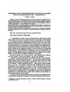
Then, our 3D light field display has higher resolution than density of micro lenses. Figure 11 are pair of pictures which are taken actual 3D displays. Left one is of resolution as fine as density of micro lenses and right one is a picture of our display which attains some super resolution. You can find that higher resolution of 3D display than micro lens density is realized.
Figure 11. :Pictures of actual light-field display. Left figure shows a display of resolution as fine as density of micro lens and a display of right picture has higher resolution.
Nowadays even common cellular phone has a display unit of high resolution (full HD resolution:1920X 1080)and we can expect 4K displays in foreseeable future. We adopted a common cellular phone (NEXUS 5) for our light-field display and made a lens array plate for this cellular phone. Then portable light-field display is completed.(Figure 12)
(3) Artificial 3D light field image Encoding processes of transforming 3D scene to 2D light-field data have been mentioned so far and are understood well. Then, simulating them with a computer, we can realize “Computer Generated” images or animations on a light-field display; Generate 3D scene in a computer and compress it “optically” to match the light field display, then encode each pixel into 2D light field data according to a pattern its depth determines. When you display this light field data on the cellular phone and look over it through the lens array plate, you can find 3D scene on the screen of the cellular phone.
Figure12. Light-field display using common cellular phone NEXUS5. A 3D picture acquired by a light field camera is displayed on the cellular phone(right). Computer Generated 3D animation is displayed (left). Table 2: specifications of the light-field display using a cellular phone Alignments Honeycomb arrangement(rationalized) Diameter of lens 0.77(mm)/14 (pixels) Focal length of lens 2.16(mm) F-number 2.8 Pixel size 0.055(mm) Pixel number 1920 * 1080(pixels) Size of display 106 * 59 (mm)
(4) View angle and adjustment of lens array to display Notable features of our light-field display are wide view angle and adjustment free of a lens array to the display. When the center of light-field data’s “cell” is not on the optical axis of a micro lens, this off-axis condition can be regarded as tilting of optical axis in the light-field display. Therefore, 3D reconstruction or light-field decoding process occurs along with tilted optical axis. 3D image is reconstructed regardless of optical axis tilting without damages and reconstructed image is shifted parallel to lens array surface. Basically view angle determined by F-number of micro lens. When F-number of micro lens is 2.8, view angle is about 20 degree. In the light field display, next “cell” is also available for a micro lens. Then, when you look from out of the primary view area, you can see 3D image reconstructed from next “cells”. It goes without saying that two next and three next “cell” are available as long as micro lens functions optically.
Adjustment of the lens array is no more than adjusting borders of regions which micro lenses cover. So, in case that right and left eyes straddle this border, reverse vision occurs. When a “cell” is projected on face as large as 400mm and pupil distance is 60mm (most convenient condition), the probability of reverse vision can be estimated as 0.125. View angle a single lens covers
Tilted optical axis
“cell”
Figure 13. Schematic diagram of explaining off-Axis condition. Off-axis of lens array can be regarded as tilting of axis.
3. CONCLUSIONS A light-field display generates volume 3D image nearby lens array plate. It is a kind of integral displays which have been proposed so far, not a stereoscopic display which shows plural 2D images on a screen. Light-field data which is displayed on a flat display, a main component of a light-field display, is based on light-field theorem or is acquired by a light-field camera. I conclude its features as follows. (1) Light-field camera and display are devices which encode 3D scene to 2D light-field data and decode back to 3D scene by a light-field display. (2) Light-filed display reconstruct optically compressed 3D image whose depth is about ten times as thick as focal length of lens array in both far and near directions. (3) Reconstructed image by light-field display can be of resolution finer than density of micro lenses. (4) View angle of light-field display is several times as big as angle of micro lens’ numeric aperture(N.A.). (5) It is not necessary to adjust lens array plate to flat display precisely.
REFERENCES [1] B.Javidi, F.Okano,[Three-dimensional TV, Video and Display]Springer-Verlag,Berlin Heidelberg,101-141 (2002). [2] R. Ng, M. Levoy, M. Bredif, G. Duval, M. Horowitz, and P. Hanrahan. "Light Field Photography with a HandHeld Plenoptic Camera." Stanford University Computer Science Tech Report CSTR 2005-02, April (2005). [3] A.Lumsdaine, T.Georgiev,"The Focused Plenoptic Camera" ICCP,(2009) [4] A.Lumsdaine,T.Georgiev,G.Chunev,"Spatial Analysis of Discrete Plenoptic Sampling"SPIE Electronic Imaging,(2012).: [5] S.Yamada, S.Suyama, "Influence of Discontinuous Image Flipping and Crosstalk on Perceive Depth by Monocular Motion Parallax."Ite technical report vol. 40 ,(2016). [6] R.Ng,"Fourier Slice Photography"ACM SIGGRAPH,(2005)
[7]
J.Arai, F.Okano, H.Hoshino, and I.Yuyama ,"Gradient-index lens-array method based onreal-time integral photography for three-dimensional images "APPLIED OPTICS Vol. 37, No. 11(1998) [8] T.Iwane, M.Nakajima"3D Display using computer-generated light field data"Proc.IDW,(2014) [9] D.Lanman, D.Luebke,"Near-Eye Light Field Displays" in ACM SIGGRAPH 2013 Emerging Technologies, July (2013) [10] S.Suyama, H.Takada, K.Uehira, and S.Sakai, "A Novel DirectVision 3-D Display Using LuminanceModulated Two 2-D Images Displayed at Different Depths," SID’00 Digest of Technical Papers,(2000)