Light propagation and reflection-refraction event in absorbing media
Recommend Documents
solution. OA experiments were also conducted and data were in good agreement with those .... pared to an ultrasonic wavefront because it suffers less dis-.
broadened absorbing line shape are considered, with their imaginary and real part of the ... 4. Y. Y. Li, W. Pang, Y. Z. Chen, Z. Q. Yu, J. Y. Zhou, and H. R. Zhang, ...
Jan 22, 2014 - Its frequency bandwidth increases with absorption, and the exact ... b. I. INTRODUCTION. In mesoscopic transport, wave interference ... a necklace state that is formed via coupling of several ... the output end determines the total tra
on a sphere, and how this sampling scheme is used in the context of our path tracer to accelerate photon tracing within participating media. 4.2. Precomputation.
Accelerated Light Propagation Through Participating Media. Richard Lee and Carol O'Sullivan. Graphics, Vision and Visualisation Group, Trinity College Dublin, ...
2Israel Oceanographic and Limnological Research, Yigal Allon Kinneret Limnological Laboratory, P.O. Box 447,. Migdal 14950, Israel. Received 15 April 2005; ...
Toronto, Ontario M5G 2M9. Canada. Abstract. A Monte Carlo model for polarized light propagation in birefringent, optically active, multiply scattering media is ...
Jun 22, 2012 - These responses are functionals of the electric field. They ... electric field through the linear propagator eikz (kx,ky ,Ï)z: Eâ¥. + (kâ¥, Ï, z) = â.
Aug 10, 2010 - that the filtering can be carried out at a field camp or in a hotel room, without the .... Snow was collected by volunteers near Eureka in Northern ...
Aug 10, 2010 - sheet and on the Arctic Ocean, of melting glacier snow and sea ice as well as cold ..... steel spatula to put snow into a plastic bag (or alternatively, pushed a glass jar into the ... collected at vertical intervals of 5 cm throughout
Jul 4, 2006 - For TM modes we outline the importance of skin-effect, which causes the full reflection of the incoming light. We then illustrate the possibility.
In case 4(r) = 0 for r < &, and some roe R we say that u is a finite travelling wave. A FTW with positive (resp. negative) velocity c is called in thermal propagation a.
immediately beyond the probe is P2 = P1 â Psca, where P1 is the optical power carried by ... P2/P1 = 1 â Psca/P1 and the overall intensity transmission change ...
Aug 21, 2010 - in aerosol and precipitation at the Maldives Climate Observatory Hanimaadhoo during the period May 2005 to February 2007 have made it ...
Feb 1, 2008 - arXiv:cond-mat/9905168v1 [cond-mat.stat-mech] 12 May 1999. Propagation and organization in lattice random media. Patrick Grosfils â and ...
Sep 27, 2006 - which in general differs from the probe field frequency. We thus conclude that in ...... [5] L. V. Hau, S. E. Harris, Z. Dutton and C. H. Behroozi,.
In this paper an overview on semiconductor refractive index theory and negative ..... spoon changed to the cup by means of complimentary media (Bottom).
of the open-source k-Wave Acoustics Toolbox [5], [6]. This model can account for the propagation of nonlinear ultrasound waves in generally heterogeneous ...
Apr 1, 2009 - models (Heald et al., 2005; Henze and Seinfeld, 2006; Kroll. Correspondence to: V. F. McNeill. ([email protected]) et al., 2006).
Nov 5, 2014 - We have analyzed the spectral and kinetic characteristics of phosphorescence at room temperature on a millisecond time scale for transparent ...
two semiconductor device types at the heart of optical high speed data
communications, namely the PIN ..... CHAPTER 2 PIN PHOTODIODE BASICS .
Oct 8, 2014 - of 4800 m and then at regular altitude intervals to the mountain top. ... Because mountain climbing is a physically demanding and potentially ...
duodenal enterotomy with mucosal-to-mucosal opposition. Preparation of CS-GGS nanoparticles. GGS nanoparticles with controllable near infrared absorp-.
cancer, and includes surgery, radiotherapy, chemotherapy, and endoscopic therapy. However, limitations of all .... that looks smooth and white, with blood vessels that are ... After exposure, the esophageal tissues were harvested to investigate ...
Light propagation and reflection-refraction event in absorbing media
The light propagation within an absorbing medium and the reflection and refraction at the interface of two absorbing media are studied. By using the unit vectors ...
January 10, 2010 / Vol. 8, No. 1 / CHINESE OPTICS LETTERS
The light propagation within an absorbing medium and the reflection and refraction at the interface of two absorbing media are studied. By using the unit vectors denoting the planes of constant field amplitude and constant phase respectively, the light propagation and attenuation are described by the effective refractive indices which depend on both the complex refractive index of the medium and the angle between the unit vectors. With the expression for the light propagation, the corresponding Snell’s law and the expression of Fresnel coefficients are obtained, which can be applied to describe the reflection-refraction event at the interface between an arbitrary combination of transparent and absorbing media. OCIS codes: 260.2110, 120.5700, 120.5710, 080.1510. doi: 10.3788/COL20100801.0111.
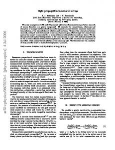
Geometrical optics approximation (GOA) of light scattering by large particles with the size much larger than the wavelength of the incident light is considered as a good method by avoiding difficulties in Lorenz-Mie calculation. Studies on the GOA of light scattering have been of interest to many researchers during the past several decades[1−12] . Most of the publications treat the light scattering by transparent particles. As far as we know, the GOA calculations of light scattering by absorbing particles are rare due to the difficulties in calculating the propagation of light in the absorbing medium and its Fresnel coefficients at the interface of the media. This problem was recently investigated by Yang et al.[13,14] by introducing the effective refractive index, and they presented the formulae for calculating the Fresnel coefficients at the interface of the transparentabsorbing media, which was based on the assumption of the plane of constant amplitude being parallel to the interface. The assumption of Yang et al. is reasonable for the reflection-refraction event while the incident light hits the absorbing particle suspended in air, as p = 0 in Fig. 1. However, for the high order reflection-refraction events (i.e., p = 1,2,· · · ) in which the light within the particle is reflected and refracted at the interface, the plane of constant amplitude is usually unparallel to the interface. Besides, if one would calculate the coated particles containing absorbing core and shell, he has to account for the interface between absorbing-absorbing media. In this letter, we study the light propagation in an absorbing medium and the reflection-refraction event of the light at the interface of absorbing-absorbing media. The media are assumed to be uniform and isotropic. The parameters such as the permeability ε, the permittivity µ, and the conductivity σ are time-independent. The time dependence of the light wave is expressed in the form exp (iωt), where ω is the angular frequency and t is the time. Substituting the time-harmonic wave (i.e., E (r, t) = E (r) exp (iωt) and H (r, t) = H (r) exp (iωt)) into the
1671-7694/2010/010111-04
Maxwell equations (in SI units)[15,16] , we may obtain ½ ∇ × E (r) = −iωµH (r) , (1) ∇ × H (r) = iω εˆE (r) ½
ˆ 2 E (r) = 0 ∇2 E (r) + k02 m , 2 2 2 ˆ H (r) = 0 ∇ H (r) + k0 m
(2)
where εˆ = ε − i ωσ is the equivalent complex permeability, k0 is the wave number in vacuum. The complex refrac2 tive index m ˆ is defined by m ˆ 2 = (ω/k0 ) εˆµ = c2 εˆµ (c is the light speed in vacuum), whose real and imaginary parts mre and mim are obtained as m ˆ = mrev− i · mim , ! u Ãr u1 µ2 σ 2 t 2 2 µ ε + + µε mre = c 2 ω2 . (3) v Ãr ! u 2 2 u1 µ σ m = ct µ2 ε2 + − µε im 2 ω2
Fig. 1. Schematic illustration of the reflection-refraction events of the light in an absorbing sphere.
c 2010 Chinese Optics Letters °
112
CHINESE OPTICS LETTERS / Vol. 8, No. 1 / January 10, 2010
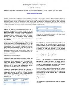
amplitude are unparallel to the planes of constant phase. The unit vector q is normal to the planes of constant amplitude and the unit vector s is normal to the planes of constant phase. The angle between these two vectors is ξ = cos−1 (q · s). Let the electromagnetic field be ½ Fig. 2. Schematic illustration of the wave propagation in an absorbing medium.
Figure 2 schematically illustrates the light propagation in an absorbing medium, wherein the planes of constant
E (r) = E0 · exp [−i (ks s − ikq q) · r] , H (r) = H0 · exp [−i (ks s − ikq q) · r]
where (E0 , H0 ) is the electromagnetic field at the origin of the system, ks and kq are the parameters to be determined. Combining Eqs. (2) and (4), we find
v s u µ ¶2 u 1 2m m k u 2 re im s 2 − m2 ) + 2 − m2 ) = (m + (m N = t s re re im im k0 2 cos ξ v s . u µ ¶2 u kq 2mre mim u1 2 − m2 )2 + 2 − m2 ) N = = (m − (m t re re im im q k0 2 cos ξ
The parameters Ns and Nq are the so-called effective refractive indices and are relative to the propagation and attenuation of light in the medium. Their values depend not only on the complex refractive index but also on the angle between the planes of constant amplitude and of constant phase. By substituting Eq. (4) into Eq. (1), we have 1 H (r) = k0 (Ns s − iNq q) × E (r) ωµ . (6) E (r) = − 1 k0 (Ns s − iNq q) × H (r) ω εˆ This means that, if Nq 6= 0 and ξ 6= 0, the conditions for transversality are broken and the waves are inhomogeneous. Reflection-refraction event of the light wave is illustrated in Fig. 3, wherein the absorbing media are characterized with (εi , µi , σi ) and (εt , µt , σt ) in which the subscripts i and t represent the incident and refracted sides, respectively. The interface is aligned in the xy plane. The incident, reflected, and refracted light can thus be expressed as ½ Ej (r) = E0j · exp [−ik0 (Nsj sj − iNqj qj ) · r] , (7) Hj (r) = H0j · exp [−ik0 (Nsj sj − iNqj qj ) · r] where the subscript j can be replaced by i, r, and t, denoting the incident, reflected, and refracted light, re-
(4)
(5)
spectively. The boundary conditions, i.e., the spatial (and temporal) variation of all fields must be the same at the interface, mean that the phase factors all equal at z = 0. This results are shown in the following expressions: ½
Nsi si · r|z=0 = Nsr sr · r|z=0 = Nst st · r|z=0 . Nqi qi · r|z=0 = Nri qr · r|z=0 = Nqt qt · r|z=0
(8)
It may be immediately found that all these three wave vectors (i.e., si , sr , and st ) must lie in a plane and so do the vectors qi , qr , and qt . For simplicity, our study is limited on the special case that all the abovementioned unit vectors are coplanar. Therefore, from Eq. (8) we may find that (
Nsi sin θi = Nst sin θt , Nqi sin ζi = Nqt sin ζt .
(9) (10)
Equation (9) denotes that the angle of incidence equals the angle of reflection (i.e., θi = π − θr ) and the same relationship holds between the angles ζi and ζr . A combination of Eq. (10) with Eq. (5) for the refracted light leads to
v s u ¡ 2 ¢2 2 2 2 2 2 u m − m + N sin ζ − N sin θ i i t,re u qi si t,im 1 2 Nst = u t 2 ¡ +4 (mt,re mt,im − Nsi Nqi sin θi sin ζi ) ¢ 2 2 2 2 2 2 + m − mt,im + Nqi sin ζi + Nsi sin θi v s t,re u ¡ 2 ¢2 2 2 u mt,re − m2t,im + Nqi sin2 ζi − Nsi sin2 θi u1 2 Nqt = u t 2 ¡ +4 (mt,re mt,im − Nsi Nqi sin θi sin ζi ) ¢ 2 2 2 2 2 2 + mt,im − mt,re + Nqi sin ζi + Nsi sin θi
.
(11)
January 10, 2010 / Vol. 8, No. 1 / CHINESE OPTICS LETTERS
Equation (11) means that the effective refractive indices Nst and Nqt to determine the refracted light depend on the refractive index of the refracted medium (mt,re and mt,im ) and the parameters of incident wave (θi , ζi , Nsi , and Nqi ). Once the effective refractive indices Nst and Nqt are determined, Snell’s law, as given in Eq. (10) can be solved, wherein the equation Nsi sin θi = Nst sin θt expresses the direction of the refracted wave and Nqi sin ζi = Nqt sin ζt denotes the planes of constant amplitude of the refracted wave.
Finally, we study the Fresnel coefficients of the electromagnetic wave at the interface of two absorbing media. Due to its inhomogeneity characteristics within the absorbing medium, the electromagnetic wave is decomposed into a transverse electric (TE) mode and a transverse magnetic (TM) mode. In the TE mode the electric vector is perpendicular to the direction of wave propagation whereas in the TM mode the magnetic vector is perpendicular to the direction of wave propagation. For the TE mode, the fields are given as
Ej (r) = E0j,x ex · exp [−ik0 (Nsj sj − iNqj qj ) · r] Hj (r) = [(Nsj sj,z − iNqj qj,z ) ey − (Nsj sj,y − iNqj qj,y ) ez ] ·
where sj,y and sj,z are the components of the unit vector sj on y and z axes, qj,y and qj,z are those of the unit vector qj . However, the direct use of Eq. (12) may lead to an unconservation of energy. This is because that, for the specular reflection, the phase propagation and the absorption are mirror-symmetric about the interface.
Considering that the incident and refracted fields propagate along the positive z direction whereas the reflected field propagates along the negative z direction and the media are absorptive, the refracted field for the TE mode is expressed in a different form:
Er (r) = E0r,x ex · exp [−ik0 (Nsr sr − iNqr qr ) · r] Hr (r) = [(Nsr sr,z + iNqr qr,z ) ey − (Nsr sr,y + iNqr qr,y ) ez ] ·
The boundary conditions for the TE mode require that ½ E0i,x + E0r,x = E0t,x , (14) H0i,y + H0r,y = H0t,y
113
1 . E0r,x · exp [−ik0 (Nsr sr − iNqr qr ) · r] cµr
(13)
which leads to the Fresnel coefficients of reflection and refraction for the TE-mode electric fields:
E0r,x µt (Nsi cos θi − iNqi cos ζi ) − µi (Nst cos θt − iNqt cos ζt ) = rE,TE = E0i,x µt (Nsi cos θi + iNqi cos ζi ) + µi (Nst cos θt − iNqt cos ζt ) . 2µt Nsi cos θi E 0t,x tE,TE = = E0i,x µt (Nsi cos θi + iNqi cos ζi ) + µi (Nst cos θt − iNqt cos ζt )
(15)
Similarly, for the TM mode we have Hj (r) = H0j,x ex · exp [−ik0 (Nsj sj − iNqj qj ) · r] Ej (r) = [(Nsj sj,y − iNqj qj,y ) ez − (Nsj sj,z − iNqj qj,z ) ey ] ·
1 H0r,x · exp [−ik0 (Nsr sr − iNqr qr ) · r] cˆ εr
(17)
for the incident and refracted fields and Hr (r) = H0r,x ex · exp [−ik0 (Nsr sr − iNqr qr ) · r] Er (r) = [(Nsr sr,y + iNqr qr,y ) ez − (Nsr sr,z + iNqr qr,z ) ey ] · for the reflected one. The corresponding boundary conditions for the TM mode are ½ H0i,x + H0r,x = H0t,x . (18) E0i,y + E0r,y = E0t,y
The Fresnel coefficients of reflection and refraction for the TM mode magnetic fields are obtained as
εˆt (Nsi cos θi − iNqi cos ζi ) − εˆi (Nst cos θt − iNqt cos ζt ) H0r,x = rH,TM = H0i,x εˆt (Nsi cos θi + iNqi cos ζi ) + εˆi (Nst cos θt − iNqt cos ζt ) . H 2ˆ εt Nsi cos θi 0t,x = tH,TM = H0i,x εˆt (Nsi cos θi + iNqi cos ζi ) + εˆi (Nst cos θt − iNqt cos ζt )
(19)
114
CHINESE OPTICS LETTERS / Vol. 8, No. 1 / January 10, 2010
Fig. 3. Geometric configuration for the reflection and refraction of the electromagnetic wave at the interface of the absorbing media.
The Fresnel coefficients expressed in Eqs. (15) and (19) depend on the permeabilities, permittivities, and conductivities of the absorbing media, the incident (or reflected) and refracted angles. In addition, they are related to the planes of constant amplitude of the incident (or reflected) and refracted waves. The Fresnel formula satisfies the conservation law naturally. It can be proved that, when the medium is transparent (σ = √ 0), the refractive index given in Eq. (3) is real (mre = c µε and mim = 0) and hence the effective refractive indices in Eq. (5) are Ns = mre and Nq = 0. As a result, Eq. (6) is simplified to 1 H (r) = k0 mre s × E (r) ωµ . 1 E (r) = − k0 mre s × H (r) ωε
(20)
Therefore, the electromagnetic field in the unbound transparent medium meets the conditions for transversality and is homogeneous. For the reflection-refraction event of the electromagnetic wave at the interface of transparent-absorbing media, we may simply assume one of the conductivities to be zero, i.e., σi = 0 or σt = 0. This is very useful while one calculates light scattering by an absorbing particle within the geometric optics regime. As shown in Fig. 1, σi = 0 corresponds to the case of the incident light hitting the particle (p = 0) whereas σt = 0 corresponds to the high order reflection-refraction events when the ray transmission is from the absorbing particle into air (p = 1,2,· · · ). The most special case is the reflection and refraction at the interface of transparent media, in which both the conductivities are zero and expressions of the Fresnel coefficients are simplified into the form given in Ref. [16]. In conclusion, the wave propagation in an absorbing
medium and the reflection-refraction event at the interface between absorbing media are studied. The wave propagation in the absorbing medium is characterized by the so-called effective refractive indices Ns and Nq together with their corresponding unit vectors q and s. The light propagates along the unit vector q and the field amplitude attenuates along the unit vector s. The effective refractive indices depend on both the complex refractive index of the medium and the angle between q and s. By using these parameters, Snell’s law is expressed in a real form which determines not only the directions for the propagation of the reflected and refracted waves but also the directions for the decay of these waves. The Fresnel coefficients at the interface of the absorbing media are obtained. Snell’s law and the Fresnel coefficients obtained in this work can be applied to the reflectionrefraction event at the interface of the media, wherein either/both of them is/are absorbing or transparent. The results may find applications in GOA of light scattering and other ray-tracking calculations. This work was supported by the National Natural Science Foundation of China (No. 50876069), the Ministry of Education of the People’s Republic of China (No. 208041), and the Shanghai Municipal Education Commission (No. 07ZZ88). References 1. G. E. Davis, J. Opt. Soc. Am. 45, 572 (1955). 2. H. C. Van de Hulst, Light Scattering by Small Particles (Wiley, New York, 1957). 3. W. J. Glantschnig and S.-H. Chen, Appl. Opt. 20, 2499 (1981). 4. A. Ungut, G. Grehan, and G. Gouesbet, Appl. Opt. 20, 2911 (1981). 5. E. A. Hovenac, Appl. Opt. 30, 4739 (1991). 6. F. Xu, X. Cai, and K. Ren, Appl. Opt. 43, 1870 (2004). 7. A. L. Aden and M. Kerker, J. Appl. Phys. 22, 1242 (1951). 8. X. Li, X. Han, R. Li, and H. Jiang, Appl. Opt. 46, 5241 (2007). 9. H. Yu, J. Shen, and Y. Wei, Particuology 6, 340 (2008). 10. F. Xu, K. F. Ren, and X. Cai, Appl. Opt. 45, 4990 (2006). 11. F. Xu, X. Cai, and J. Shen, Acta Opt. Sin. (in Chinese) 23, 1464 (2003). 12. W. Li, K. Yang, X. Zhang, M. Xia, X. Lei, and Q. Liu, Acta Opt. Sin. (in Chinese) 26, 647 (2006). 13. P. Yang and K. N. Liou, J. Opt. Soc. Am. A 12, 162 (1995). 14. P. Yang and K. N. Liou, J. Quantum Spec. Rad. Trans. 110, 300 (2009). 15. J. A. Stratton, Electromagnetic Theory (McGraw-Hill, NewYork, 1941). 16. M. Born and E. Wolf, Principles of Optics (7th Expanded edn.) (Cambridge University Press, Cambridge, 1999).